1
Larson Systems Inc.
Capacitance Free Length Gage
User Manual
INTRODUCTION................................................................................................................................................ 3
SPRING MEASUREMENT BASICS ............................................................................................................... 3
CALIBRATION..................................................................................................................................................... 3
A TYPICAL CALIBRATION CYCLE:...................................................................................................................... 4
A TYPICAL MEASUREMENT CYCLE .................................................................................................................... 4
IMPORTANT CONSIDERATIONS .......................................................................................................................... 5
Sensitivity...................................................................................................................................................... 5
Multiple Sampling ........................................................................................................................................ 5
Thermal Stability .......................................................................................................................................... 5
Zeroing the Output Voltage (Offset)............................................................................................................ 5
Zeroing Errors.............................................................................................................................................. 6
Probe Contact Errors................................................................................................................................... 6
HARDWARE........................................................................................................................................................ 7
PROBE DRIVER ................................................................................................................................................... 7
CONNECTIONS .................................................................................................................................................... 8
SOFTWARE ......................................................................................................................................................... 9
LP_INITIALIZE .................................................................................................................................................... 9
LP_SETUP_PROBE ............................................................................................................................................... 9
LP_ZERO_PROBE .............................................................................................................................................. 11
LP_GET_SPRING_LENGTH ................................................................................................................................ 12
LP_GET_PROBE_VOLTAGE ............................................................................................................................... 12
LP_VOLTS_OUT ................................................................................................................................................ 13
LP_CONVERT_VOLTS_TO_LENGTH ................................................................................................................. 13
LP_FIT_POINTS ................................................................................................................................................. 14
LP_FIND_HORIZONTAL_POINT......................................................................................................................... 15
2
Introduction
The Larson Systems Capacitance Free Length Gage is a self contained probe driver
assembly and probe for adding capacitance based spring free-length measurement to
OEM coilers and gages. A disk with sample C code is included to assist in the
implementation of the instrument. An optional National Instruments data acquisition card
can also be included
The system is designed for use in CNC coilers and grinders, enabling the CNC designer
to incorporate internal gaging without the necessity of designing gaging hardware or
interfaces to external gages.
This manual contains information on the basic concepts of spring measurement, the
included hardware and the included software.
Spring Measurement Basics
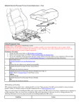
Non-contact spring measurement is accomplished with a probe
containing a non-contact sensor and an integral micrometer. The
probe is mounted to the coiler face and positioned so the spring
approaches the probe tip as it is formed (figure 1).
The probe uses an electric field to measure the gap between the
probe tip and end of the spring. Changes in this gap create
changes in output voltage, which correspond to changes in spring
length.
Figure 1
Calibration
To determine the corresponding spring length from the output voltage, the system must
be calibrated with each use. During calibration, the user winds a spring but does not cut it
off. The user then uses the system interface to teach it three measurement points. These
three points are used in the calculation of spring length during production. The probe's
micrometer is used to simulate changes in spring length by changing the probe’s distance
from the spring. During calibration the variables used in the length calculation are set.
These variables are:
Variable
Example
Nominal length (desired length)
45mm
Tolerance
±1mm
Output voltage for nominal spring
0.065VDC (45mm spring)
Output voltage for nominal plus tolerance
4.56VDC (46mm spring)
Output voltage for nominal minus tolerance
-3.84VDC (44mm spring)
3
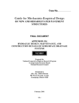
The relationship between the output voltage and the spring
length is nonlinear. If actual length measurements are to be
reported to the user, then the spring length calculation will
have to include a linearization algorithm. The included
software provides a function for doing this using a second
order, three-point curve fitting algorithm (parabolic). If the
voltage is only used to sort springs which exceed the tolerance,
then linearization is not necessary.
Figure 2
Spring lengths are reported as deviation from nominal. For
actual spring length, the nominal length will have to be added.
Using our example values from above, the length function may return a length deviation
of +0.02mm. The actual spring length would be 45.02mm.
A typical calibration cycle:
1. Operator enters the nominal spring length
2. Operator enters the tolerance
3. Operator winds a spring but does not cut off
4. Operator sets the probe gap (see Important Considerations below)
5. Operator activates a “Teach” or “Set Nominal” button
6. System adjusts output voltage to near zero (or the operator is instructed to zero the
output with the potentiometer)
7. System captures and stores the remaining offset voltage. This voltage represents a
nominal spring
8. Operator uses the micrometer to adjust the probe position to simulate a spring at
the “long” tolerance point.
9. System captures and stores the probe voltage for “long” tolerance
10. Operator uses the micrometer to adjust the probe position to simulate a spring at
the “short” tolerance point.
11. System captures and stores the probe voltage for “short” tolerance
12. System uses stored spring length specifications and captured voltages to generate
linearization coefficients (lp_fit_points).
13. Operator returns probe to nominal gap and starts production
A typical measurement cycle
1. System coils a spring (no cutoff)
2. System reads probe voltage (an average of at least ten readings)
3. System calculates spring length and activates and sorting devices
4. System cuts off spring
5. System corrects for any length error.
4
Important Considerations
Sensitivity
Probe sensitivity is defined as the rate of change of the output voltage for a given change
in spring length. For example, a change of 5V for a 1mm change in length is more
sensitive than a change of 1V for a 1mm change.
The probe sensitivity is dependent on the size of the gap between the probe tip and the
spring. The smaller the gap, the greater the sensitivity.
When calibrated, the output voltage range should be
at least ±1V and not more than ±8V.
If the probe is too sensitive (more than ±8V output change) then the probe must be
moved further away from the spring and recalibrated.
If the probe is not sensitive enough (less than ±1V output change) then the probe must be
moved closer to the spring and recalibrated.
These means that calibrations with smaller tolerances will have to be closer to the spring
and larger tolerances may be farther away.
Multiple Sampling
To reduce the affect of any electrical noise in the system, probe voltage readings should
be captured with multiple readings then averaged. For example, read and store ten
readings of the probe voltage, sum the readings and divide by ten. The number of
readings to be taken and averaged will depend on the running speed of the system and the
amount of noise present in the signal.
Thermal Stability
The probe features a heating element that keeps the probe electronics at 130°F to prevent
thermal drift. This circuit is controlled by a very low speed integrator. If power is
interrupted to the probe, the probe will require two minutes to stabilize.
Zeroing the Output Voltage (Offset)
To provide a full voltage range during production, the output voltage for a nominal spring
must be near zero. There are two ways to zero the output voltage:
•
use a ten turn potentiometer accessible to the user (provided optionally)
•
or use a zeroing voltage into pin 3 of J1.
When using the potentiometer, the zeroing voltage input (J1-3) is disabled. The
potentiometer provides a stable reference for the driver.
When using the zeroing voltage input, the voltage must be stable and low in noise. The
zeroing voltage is amplified (Gain ≈ 50), therefore any thermal drift or electrical noise
can have a significant affect on the output voltage and the spring length measurement.
5
Zeroing Errors
If the probe is too close to the spring, the driver cannot be zeroed. The output voltage will
remain positive. The probe must be moved farther away from the spring and re-zeroed.
If the probe is too far away from the spring, the driver cannot be zeroed. The output
voltage will remain negative. The probe must be moved closer to the spring and rezeroed.
Probe Contact Errors
Sometimes it is helpful to notify the operator if a spring makes contact with the probe tip.
This may indicate a broken cutoff tool. The Test Voltage from J1-4 indicates this
condition. Under normal operation conditions the voltage on this pin is less than 0.2VDC.
If something contacts the tip, the Test Voltage will rise to over 0.7VDC. Using a routine
to verify that this voltage is below 0.5VDC will monitor and report any probe contact
errors.
6
Hardware
Probe Driver
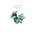
The Capacitance Free Length Driver is a self
contained system for driving the non-contact
probe. The driver electronics produce an output
voltage, which is proportional to the length of
the spring at the probe. Longer springs (closer
to the probe) produce more positive output
voltages.
The output voltage offset must be adjusted to
near zero for a nominal length spring. Probe
Zero adjustments can be made by a DAC output
voltage from the users data acquisition system
or by a ten-turn potentiometer that can be
purchased with the system.
Figure 3
The probe driver is mounted with two screws (M3-0.5). Do not loosen or remove the
probe connector nut. See Figure 3 for panel cutout specifications. The maximum depth of
the threaded mounting holes is 9.5mm (3/8 inch).
7
Connections
J1 Connections
Wire Colors
Pin
Signal
Notes
White
1
Power In
+5 ± 0.5VDC, 0.7A max.
Brown
2
Probe Voltage Out
±10VDC, proportional to spring length, more positive =
longer.
Black
3
Zero Voltage In
(Negative voltage)
0 to -10VDC input voltage used to zero output voltage offset.
<0.5VDC normal operation, >0.5VDC when probe tip is
grounded by contact with spring or other object.
Blue
4
Test Voltage Out
Gray
5
Ground (Common)
0.1V input change yields approximately 5V output change.
8
Software
The floppy disk supplied with the Capacitance Free Length Gage contains several
examples of C language functions that may be useful in the implementation of the driver.
None of these functions are required to use the driver. They are provided as tested
implementation examples. They carry no warranty of functionality within any given
system. They are ANSI C compatible and should be useable in most systems using a C
development environment. All functions start with “lp_” to identify them as Larson
Procedures.
The following procedure list gives detail on the provided functions to ease the
understanding and implementation of them.
lp_initialize
Description
Initializes lp global variables. All variables are normally set to valid
values during normal operation, however, this function is provided to
prevent any unexpected errors after start up.
void lp_initialize( void )
{
short_voltage
=-1.0;
nominal_voltage = 0.0;
long_voltage
= 1.0;
short_length
=-1.0;
nominal_length = 0.0;
long_length
= 1.0;
fit_points(short_voltage, nominal_voltage, long_voltage,
short_length, nominal_length, long_length,
&a_coeff, &b_coeff, &c_coeff
);
find_horizontal_point(a_coeff, b_coeff, &horizontal_point);
}
lp_setup_probe
Description
Goes through the steps necessary to zero the probe and set up a
linearization curve. These steps must be done every time the setup is
changed. Much of this code must be written by the user because it
involves taking input from the operator which can be done many
different ways. This is simply a list of steps in the correct order.
Return value: none
Parameters:
none
void lp_setup_probe()
{
9
/*
instruct user to put a nominal length spring in front of the probe
*/
lp_zero_probe();
/*
obtain nominal spring length from user and store in nominal_length
*/
nominal length =
nominal_voltage = lp_get_probe_voltage();
/*
instruct user to adjust the micrometer probe to simulate a long
(maximum) length spring
*/
/*
obtain long spring length from user and store in long_length
*/
long_length =
long_voltage = lp_get_probe_voltage();
/*
instruct user to adjust the micrometer probe to simulate a short
(minimum) length spring
*/
/*
obtain short spring length from user and store in short_length
*/
short_length =
short_voltage = lp_get_probe_voltage();
if( -1 == lp_fit_points(
short_voltage, nominal_voltage, long_voltage,
short_length, nominal_length, long_length,
&c_coeff, &b_coeff, &a_coeff)
)
{
/* If there is a problem with the numbers input to fit_points,
code within these brackets will be run. */
}
if( lp_find_horizontal_point(a_coeff, b_coeff, &horizontal_point) )
{
/* If there is a problem with finding the horizontal point, code
within these brackets will be run. */
}
}
10
lp_zero_probe
Description
This function will zero the output voltage of the probe driver by adjusting
the zeroing voltage put out by a D to A converter. When using a
potentiometer for zeroing, this function is substituted by instructions and
feedback to the user to adjust the potentiometer.
Return
value:
If there is an error in acquiring the voltage, or the probe cannot be zeroed,
a –1 is returned, otherwise the function will return 0;
Parameters:
none
int lp_zero_probe()
{
/* 'i' is a counter to show how many times the loop has been executed
*/
int i;
/* 'high' is the current upper limit of analog output voltage
The desired voltage should be less than this.
0 volts is the largest zeroing voltage you should put into the SPD-2 */
double high = 0.0;
/* 'low' is the current lower limit of analog output voltage
The desired voltage should be higher than this.
-10 volts is the smallest zeroing voltage you should put into the SPD-2
*/
double low = -10.0;
/* 'in' is the most recent voltage read */
double in = 0.0;
/* 'last_in' is the previous voltage read */
double last_in = 1.0;
/* 'out' is the voltage to be sent out to the probe driver */
double out;
/* Three conditions must be met for the loop to continue:
1. i < 100
If the loop has executed 100 times, there's probably something
wrong.
2. fabs(in-last_in) < 0.01
Once the voltage read back from the probe driver stops changing,
you know that you've zeroed in on the appropriate output voltage.
3. high > low
If high becomes less than low you have reached the zero volts point
or something has gone wrong. */
for( i=0; i<100 && fabs(in-last_in)<0.01 && high>low; i++ )
{
/* Output a voltage halfway between the upper and lower limits. */
out = (high + low)*0.5;
lp_volts_out( out );
11
/* Update last_in and read new voltage. */
last_in = in;
in = lp_get_probe_voltage();
/* Check whether new voltage is positive or
negative and update high or low accordingly. */
if( in > 0 )
low = out;
else
high = out;
}
/* Check for errors */
if( i>=100 || fabs( in ) > 1.0)
return -1;
return 0;
}
lp_get_spring_length
Description
Reads the analog voltage from the probe and converts it to length.
lp_setup_probe must be completed before this function is used.
Return value: Spring length
Parameters:
none
double lp_get_spring_length()
{
return lp_convert_volts_to_length(
}
lp_get_probe_voltage()
);
lp_get_probe_voltage
Description
Acquires the output voltage from the spring probe. Range is ± 10VDC.
Return value: Voltage reading.
Parameters:
double lp_get_probe_voltage()
{
double voltage;
/* put appropriate voltage reading code here */
return voltage;
}
12
lp_volts_out
Description
Puts a new analog voltage on the D to A converter output. Range is 0 to
-10VDC. This is used to zero the output voltage fo the driver.
Return value: voltage actually set
Parameters:
double lp_volts_out( double voltage )
{
if( voltage > 0.0 )
voltage = 0.0;
else if( voltage < -10.0 )
voltage = -10.0;
/* put appropriate voltage output code here */
return voltage;
}
lp_convert_volts_to_length
Description
Converts a voltage to its associated length based on the specifications
set in lp_setup_probe. This function is called from within
lp_get_spring_length.
Return Value:
Spring length.
Parameters:
voltage The voltage to be converted to a length
double lp_convert_volts_to_length( double volts )
{
/* Check to see if the aforementioned horizontal point has been reached
or exceeded. */
if( (nominal_voltage == horizontal_point) ||
(nominal_voltage > horizontal_point && volts <=
horizontal_point) ||
(nominal_voltage < horizontal_point && volts >=
horizontal_point) )
return a_coeff*horizontal_point*horizontal_point +
b_coeff*horizontal_point + c_coeff;
/* This point in the program should be reached under normal operating
conditions. */
return a_coeff*volts*volts + b_coeff*volts + c_coeff;
}
13
lp_fit_points
Description
Calculates the coefficients of a quadratic curve that fits the three points
given.
Return
value:
If the values sent are invalid a –1 is returned, otherwise the function will
return 0;
Parameters:
V1, V2, V3 Doubles. The measured probe output voltage at the short, nominal, and
long spring lengths.
L1, L2, L3 Doubles. Short, nominal, and long spring lengths. Be sure they are in the
same order as the voltages.
a, b, c Double pointers. The three quadratic coefficients that determine the
curve that fits the three points: (V1, L1) (V2, L2) (V3, L3).
Length = a*Voltage*Voltage + b*Voltage + c
int lp_fit_points(double V1, double V2, double V3,
double L1, double L2, double L3,
double *a, double *b, double *c
)
{
int i;
double R1[4], R2[4], R3[4], divider;
R1[0]
R1[1]
R1[2]
R1[3]
=
=
=
=
3;
V1 + V2 + V3;
V1*V1 + V2*V2 + V3*V3;
L1 + L2 + L3;
R2[0]
R2[1]
R2[2]
R2[3]
=
=
=
=
V1 + V2 + V3;
V1*V1 + V2*V2 + V3*V3;
V1*V1*V1 + V2*V2*V2 + V3*V3*V3;
L1*V1 + L2*V2 + L3*V3;
R3[0]
R3[1]
R3[2]
R3[3]
=
=
=
=
V1*V1 + V2*V2 + V3*V3;
V1*V1*V1 + V2*V2*V2 + V3*V3*V3;
V1*V1*V1*V1 + V2*V2*V2*V2 + V3*V3*V3*V3;
L1*V1*V1 + L2*V2*V2 + L3*V3*V3;
divider = R1[0];
for( i=0; i<4; i++
divider = R2[0];
for( i=0; i<4; i++
divider = R2[1];
if( divider == 0 )
return -1;
for( i=0; i<4; i++
divider = R3[0];
for( i=0; i<4; i++
divider = R3[1];
for( i=0; i<4; i++
divider = R3[2];
if( divider == 0 )
return -1;
) R1[i] = R1[i] / divider;
) R2[i] = R2[i] - (divider * R1[i]);
) R2[i] = R2[i] / divider;
) R3[i] = R3[i] - (divider * R1[i]);
) R3[i] = R3[i] - (divider * R2[i]);
14
for( i=0; i<4; i++ ) R3[i] = R3[i] / divider;
*a = R3[3];
*b = R2[3] - R2[2] * R3[3];
*c = R1[3] - R1[2] * R3[3] - R1[1] * ( R2[3] - R2[2] * R3[3] );
return 0;
}
lp_find_horizontal_point
Description
Finds the horizontal point. It uses the a, b, c coefficients calculated
above and its output is used in the convert_volts_to_length function.
The derivative (with respect to x) of [a*x*x + b*x + c] is [2*a*x + b]
To find the horizontal (zero slope) point you must solve for x when
[2*a*x + b == 0]
This comes out to be [x = -b/(2*a)]
Return
value:
If the values sent are invalid ( i.e. tolerance > nominal ) a –1 is returned,
otherwise the function will return 0;
Parameters:
nominal Float. The nominal, desired length for the spring to be measured.
tolerance Float. The tolerance for the springs being measured. This determines the
point at which springs are sorted and the point at which the probe will
setup.
int lp_find_horizontal_point(double a, double b, double *x)
{
if( a == 0.0 )
return -1;
*x = b/(-2.0*a);
return 0;
}
15
Gaging System
TWO YEAR WARRANTY
The Larson Systems Inc. Gaging System parts and labor are warranted against defects in
material and workmanship to the consumer for a period of twenty four months from the
date of purchase. The foregoing warranty is exclusive and in lieu of all other warranties
whether written, oral, or implied (including any warranty of fitness for purpose). This
warranty covers all parts, except consumable items. It applies only to gages and
accessories which have been installed and operated in accordance with instructions in our
reference manuals, have not been tampered with in any way, misused, suffered damage
through accident, neglect or conditions beyond our control and have been serviced only
by authorized personnel. Larson Systems Incorporated is not responsible for loss in
operating performance due to environmental conditions, such as humidity, dust, corrosive
chemicals, deposition of oil or other foreign matter, spillage or other conditions beyond
our control. There are no other warranties expressed or implied, and Larson Systems
Incorporated shall not be liable under any circumstances for incidental or consequential
damage. If it appears within two years from the date of shipment by Larson Systems Inc.
that the equipment as delivered does not meet the warranties specified above and the
Purchaser so notifies the Larson Systems Inc. promptly, Larson Systems Inc. at its Mpls
MN facility, shall correct any defect, including non-conformance with the specifications,
at it’s option, either by repairing any defective part(s), or by making available a
replacement or required part.
Warranty service is conducted at LSI’s facilities in Minneapolis, MN. Return the tester
freight prepaid during the warranty period, and Larson Systems Incorporated will make a
warranty determination, repair and return the tester freight collect. Shipments sent collect
will be rejected. The foregoing shall constitute the sole remedy of the Purchaser and the
sole liability of Larson Systems Inc.
16
Larson Systems Inc.
10073 Baltimore Street NE
Minneapolis, MN 55449-4425
www.larsonsystems.com
17
763-780-2131
1-877-780-2131
Fax: 763-780-2182
[email protected]
060-1000-0075-00A