1
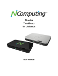
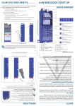
ALE718 Multi Camera LANC Controller User’s Guide Thank you for purchasing our controller product. The following information will help you successfully connect this controller board to your cameras and get it running in your application. Overview This user’s manual covers the ALE718 Multi Camera Controller and the ALE719 LANC Expansion Board. The ALE718 controller (measuring about 3 inches by 3 inches) is designed to control multiple LANCequipped camcorders (most Sony models and some Canon models) simultaneously – meaning that the function command issued from the controller (i.e. POWER ON, RECORD START, etc.) is sent to all connected cameras for simultaneous control. In a dual camera setup, this provides an excellent way to perform 3D (stereoscopic) recording. With more than two cameras, other interesting recording setups can be constructed. The ALE718 includes one ALE719 board as standard equipment to provide connections for up to two cameras. Additional ALE719 boards can be added to this setup to provide additional camera connections – each ALE719 provides connections for two additional cameras that can be controlled by the same ALE718 controller. Each board “stacks” (i.e. plugs into) the previous ALE719 board, providing virtually an unlimited number of camera connections that can all be controlled simultaneously from a single ALE718 controller. The controller operates in two different modes – embedded mode and PC mode. In the embedded mode, the user can simply press one of the on-board buttons to control the camera(s) connected to the controller. In the PC mode, the controller is connected to a personal computer that is used to issue the commands to control the camera(s) connected. (9) Function Buttons ALE718 Controller board LEDs indicating LANC activity ALE719 Expansion boards “Stacking” connectors ALE718 controller with two ALE719 expansion boards connected USB connector for power and PC LANC connections to the cameras Page 2 Using the Controller in Embedded Applications Setting Up Using the supplied LANC cables, connect the controller board to the camera(s) that are to be controlled. Our standard cable has 2.5mm plugs on both ends – plug one side into any available jack on any ALE719 expansion board. The other end of the cable will plug into the camera’s LANC jack. If your camera uses the 10-pin A/V-style connector, you will need to use an adapter to convert the 2.5mm plug to the 10-pin D connector. Check http://www.appliedlogiceng.com/index_files/Page567.htm for details. Camcorders with the “multi” socket require a Sony VMC-AVM1 adapter cable and one of the 10 pin adapters described above. 2.5mm connector 10-pin D connector “Multi” connector Connecting to Power The controller board comes with a standard USB connector that serves two purposes – one is to supply 5 VDC power to the controller and the other is to provide an optional data connection to a PC if you are going to control your adapter from a PC. To use the controller in stand-alone mode (no PC connection), plug any USB adapter into an AC source and into the USB plug on the ALE718 board. PLEASE INSURE that your power adapter outputs +5 VDC only – any other voltage may cause damage to the ALE718. Alternatively, if you are going to use a PC to control the adapter, use any standard USB cable to make a connection between a USB port on your PC and the ALE718. Power to the controller will then be supplied by the PC itself. Page 3 Using the ALE718 with two cameras The following section will describe how to proper use the ALE718 controller with two cameras connected. We will also discuss camera sync disparity, which is important in 3D (stereoscopic) applications. Power On Before powering the controller board on, make sure that the cameras being controlled are connected via the supplied LANC cables. When power is applied to the controller board, the controller will initially go through a software process to determine the sync disparity between the two cameras. This process determines how close the LANC packets are synchronized between the cameras. The controller board measures the amount of time between the start bit of Camera 1 and the start bit of Camera 2. The sync process then displays the result of the sync measurement in two ways: Page 4 The two red LEDs on the ALE718 will blink at the start of each LANC packet on each camera. The left LED shows the start of the LANC packet on the left camera and the right LED shows the start of the LANC packet for the camera plugged into the right LANC jack. Additionally, using our ALE712 Deluxe LANC Control software application (version 1.2 or greater), you can see the exact sync disparity between the cameras in microseconds. Find the CAMERA SYNC box in the upper portion of the window. Press the CHECK SYNC button and the current sync disparity will be displayed in microseconds. Page 5 This information may be important for your operation, especially if you are doing 3D recording. If the sync measurement is unacceptable for your application, the cameras should be powered off using the POWER OFF button, and then powered back on using the POWER ON button. The sync process will then be repeated with the new results displayed on the LEDs and/or the software application. Using the ALE718 with more than two cameras Using the ALE718 with more than two cameras follows the same process as above. Additional ALE719 expansion boards must be installed onto the ALE718 controller to provide the additional camera connection jacks (two per ALE719 board). Each time a LANC command is issued (either by pressing one of the function buttons or by issuing a LANC commend through the USB PC interface), all cameras will be simultaneously sent the LANC command via their respective LANC connections. The sync process as described above will still work for the two cameras plugged into the first ALE719 expansion board – the LEDs will indicate the start of the left and right camera’s LANC packets and the sync disparity between these two cameras will still be available on the software application. DIP switch settings on ALE719 Expansion Boards Each ALE719 Expansion Board contains two DIP switch packs (4 switches to a pack) – each switch pack is used to determine the “address” of the camera connection. The DIP switch on the left side of the ALE719 board controls the camera connected to the LANC jack on the left side of the board and the DIP switch on the right controls the camera connected to the LANC jack on the right side of the board. These DIP switches determine the unique address for each camera that is connected to the ALE718 controller and, therefore must be set to unique values in order to be “seen” properly by the ALE718. If any camera’s DIP switch settings are identical to any other camera DIP switch settings, problems will occur in the operation of the ALE718 controller. Page 6 DIP switch for Left Camera DIP switch for Right camera LANC connector for Left camera LANC connector for Right camera If you ordered your ALE719 Expansion Boards at the same time you ordered your ALE718 from us, all DIP switches will be set by the factory for proper operation. If you purchased an ALE719 Expansion Board by itself to add to an existing ALE718 controller, you will need to make sure that the DIP switches on all ALE719 boards are set to unique positions (i.e. no DIP switches for one camera set to the same setting as another camera. Page 7 Sending LANC commands to the cameras Once the ALE718 is connected to the cameras and powered on, you can begin using the controller to operate the camera(s) connected. Pressing any button on the controller board will simultaneously send the designated LANC command to the camera(s) connected to the controller. From the factory, the buttons on the board are defined as follows: Switch 1 – Zoom In Switch 2 – Zoom Out Switch 3 – Focus Auto/Manual toggle Switch 4 – Focus Far Switch 5 – Focus Near Switch 6 – Record Start/Stop Switch 7 –Photo Capture to Memory Switch 8 -- Power Off Switch 9 – Power On The Zoom In, Zoom Out, Focus Far, and Focus Near buttons can be held down to supply continuous commands to the camera(s) for these functions. Changing the LANC commands assigned to the function buttons The LANC commands designated above are preset in the ALE718’s memory at the factory. If you would like to change these button designations, you can use our ALE718 Programmer Utility application. This is a free Windows app that is available on our web site (www.appliedlogiceng.com). Install this application on your PC using the SETUP program. Once installed, connect a standard USB cable between your PC and the ALE718, then start the application. You will see the following: Page 8 The application will automatically find the ALE718 on the correct COM port and indicate that the process was successful by displaying FOUND ALE718 ON COMx in the message box. If for any reason this process does not work correctly, click on the AUTO-DISCOVER CONTROLLER checkbox to disable it, then manually select the correct COM port using the drop down box, followed by clicking the OPEN button. Once the software is correctly connected to the controller, clicking the READ button will cause the application to poll the ALE718 and display the current function button configuration. To change the LANC command assigned to any button, click the button’s drop down box and select the LANC command desired or that function button. Once all function buttons have been edited for your purpose, click the PROGRAM button. The application will then reprogram the ALE718 with the new function button designations. Page 9 Using the Controller Connected to a PC Installing the Software Driver The software driver required to communicate successfully between your PC and the ALE718 will load automatically when you plug the USB cable into your PC and into the ALE718. You will need an active Internet connection on your PC during this installation. If for any reason the driver fails to install automatically, you can download the appropriate driver from our website before you can connect your PC to the controller board. The driver can be downloaded from http://www.appliedlogiceng.com. Once properly installed, Windows assigns a virtual COM port to this USB connection. This virtual COM port is used by the software on the PC as the communication medium. The driver supports Windows 2000, Windows XP, Windows Vista, Windows 7, and Windows 8 (both 32 and 64 bit versions). Connecting the Controller Board to a PC The controller board has a USB connector for connection to a Personal Computer’s USB port. When using the USB port, you do not need any external power as the controller board draws its power from the USB port itself. When plugged in, the board powers up and then begins running the sync process (see above). When the sync process is complete, the USB port then instantiates on the PC and the virtual COM port is established on the PC. Sending Commands from the PC In order to send LANC commands from your PC to the camera, you must have the ALE Deluxe LANC Controller software (version 1.2 and above) running on your PC. Please see the User’s Guide for our ALE712 Deluxe LANC Controller Software for additional information on operating this software application. Page 10 Troubleshooting No power to ALE718 Controller Check that the ALE718 is properly connected to a +5 VDC power spurce via the USB connector Some cameras are controlled by the ALE718, but some are not Check that all cameras are properly connected to the ALE718 controller If you’ve recently added a new ALE719 Expansion Board, make sure that each camera’s DIP switch pack is set to the proper position (must be unique between cameras) Improper LANC commands sent to cameras Use the ALE718 Utility Application to check that all function buttons are properly configured Page 11