1
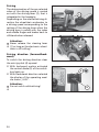
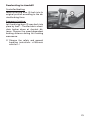
GB
OPERATING MANUAL
OPTIMUS 2 / - 2S
Model 2.322
W e
m o v e
p e o p l e .
Contents
Introduction .................................................................................................. 6
Indications..................................................................................................... 7
Acceptance .................................................................................................... 7
Specifications................................................................................................ 8
Use ................................................................................................................. 8
Adjustment ................................................................................................... 9
Life span ........................................................................................................ 9
Overview ..................................................................................................... 10
Model: 2.322 .......................................................................................................10
Driving behavior ........................................................................................ 11
Functional checks ...............................................................................................11
Brakes .......................................................................................................... 11
Service brake .......................................................................................................11
Braking the electronic wheelchair ...............................................................11
Parking brake .....................................................................................................11
Selection lever.....................................................................................................12
Locking the brake .........................................................................................12
Releasing the brake ......................................................................................12
Drive-/push mode ...............................................................................................13
Selecting the push mode ..............................................................................13
Selecting the motor mode ...........................................................................13
The drum brake ..................................................................................................14
Locking the drum brake ...............................................................................14
Releasing the drum brakes...........................................................................14
Selecting the operation ............................................................................. 15
Pre-operation checks ..........................................................................................17
Charging procedure ......................................................................................18
Operating module ...................................................................................... 19
Function description...........................................................................................19
Positioning the operating module....................................................................19
Horizontal adjustment..................................................................................19
Vertical adjustment .......................................................................................20
2
Remove the operating module .........................................................................21
Fitting of the operating module .......................................................................21
Turning the operating module to the side ......................................................22
Mechanical one hand operation, Code 531 .....................................................23
Switchbox ......................................................................................................23
Driving............................................................................................................24
Curve driving .................................................................................................26
Leg supports ............................................................................................... 27
Calf belt ...............................................................................................................27
Removing / attaching the calf belt ..............................................................27
Foot supports ......................................................................................................28
Folding up the footplates.............................................................................28
Folding down the footplates .......................................................................28
Foot board ..........................................................................................................29
Folding up the foot board ...........................................................................29
Folding down the foot board ......................................................................29
Leg support upper part......................................................................................30
Turning the leg supports to the side ..........................................................30
Removing the leg supports ..........................................................................31
Attaching the leg supports ..........................................................................32
Mechanically height-adjustable leg supports ..................................................33
Lifting the leg supports ................................................................................33
Lowering the leg supports ...........................................................................33
Electric height adjustment of the leg supports ..........................................34
Height adjustment ........................................................................................34
Stump support ....................................................................................................35
Removal .........................................................................................................35
Hanging-in .....................................................................................................35
Height adjustment ........................................................................................35
Angle adjustment .........................................................................................35
Arm supports, code 106 ............................................................................. 36
Remove the arm support ...................................................................................37
Arm support with memory-effect .....................................................................38
Mounting the arm supports .........................................................................38
Adjusting the height of the arm supports ..................................................38
3
Arm support without memory-effect ...............................................................38
Adjustment and assembly of the arm support height ...............................38
Arm supports code 24 - Ergostar seat ...............................................................39
Swivel up the arm supports..........................................................................39
Adjusting the angle of the arm support .....................................................39
Adjusting the height of the arm support ...................................................39
Seat .............................................................................................................. 40
Swivelling up the seat ........................................................................................40
Electrical seat-angle adjustment .......................................................................40
Electrical angle adjustment of the back support .......................................41
Removing the back .......................................................................................41
Mounting the back .......................................................................................41
Seat Ergostar .......................................................................................................42
Adjustment of the back support angle .......................................................42
Lordosis adjustment ......................................................................................42
Ergo Seat .............................................................................................................43
Folding over the back support .....................................................................43
Folding up the back support ........................................................................43
Adjusting the back support angle ...............................................................43
Retaining strap ........................................................................................... 45
Fastening the retaining strap.......................................................................45
Opening the retaining strap ........................................................................45
Adjustment of belt length ...........................................................................45
Head support .............................................................................................. 46
For seating system ERGO Seat ............................................................. 46
For seating system RECARO .......................................................................46
Loading and transportation ...................................................................... 47
Loading ...............................................................................................................47
Passenger transport in handicapped transport vehicles (HTV).......................47
Transport security ...............................................................................................48
4
Maintenance ............................................................................................... 48
Maintenance .......................................................................................................48
Maintenance schedule ..................................................................................49
Batteries ..............................................................................................................51
Fuses ....................................................................................................................52
Replacing the fuses .......................................................................................52
Tyre damage on pneumatic tyres......................................................................52
Lighting ...............................................................................................................53
Adjusting the headlights ..............................................................................53
Headlights......................................................................................................54
Front indicator...............................................................................................55
Rear indicator ................................................................................................56
Back light .......................................................................................................57
Information for the specialist dealer ................................................................58
Programming the driving behaviour...........................................................58
Technical data ............................................................................................. 59
Kilometric performance .....................................................................................59
Hill climbing ability .......................................................................................59
Fuses ....................................................................................................................60
Lighting ...............................................................................................................60
Technical data ............................................................................................. 61
Model 2.322 ........................................................................................................61
Meaning of the labels on the wheelchair ........................................................66
Meaning of the symbols on the type plate ......................................................67
Symbols ...............................................................................................................67
Fault correction .......................................................................................... 68
Inspection certificate ................................................................................. 69
Warranty / Guarantee................................................................................. 70
Inspection certificate for transfer .....................................................................71
5
INTRODUCTION
– the safety and general handling instructions < Electronic vehicles >.
We thank you for the confidence you
have placed in our company by choosing an electronic wheelchair from this
series.
☞ Note:
The model of your selection, fulfils
the wish for mobility and more independence by way of a new styling of
the proven MEYRA-Ortopedia technology.
With all equipment and their accessories the electronic wheelchair offers
the respective adaptation to your disability.
Like any other vehicle, an electric
wheelchair is a technical aid. It is subject to explanations, requires regular
care and can cause danger when used
improperly. The correct handling must
therefore be learned. This manual is
to help you get accustomed to the
handling of the electric wheelchair as
well as to prevent accidents.
☞ Note:
Please note that the illustrated
equipment variants can deviate
from your model.
We have therefore also listed chapters
with options that might not be applicable for your vehicle.
!
Attention:
Read and observe the following
documentation belonging to the
electric wheelchair before first
use:
– this operating manual,
– the operating manual < Operating
module >,
6
Children and juveniles should read
the documentation belonging to
the electronic wheelchair together with their parents respectively
a supervisor or attendant before
first use.
For users with visual impairments the
PDF-files of the above mentioned documents can be accessed on our website < www.meyra-ortopedia.com >.
☞ Contact your specialist dealer when
required.
Alternatively people with visual impairments can have the documentation read out by a helper.
INDICATIONS
ACCEPTANCE
If the following indications occur we
recommend the application of this
mobility product:
All products are checked for faults
in the factory and packed in special
boxes.
☞ Walking disability resp. extremely
☞ Note:
limited walking ability as part of
the basic need to move around in
your own home.
☞ The need to be able to leave home
for a short walk in fresh air or in order to reach the places, commonly
in the perimeter of the home, required to fulfil basic needs.
However, we request that you
check the vehicle for possible
transport damage immediately on
receipt – preferably in the presence
of the carrier.
☞ Note:
The packaging of the electric
wheelchair should be stored for a
further transport that might become necessary.
7
SPECIFICATIONS
USE
The electric wheelchair is an environment-friendly electric vehicle. It was
developed to extend the mobility of
persons with health-related or age-related restrictions.
The electric wheelchair, with attached
leg supports and arm supports, serves
exclusively for the conveyance of one
sitting person. Other pulling or transporting uses do not comply with its
intended purpose.
☞ The model is assigned to user category B (Optimus 2) resp. C (Optimus 2 S) according to the norm
EN12184.
This model is an electronic wheelchair
especially for indoor and outdoor use
on firm, level surfaces.
The electronic wheelchair offers manifold adjustment possibilities to individual vital statistics.
The electronic wheelchair should be
adapted to your needs by a specialist
dealer before the first use. The adaptation will take into account the driving experience, the physical limits of
the user and the main place of use of
the electronic wheelchair.
!
8
Attention:
Always have adaptation and adjustment work carried out by a
specialist dealer.
ADJUSTMENT
LIFE SPAN
The specialist workshop will hand out
the electronic wheelchair to you under consideration of all relevant safety
instructions, ready for operation and
adjusted to your needs.
We expect an average lifespan of
about 5 years for this product, as far
as the product is applied for its designated purpose and all maintenance
and service guidelines.
☞ Note:
☞ We recommend a regular inspec-
The life span of your product depends
upon the frequency of use, the application environment and care.
tion of the electronic wheelchair
adjustment in order to ensure a
long-term optimal provision even
with changing illness/handicap patterns of the user. Especially for children and juveniles an adjustment
every 6 months is recommendable.
☞ We recommend regular medical
The implementation of spare parts
can prolong the life span of the product. As a rule spare parts are available
up to 5 years after production is discontinued.
☞ The indicated life span does not
constitute additional guarantee.
exams in order to ensure safety for
active participation in traffic.
☞ Retrospective adjustments should
be carried out solely by the specialist dealer!
9
OVERVIEW
Model: 2.322
The overview shows the most important components and operating devices of
the electric wheelchair.
1
2
3
14
4
13
5
15
6
16
12
11
17
10
9
8
7
Pos. Description
1
2
3
4
5
6
7
8
9
10
11
12
13
Back support
Arm support
Seat
Leg support
Seat lock
Leg strap
Footplate
Headlight
Drive wheel
Front indicator
Steering wheel
Front transport attachment
Angle adjustment of the back
support
14 Operating module
10
15 Selection lever drive-/push mode
16 Direction indicator light / rear
light
17 Rear transport attachment
DRIVING BEHAVIOR
BRAKES
The fine-tuning to optimise the driving behaviour of the electric wheelchair with the personal situation is to
be done by your specialist dealer or
therapist.
Service brake
The adaptability offers sufficient driving comfort as well as a high operating safety.
You define the speed and direction
yourself with the joystick movements
(driving and steering lever) while
driving as well as the pre-adjusted
maximum final speed of your electric
wheelchair.
The motors work electrically as operating brake and carefully brake the
electronic wheelchair down without
jerks to stillstand.
Braking the electronic wheelchair
For allotted braking of the electric
wheelchair slowly guide the joystick
back to the centre position (zero-setting).
☞ The electronic wheelchair stops in
shortest distance after releasing
the joysticks.
Functional checks
Parking brake
The functions and safety of the electric wheelchair must be checked before the start of each journey.
The parking brakes only work when
the selection lever is in the drive
mode position. They disengage automatically when the wheelchair starts
off. They are disengaged manually by
moving the selection lever to the push
mode position.
☞ For this observe chapter < Inspections before starting to drive > in
the Operating manual of the Operating module.
☞ Therefore observe chapter < Drive/
push mode >.
11
Selection lever
Locking the brake
Swivel the selection lever forward as
far as possible (1).
!
•
Attention:
It is impossible to push the electric
wheelchair when in drive mode.
The brake performance reduces
with
the brake pads are worn.
2
1
If the electric wheelchair demonstrates
an uneven or impaired braking effect,
take it immediately to your specialist
workshop for repair.
Releasing the brake
Therefore first activate the locking
sleeve (2) on the selection lever and
then swivel the selection lever back as
far as possible (3).
!
•
12
Attention:
Do not get into/out of the electronic wheelchair unless it is switched
off and the selection lever has been
set to "drive mode".
Inadvertently knocking the joystick
will set the electric wheelchair in
motion without control! – Danger
of accidents!
3
Drive-/push mode
1
The lever (1) for switching the drive
motors between the drive mode and
push mode is located on the right side
of the electric wheelchair.
!
Attention:
Push the electric wheelchair only
for manoeuvring or in emergency
cases but never on gradients.
2
1
The electric magnetic brakes are
switched off in the push mode.
☞ A braking of the electric wheelchair
is then only possible by switching
to the drive mode. Therefore do
not switch to the push mode on
gradients.
Selecting the push mode
1. Switch off the operating module
because the pushing will otherwise
be made difficult by the electric
system.
3
2. Pull the locking sleeve (2) up and
then push the selection lever to
the rear ( 3).
☞ The electric wheelchair can now be
pushed.
Selecting the motor mode
1. Push the selection lever to the front
(1) until it audibly latches.
2. Switch the operating module on.
☞ The electric wheelchair is now
ready for operation again.
13
The drum brake
The optional drum brake only serves
as a parking brake, resp. emergency
brake.
The brake lever to activate the drum
brake is located opposite of the selection lever drive- / push mode of the
safety spring pressure brake. – Also
view stickers.
!
1
Attention:
While driving only activate in case
of emergency. – Danger of accidents!
Locking the drum brake
Therefore swivel the brake lever at
the side as far back as possible (1).
!
•
Attention:
Your electronic wheelchair may
not let itself be pushed.
The brake performance reduces
with
the brake pads are worn.
With reducing brake function immediately have the electric wheelchair
serviced in a specialist workshop.
2
Releasing the drum brakes
For this swivel the brake lever at the
side as far forward as possible (2).
!
Attention:
Only transfer into or out of the
electric wheelchair when it is
turned off and the selection lever
drive- / push mode is in the „drive“
position!
Inadvertently knocking the joystick
will set the electric wheelchair in
motion without control! – Danger
of accidents!
14
SELECTING THE OPERATION
In order to obtain operational readiness of the electric wheelchair the following directions are to be carried out
in the indicated order.
☞ Note:
1
Charge the drive batteries via the
operating module before the first
journey.
1. Shift to drive mode
Move the drive motors to the drive
mode position. – Push the selection
lever to the front (1) until it audibly
latches.
2
2. Check the tight seat of the battery fuse
Blade-type fuse:
The flat fuse (2) for the battery/main
current must fit tightly in the fuse
holder underneath the battery cover.
15
3. Checking the position of the
operating module
4
The operating module should be positioned in such a way that you can
comfortably and safely steer the electric wheelchair.
Horizontal adjustment:
After loosening the clamping screw
(3) the operating module can be adjusted horizontally.
!
Attention:
Tighten the
again.
adjusting
screws
Vertical adjustment:
☞ Therefore observe chapter < Positioning the operating module >.
4. Switching the operating module on
Press the ON/OFF-key on the key field
of the control panel.
☞ Note:
Only actuate the joystick (4) after
the self-test of the electronics has
been completed!
☞ Key-lock function:
☞ The key-lock function enables you
to secure the electric wheelchair
against unauthorised use.
☞ Observe user manual < Operating module >, chapter < Key function >.
16
3
3
Pre-operation checks
Before starting to drive, the following
should be checked:
☞ the battery charge level,
☞ the pre-selected top speed setting.
– Therefore observe operation manual < Operating module >.
☞ Note:
– Only transfer to and from the electronic wheelchair when the electronic wheelchair is switched off
and the brake release lever has
been placed into the forward position!
– Inadvertently knocking the joystick will set the electric wheelchair
in motion without control! – Danger of accidents!
17
Charging procedure
1. Switch the operating module off.
The selection lever should be in the
drive mode position.
2. Insert the battery charger plug into
the operating module (1).
!
Attention:
Do not insert any objects other
than the battery charger plug into
the battery charging socket. – Danger of short circuit!
1
3. Switch on the battery charger, respectively, plug the mains plug of
the battery charger into a convenient mains socket. The battery is
now charging.
☞ The charging process only runs
with an intact battery fuse (2)!
4. Disconnect the battery charger
from the mains socket at the end
of the charging process and then
pull the charging plug out of the
operating module.
18
2
OPERATING MODULE
Function description
You will find a detailed description of
the keys and symbols in the operating
manual for < Operating module >.
1
The position of the operating module
can be adjusted to suit the individual
size of the user. The control unit can
also be detached for transportation or
storage and can be laid on the seat or
stored separately.
!
Attention:
Switch off the operating module
before adjusting/removing it.
1
Positioning the operating
module
Horizontal adjustment
Slacken the clamping screw (1) for
horizontal adjustment. Slide the operating module into the desired position and in doing so carefully guide
the cable along. Retighten the clamping screw again securely.
1
19
Vertical adjustment
With the optional height adjustable
operating module adapter the operating module can be adjusted in
height.
Hold onto the operating module and
loosen the clamping screw (3) for vertical adjustment (1). Move the operating module into the desired position.
Afterwards retighten the clamping
screw (3) securely.
20
3
1
Remove the operating module
To remove the control unit, slacken
the clamping screw (1). Pull the operating module to the front.
☞ Carefully route the cable when do-
1
ing this.
!
Attention:
If possible do not disconnect the
connector cable when removing
the operating module since the
plug is only designed for maintenance measures.
☞ For removing the operating module for maintenance observe chapter < Disconnecting the connector
cable of the operating module >.
1
Fitting of the operating
module
Insert the operating module into its
clamping device. Tighten the clamping screw (1).
☞ Carefully route the cable when doing this.
1
21
Turning the operating module to the side
With the optional swivel away operating module adapter (1) the operating
module can be swivelled back to the
side (2) so that it is located parallel to
the arm support. This makes it possible, for example:
1
– to drive closer to a table,
– Remove the operating module
more easily.
Swivel the operating module forward
again for regular drive mode (1), until the magnetic connection engages
resp. the chinch locks into place.
☞ Note:
☞ The power of the magnets (3) can
be reduced, for example with tape
on top of the magnets, for easier
swivelling of the operating module.
2
☞ Should the operating module be
positioned too close to the arm
support, move it forward before
swivelling.
!
22
Attention:
Do not grab into the area of the
cross brace. – Danger of squashing!
3
3
Mechanical one hand operation, Code 531
In this version the driving direction is
not defined servo-electric, but manually with a steering lever (1).
In order to be able to operate all driving functions with one hand while
driving, these are integrated into a
switchbox (2) on the hand lever. The
basic function such as on, light, warning lights as well as the speed display
etc. are carried out on the operating
module.
2
3
1
2
☞ Note:
Observe the operating manual
< Operating module > .
!
Attention:
Do not move the driving lever (3)
out of the zero position before
the self-test of the electronic has
ended. – The signal bar of the LEDdisplay stops blinking. See Fault
clearance part of Service section if
blinking continues.
4
Switchbox
The following functions can be selected via the mini-joystick (4) of the
switchbox (2), on the steering lever
(1):
Left indicator
Steer the mini-joystick to the left.
Right indicator
Steer the mini-joystick to the right.
Horn sound
Steer the mini-joystick down.
Travel direction reversing
Steer the mini-joystick upward.
23
Driving
The determination of the pre-selected
value of the driving speed is carried
out with the driving lever (3), that is
integrated in the handgrip.
Depending on the selected driving direction the wheelchair accelerates to
a driving speed corresponding to the
setting of the driving lever when the
driving lever is pulled with the index
and middle finger and brakes back to
stillstand when released.
!
Attention:
Never release the steering lever
(1) as long as the electronic wheelchair is still rolling!
3
1
Driving direction (forward/backward)
To switch the driving direction steer
the mini-joystick (4) upward.
☞ With backward motion activated
the control diode (5) of the switchbox lights up.
☞ With backwards direction selected
the display of the operating module shows „UUU“.
!
24
Attention:
Do not switch while driving!
5
4
Decelerating to standstill
Controlled braking:
Lead the driving lever (3) back into its
original position according to the desired braking force.
3
Emergency braking:
Let the driving lever (3) snap back into
place by itself. – The electronic wheelchair brakes down at shortest distance. Observe the speed dependant
braking distance during this braking
manoeuvre.
☞ Observe the safety and general
handling instructions < Electronic
vehicles > !
25
Curve driving
Steeling lever on the right side of
the vehicle
To conduct a left turn the steering lever (1) is swivelled forward in driving
direction out of the centre position
and depending on the desired curve
angle of the wheels (1), for a right
turn accordingly to the back (2).
Steeling lever on the left side of
the vehicle
To conduct a right turn the steering
lever (1) is swivelled forward in driving direction out of the centre position and depending on the desired
curve angle of the wheels, for a left
turn accordingly to the back.
☞ Note:
The driving safety especially of
manually directly steered electronic wheelchairs generally depends
on the sensitive and practised behaviour during the steering procedure.
!
Attention:
Jerky steering movements are to be
refrained from especially in higher
driving speeds. – Risk of overturning!
☞ Note:
☞ Electronic aids (e.g. curve speed
reduction) can only provide supporting safety due to the laws of
physics.
☞ Observe that the electronic wheelchair will return accelerate back to
the predetermined driving speed
when coming out of the curve.
26
1
1
LEG SUPPORTS
!
Attention:
Do not use the leg supports to lift
or carry the electronic wheelchair.
•
Lift the feet, respectively place
them on the footplates before
each movement of the electric
wheelchair.
•
The operating module is to be
switched off:
1
– before placing the feet on the
floor,
– to remove the calf belt and the
leg support,
– before folding up the footplates.
Calf belt
2
The calf belt (1) prevents the feet from
sliding off the back of the footplates.
It is guided around special ligament
(2) and adjusted in length with a velcro fastener.
Removing / attaching the calf belt
Removing / attaching of the calf belt
is achieved by pulling it upward or
lowering it.
!
Attention:
Do not drive without the calf
belt. – The leg strap is omitted for
height adjustable leg supports and
is replaced by a leg padding.
27
Foot supports
Folding up the footplates
The footplates are to be folded up
for entering or exiting the wheelchair
(1).
– Remove both feet from the footplates.
– Fold both foot plates up toward
the side (1).
☞ Check the locking points!
1
Folding down the footplates
The footplates are to be lowered before starting to drive.
– For this swivel the footplates inward and down (2).
2
28
Foot board
The footboard (2) can be folded up to
one side (3).
Folding up the foot board
For an unobstructed foot area, fold
up the left side of the foot board to
the right as far as it will go (3).
2
Folding down the foot board
Fold down the left side of the foot
board until it rests on the foot board
holder (4).
3
4
29
Leg support upper part
Turning the leg supports to the
side
1
For less length of the electronic wheelchair the leg supports can be swivelled
inward.
– Before swivelling the leg support
loosen or remove the calf belt on
one side.
– Fold up the foot plates.
– Afterwards pull or press the respective locking lever (1) and swivel the
corresponding leg support inward/
outward.
!
30
Attention:
Leg support turned to the side are
released automatically and can
easily come off. Note this when
handling (e.g. transport).
1
Removing the leg supports
For easy transfer into and out of the
electronic wheelchair as well as a reduced length (important for transport) the leg supports can be removed
(1).
☞ Note:
Before swivelling the leg support
remove the calf belt on one side.
1
– Remove both feet from the footplates.
– Fold the footplates outward and
up.
– Pull or press the locking lever backward (2).
2
– First swivel the leg support sideways and then remove them toward the top (1).
☞ Watch for jamming areas!
!
Attention:
With the electrically height adjustable leg supports removed, only
the now visible electric contact in
the frame tube is to be protected
from dampness, wetness as well as
dust and dirt! – Function error of
the electrical adjustment.
2
2
31
Attaching the leg supports
Place the leg support, slightly swivelled off sideways, from the top onto
the receptacle pins (1) and swivel forward until the lock audibly engages.
☞ Note:
After swivelling the leg support inward again do not forget to check
the corresponding locking device.
1
In required replace the calf belt.
☞ Conduct a function test of the electric leg supports!
1
32
Mechanically height-adjustable leg supports
1
When seated in the wheelchair, ask a
carer to raise the leg support to the
desired level. The length adjustment
is given through the turning point at
the height of the knee joint.
!
Attention:
Never put the free hand into the
adjustment mechanism while adjusting the height adjustable leg
support.
Lifting the leg supports
1. While seated have the leg support
secured by an attendant against
falling down.
2. Have the leg support raised to the
desired level by an aid and release
the clamping lever (1).
3. After the adjustment retighten the
clamping lever (1).
Lowering the leg supports
1. Have an aid lift the lower leg in order to relieve the leg support for
lowering.
2. Loosen the clamping lever (1) and
have the leg support lowered slowly to the desired level by an aid.
!
Attention:
Do not let the leg support drop
on its own weight. – Danger of
squashing!
3. After the adjustment retighten the
clamping lever (1).
33
Electric height adjustment of the
leg supports
Electric contact is automatically established when attaching the leg support
with automatic length alignment.
!
Attention:
Do not reach into the adjustment
mechanism. – Danger of crushing!
1
Height adjustment
For the height adjustment of the leg
supports view users manual < Operating module >.
– Whilst sitting in the wheelchair,
raise or lower the leg support to
the desired height via the operating module.
!
Attention:
Observe the safety and general
handling instructions < Electronic
vehicles >!
Swivelling the leg support upward
The leg support swivels upward by
max. 80°.
34
2
Stump support
Removal
First pull back or press the locking lever (1). Then swivel out the leg stump
support and pull it off in an upward
direction.
1
Hanging-in
With the leg stump support in a
swivelled-aside position, hang it in
and then swivel it to the front until
the locking device audibly locks into
place.
☞ Check for a correct locking of the
2
locking device!
Height adjustment
☞ Secure the leg stump support
against unintentional lowering.
Loosen the clamping screw (2) and
adjust the desired height. Afterwards
retighten the clamping screw (2).
Angle adjustment
☞ Secure the leg stump support
against unintentional lowering.
Loosen the clamping lever (3) and set
the desired angle. Afterwards retighten the clamping lever (3).
3
35
ARM SUPPORTS, CODE
106
The removable arm supports [1]+[2]
can be adjusted in height to the demands of the user.
!
Attention:
Do not use the arm supports to lift
or carry the wheelchair.
•
Do not drive without the arm supports!
•
During adjustment the maximum
arm support height is reached
when a mark (3) becomes visible
on the inert tube.
•
Ensure the tight fit of the clamping
screw (4) in order to prevent the
arm support from sliding down.
☞ Note:
1
4
2
Danger of jamming when adjusting the height of the arm supports
if the cushions are in a deep setting!
3
36
Remove the arm support
– Remove the arm support in an upwards direction (5). – Therefore
loosen the clamping screw (4) of
the clamping guide.
☞ Note:
The operating module must be removed first if the arm support on
the control side is to be detached.
5
To remove the control unit, loosen the
respective clamping screw (6).
☞ Note:
6
Carefully route the cable when doing this.
4
37
Arm support with memoryeffect
Mounting the arm supports
2
– Insert the arm support (1) as far as
possible into the respective guide
(6) and tighten the clamping screw
(4).
!
Attention:
Danger of crushing!
1
Adjusting the height of the arm
supports
4
6
Loosen the clamping screw (2), slide
the arm support to the desired height
and retighten the clamping screw (2).
!
Attention:
Before loosening the clamping
screw (2) secure the arm support
against falling down with your
hand. – Danger of jamming if the
clamping screw is not turned in
completely (2)!
Arm support without memory-effect
Adjustment and assembly of the
arm support height
– Insert the arm support (3) into the
respective guide.
– Afterwards hold the arm support
at the desired height and then
tighten the clamping screw (5).
38
5
3
Arm supports code 24 - Ergostar seat
Swivel up the arm supports
The arm support can be swivelled up
for an easier transfer to/from the seat
(2).
Adjusting the angle of the arm
support
2
By turning the adjustment wheel (3)
the angle of the arm support can be
adjusted.
Adjusting the height of the arm
support
The height of the arm support can be
adjusted in three steps by repositioning on the back support (4).
3
4
39
SEAT
Swivelling up the seat
☞ Note:
☞ Remove the leg supports if necessary.
1
☞ Always remove the electrical leg
supports.
☞ Grab under the front edge of the
seat cushion for upward swivelling.
!
Attention:
Do not hold onto the leg supports
to swivel the seat up!
– To swivel the seat upward, first
press the seat locking lever upward
(1) the swivel the seat unit toward
the back and up (2).
Electrical seat-angle adjustment
For the electrical seat angle adjustment also view the operating manual
< Operating module >.
!
•
40
Attention:
Do not grab into the adjustment
area. – Danger of crushing!
Observe the safety and general
handling instructions < Electronic
vehicles >!
2
Electrical angle adjustment of the
back support
The angle adjustment of the back support is done through the operating
module.
☞ Observe the operating manual
1
< operating module >.
!
Attention:
It is to be ensured that no clothing pulls itself between the handwheel and back shell (1) during the
adjustment!
Removing the back
First loosen the screwed connections
(2) on both sides before removing the
back support.
Afterwards first push the back support forward before removing it toward the top (3).
4
2
☞ It is to be ensured that no screws
(2) are lost.
Mounting the back
To mount the back support first place
it into the brackets from the top and
then push it toward the back (4).
Afterwards tighten the screws (2) on
both sides.
3
☞ Check to ensure that the back is secure!
41
Seat Ergostar
Adjustment of the back support
angle
To adjust the angle of the back support the locking lever (2) must be
pressed downward.
Let the locking lever latch at the next
latching position after having adjusted the back support angle (1).
1
☞ Note:
Check the lock of the back support.
2
Lordosis adjustment
To adjust the lordosis support turn the
hand wheel (3) counter-clockwise into
the desired position.
3
42
Ergo Seat
The back support can be folded down
for storage or transport.
☞ Note:
1
For better demonstration of the
wire cable (1) the back support is
shown without cushion.
Folding over the back support
– If required remove the seat cushion (velcro fastener).
– Disengage the back support by
pulling or pressing the wire cable
(1) at its centre and fold it onto the
seat (2).
3
Folding up the back support
– For this raise the back support and
pull the pressure bolts inward by
pulling or pressing on the wire cable (1).
– Release the wire cable in order to
lock the back support in the desired position (3). – The pressure
bolt must audibly lock into place.
– If required replace the seat cushion.
☞ Note:
☞ The greasing of the thrust bolts is
recommended for an easier latching of the back support.
2
Adjusting the back support angle
– Unlock the back support by pulling
or pressing the centre of the wire
cable (1).
– Release the wire cable in order to
lock the back support in the desired position (3). – The pressure
bolt must audibly lock into place.
☞ Check the lock of the back support.
☞ Check the lock of the back support.
43
Electrical back support adjustment
The back support (1) is electrically adjustable.
☞ Note:
Herefore view the operating manual < Operating module >.
!
Attention:
Only adjust the back support when
the wheelchair is standing on a
level surface. A danger of tipping
over exists on gradients!
1
Folding down the electrically adjustable back support
To fold the electrically adjustable back
support (2) down, first press the release button (3), then remove the pin
(4).
2
☞ Keep the back support in position
with one hand at the pushing handle.
4
Afterwards fold the back support
down (2).
☞ Reinsert the pin (4) in order to prevent loss.
Check the locking device after folding
the back support up and reinserting
the pin.
☞ Keep the pin clean at all times for
flawless function.
44
3
RETAINING STRAP
5
The retaining strap serves to strap in
a person sitting in the electric wheelchair.
3
2
– Additional stabilisation of the sitting position.
– Prevents the user from sliding forwards out of the electric wheelchair.
– Continuous adjustment to suit the
user’s needs.
The seat belt is screwed on, from the
outer side, at the respective back support holder.
☞ Note:
The retrospective assembly of a retaining strap is only to be carried
out by a specialist workshop!
!
Attention:
The retaining strap is not part of
the retaining system for the wheelchair and/or user during transport
in a handicapped vehicle.
Fastening the retaining strap
– Pull both belt halves to the front
and slide the catch halves together
so that they latch together (1).
4
1
Opening the retaining strap
– For this press the red release button (2) in the lock.
Adjustment of belt length
☞ Note:
The retaining strap should not be
pulled too tight.
– Depending on the version hold the
buckle or the latch (3) at a right angle to the strap.
– Push or pull the strap (4) in the respective direction in order to extend or shorten the strap.
– Absorb excessive strap by repositioning the plastic slider (5).
☞ Then carry out a pull test.
!
Attention:
Make sure that no objects are
trapped between belt and the
body! – Thus you avoid painful
pressure points.
45
HEAD SUPPORT
The head support is swivel/proof,
height- and depth adjustable and removable.
!
Attention:
We recommend the fitting of two
rear-view mirrors for driving with a
head support.
1
For seating system ERGO Seat
The head support can be detached or
adjusted in height after the clamping
lever (1) has been slackened.
!
Attention:
The maximum height adjustment
is indicated by the marking!
For seating system RECARO
The head support can be adjusted in
height by sliding it up or down.
☞ After opening the lock (2) push or
pull the head support to the next
engagement point.
46
2
LOADING AND TRANSPORTATION
☞ Do not use the back support, leg
supports, arm supports or revetments to lift the electric wheelchair!
!
Passenger transport in
handicapped transport vehicles (HTV)
To determine if your electric wheelchair is approved as a seat for transport inside an HTV, please look at the
type plate.
Attention:
The electronic wheelchair must be
switched off before lifting!
Loading
The electric wheelchair can be loaded
with the aid of ramps or lifting platforms.
The product is approved
as a seat within an HTV.
X
The product is not approved as a seat within
an HTV.
☞ Note:
Observe safety and general handling instructions < Electronic vehicles > chapter < Ramp and lifting
platforms >.
47
Transport security
The electric wheelchair is only to be
secured through the securing points
(1) and (2).
☞ The anchor positions are marked
with the symbol (3).
1
☞ The procedure for securing the
electric wheelchair can be read in
the document < Safety and general handling instruction electronic
vehicles > chapter < Transport in
motor vehicles or with conveyors >
.
2
MAINTENANCE
An incorrect or neglected cleaning
and maintenance results in a limitation of the product liability.
Maintenance
The following maintenance Instruction gives you a guide for carrying out
the maintenance work.
☞ They do not give information
about the actual extent of work
required on the vehicle.
48
3
Maintenance schedule
WHEN
WHAT
REMARK
Before starting out
General
Carry out test yourself
or with a helper.
Test for faultless operation.
Checking the magnetic brake
Carry out test yourself
or with a helper.
Switch the selection lever drive- / push mode
to drive mode.
If the wheelchair cam
be pushed have the
brakes repaired immediately in a specialist
workshop.
– Danger of accidents!
Especially before driving in the dark
Lighting
Carry out test yourself
or with a helper.
Replace defective
bulbs immediately.
Every 2 weeks
(depending on distance
covered)
Check air pressure of
the tyres
Check the light- and
indicator signal equipment as well as reflectors for immaculate
performance
Tyre filling pressure:
2.5 bar = 36 psi
Adjustment screws
Screws and nuts are to
be checked for tight
fit.
Carry out test yourself
or with a helper.
Use a tyre gauge.
Carry out test yourself
or with a helper.
Retighten the loosened
adjustment screws.
Contact specialist workshop upon demand.
49
WHEN
WHAT
REMARK
Every 6-8 weeks
(depending on distance
covered)
Wheel attachments
Do it yourself or with
the aid of a helper.
Screws and nuts are to
be checked for tight fit
Securely tighten any
loosened wheel nuts or
screws and retighten
again after 10 operating hours or resp.
50 km.
Contact specialist workshop upon demand.
Every 2 months
(depending on distance
covered)
Check tyre profile
Every 6 months
(depending on frequency of use)
Check:
Minimum tread = 1
mm
Carry out a visual check
yourself or with an aid.
If the tyre profile is
worn down or if the
tyre is damaged, consult a specialist workshop for repairs.
– Cleanness.
See Care.
– General condition.
See Repairs.
Do it yourself or with
the aid of a helper.
Manufacturer
mendation:
recom-
Every 12 months
(depending on frequency of use)
50
Safety inspection
– Vehicle
– Battery charger
To be carried out by
the specialist dealer.
Batteries
Charging the drive batteries
– Insert the charger plug into the
battery charging socket (1) of the
operating module.
1
– Afterwards plug the mains plug of
the charger into a corresponding
outlet.
☞ The battery is now charging.
☞ Therefore also observe the operating manual of the charger!
!
•
Attention:
Do not insert any objects other
than the charging plug suppliet
with the electronic wheelchair into
the battery charger. – Danger of
short circuit!
2
Do not insert charging plugs on
other electric wheelchairs into the
battery socket!
☞ Note:
☞ The charging procedure only runs
with an intact mains/battery fuse
(2)!
☞ After the charging has been completed first separate the battery
charger from the power supply and
afterward pull the battery charging plug from the charging socket.
Maintenance the batteries
☞ Therefore observe the separate
maintenance instruction!
51
Fuses
Replacing the fuses
Before replacing fuses, park the electronic wheelchair on a level surface
and move the selection lever to the
drive mode position to prevent the
wheelchair from moving. Switch off
the operating module.
!
1
Attention:
Only replace the safety fuse with a
safety fuse of the same type!
New safety fuses are available at all
petrol stations.
☞ Note:
If the safety fuse blows again, take
the battery to a specialist dealer
for repair.
2
Fuse
Mains-/battery fuse (1)
The flat fuse for the main / battery
current is located in the fuse holder
under the seat, on top of the batteries (2).
☞ Note:
☞ Therefore
observe subchapter
< Battery maintenance > as well as
chapter < Technical data >.
52
Tyre damage on pneumatic
tyres
☞ For repairing tyre damage we recommend the use of a foam cartridge that is available in speciality shops. – Afterwards look up a
specialist workshop as soon as possible.
Lighting
☞ Note:
If a turn-signal bulb is defective,
the remaining one blinks at double
frequency.
☞ When replacing always use bulbs
with the same performance data.
1
Adjusting the headlights
Vertical alignment
The headlights should be set in such
a way that the light cone is visible on
the road. – The lower edge of the light
cone should be set at distance of 3 meters to the front of the wheelchair.
☞ Note:
The headlights might need to be
readjusted after adjustment of the
seat angle.
Press in the dispersion disc (1) at the
upper or lower edge in order to adjust
the headlights.
53
Headlights
Filament bulb:
6V/2.4W PX13.5s
☞ Note:
Use a dry cloth to hold the glass
body of the new filament bulb.
Removal
1
– Switch off the operating module.
– Pull the mains-/battery fuse.
– Turn the rear lamp housing counter-clockwise by about 15° (1) and
remove it (2). – In doing so hold
onto the dispersion disc to prevent
it from also turning.
– Pull the defective bulb out of the
dispersion disc.
2
Mounting
– Insert the new bulb into the dispersion disc (2).
☞ Note:
Do not touch the halogen bulb
with bare hands.
– Place the rear lamp housing onto
the dispersion disc with an about
15° counter-clockwise turn (1) and
turn clockwise about 15° to let it
lock into place (3). – In doing so
hold onto the dispersion disc to
prevent it from also turning.
54
3
Front indicator
Filament bulb:
12V/21W BAy 9s
6
☞ Note:
3
For removal or renewing the bulbs,
wrap the glass body for example in
a clean, dry paper strip.
2
Removal
– Switch off the operating module.
5
– Pull the mains-/battery fuse.
– Lever off one of the two frontal
locking springs (3) or (4). – Therefore press a small slot screw driver
into one of the two lateral slots (5)
and the wedge off the dispersion
disc (6) carefully upward (7).
– Press the faulty spherical bulb
slightly inwards, turn and remove
from the socket.
5
4
7
Mounting
– Insert a new spherical bulb. – Push
the side pins (bayonet catch) into
the recesses of the bulb holder,
press lightly against the spring and
then turn the bulb until the bayonet catch clicks into place.
– Mount the lens. – Therefore first
insert the rear spring (4), then press
down the dispersion disc (6) (2).
☞ The locking device of the front
spring (3) must audibly engage.
55
Rear indicator
Filament bulb:
12 V / P21W BA15s
☞ Note:
Use a dry cloth to hold the glass
body of the new filament bulb.
2
Removal
1
– Switch off the operating module.
– Pull the mains-/battery fuse.
– Undo the securing screw (2) and
remove the lens (3).
4
– Press the defective spherical bulb
(4) lightly into the holder against
the spring and then turn the bulb
and pull it out of the bulb holder.
Mounting
– Insert a new spherical bulb. – Push
the side pins (bayonet catch) into
the frame, exert slight pressure
against the spring and turn until
the bayonet catch clicks into place
(4).
– Mount the lens. – Press in the lens
and fasten it with the securing
screws (1).
56
3
Back light
Festoon bulb:
6 V / C5W S8.5
☞ Note:
Use a dry cloth to hold the glass
body of the new filament bulb.
Removal
2
1
– Switch off the operating module.
– Pull the mains-/battery fuse.
– Undo the securing screw (2) and
remove the lens (3).
– Press the defective festoon bulb (4)
against the holding pin and then
pull it out of the holder.
Mounting
– Insert the new festoon bulb (4).
– Press one tip into the hole in the
holding pin and then press the
other tip into the hole of the other
holding pin (4).
3
4
– Mount the lens. – Press in the lens
and fasten it with the securing
screws (1).
57
Information for the specialist dealer
A service manual containing a check
list for the annual inspection is available on request.
The functional tests necessary for the
inspection are listed in the check list.
They are a guide for the performance
of the inspection work.
☞ Note:
It does not outline the actual scope
of the necessary work which can
only be ascertained by an inspection of the vehicle.
Programming the driving behaviour
The driving behaviour of the electronic wheelchair can be adjusted through
the programming device.
☞ Therefore observe the respective
< Service manual >.
The driving features of the electronic wheelchair should be adjusted to
the individual requirements and the
learning process of the respective user
at regular intervals.
☞ The programming must be special-
After the successful completion of
an annual inspection the inspection
should be recorded in the operating
manual.
ly tailored to the user. The capacity
of reaction, the constitution as well
as physical and psychical abilities
are to be considered. A talk with
the doctor or therapist can be very
helpful.
A template for additional inspection
certificates can be copied from the
service manual when needed. It then
has to be added to the user manual.
Attention:
Any change to the manufacturer
set programming may result in an
increased danger of accidents.
!
☞ Possible danger of tilting in curves.
58
TECHNICAL DATA
The kilometric performance is greatly
reduced by:
Kilometric performance
– frequent uphill driving,
Kilometric performance depends to a
large extent on the following factors:
– poor drive battery charge condition.
– battery condition,
– low ambient temperature
(e.g. in winter),
– weight of the driver,
– driving speed,
– frequent starting and stopping
(e.g. in town traffic),
– driving style,
– aged, sulphated drive batteries,
– road surface condition,
– frequently necessary steering manoeuvres,
– driving conditions,
– ambient temperature.
The nominal values given by us are realistic under the following conditions:
– Ambient temperature of 20 °C.
– 100 % rated drive battery capacity
as per the DIN standard.
– new condition of the drive batteries with more than 5 charging cycles.
– Nominal load of 75 kg.
– reduced driving speed (especially
at walking speed).
In practical use, the kilometric performance under 'normal conditions' is
then reduced to approx. 80 % – 40 %
of the nominal value.
Hill climbing ability
Gradients in excess of the permitted
values (e.g. ramps) should for safety reasons only be driven when the
wheelchair is empty!
– Without repeated acceleration.
– Level, firm driving surface.
59
Fuses
☞ Hereto observe chapter < Fuses >.
Mains-/battery fuse: ................................................................ 100 A
Lighting
Headlight bulb (Halogen):...... Filament bulb 6 V / 2.4 W PX 13.5s
Rear light: ............................................. Festoon bulb 6V/C5W S8.5
Rear indicator: .........................Filament bulb 12 V / P 21W BA 15s
Front indicator: ..........................Filament bulb 12 V / 10 W BA 15s
Tools
The following tools are needed to replace the lightbulbs:
Phillips screwdriver ..................................................................... Size PH 1 resp. PZ 1
60
TECHNICAL DATA
Model 2.322
All data within the following table relates to the standard version of the stated
model.
Dimensional tolerance ± 1.5 cm, ± 2°.
Model: .................................................................Electric wheelchair model 2.322
Type plate: ...................................................................rear right on the main frame
Class of use as per DIN EN 12184: ........................... B - Optimus 2 / C - Optimus 2 S
Life span: .......................................................................................................... 5 years
Electrical system:
Drive control: ...................................................................................................24 Volt
Main fuse:........................................................................................................... 100 A
Lighting: ......................................................................................................6 / 12 Volt
Dimensions with Ergoseat (Code 948 / 950 without head support):
Length incl. footplates: ............................................................................... 1190 mm
General width: ............................................................................................... 680 mm
Height: ......................................................................................................... 1100 mm
Seat depth (min. / max.): ............................................................................45 / 49 cm
Seat depth (manufacturers setting): ................................................................49 cm
Seat width with code 43 (min. / max.): .....................................................38 / 50 cm
Seat width with code 43 (manufacturers setting): .........................................43 cm
Seat width with code 48 (min. / max.): .....................................................48 / 56 cm
Seat width with code 48 (manufacturers setting): .........................................48 cm
Seat height: ........................................................................................................58 cm
Seat inclination (min. / max.): .........................................................................5° / 20°
Seat inclination (manufacturers setting): .............................................................. 5°
Back support height: .........................................................................................54 cm
Arm support height from upper edge of seat (min. / max.): ..................17 / 27 cm
Transport dimensions with Ergoseat (without leg supports, without head
support):
Length:.......................................................................................................... 1030 mm
Width: ............................................................................................................ 680 mm
Height (Back support folded forward onto the seat):................................ 780 mm
61
Dimensions with seat Ergostar (Code 961 without head support):
Length incl. footplates: ............................................................................... 1190 mm
General width: ............................................................................................... 680 mm
Height: ......................................................................................................... 1170 mm
Seat depth: .........................................................................................................50 cm
Seat width with code 24: ..................................................................................50 cm
Seat width with code 106 (min. / max.): ...................................................43 / 56 cm
Seat width with code 106 (manufacturers setting): .......................................50 cm
Seat height: ........................................................................................................59 cm
Seat inclination (min. / max.): .........................................................................7° / 22°
Seat inclination (manufacturers setting): .............................................................. 7°
Back support height: .........................................................................................64 cm
Arm support height from upper edge of seat
with code 24 (min. / max.):.........................................................................21 / 25 cm
with code 106 (min. / max.): ......................................................................15 / 25 cm
Transport dimensions with seat Ergostar (without leg supports, without
head support):
Length (back support toward the front): .................................................. 1030 mm
Length (back support toward the back): ................................................... 1340 mm
Width: ............................................................................................................ 680 mm
Height (back support toward the front):..................................................... 950 mm
Height (back support toward the back): ..................................................... 720 mm
Dimensions with seat Recaro:
Length incl. footplates: ............................................................................... 1190 mm
General width: ............................................................................................... 680 mm
Height (min. / max.): ......................................................................... 1300 / 1360 mm
Height (without head support): ................................................................. 1130 mm
Seat depth: .........................................................................................................48 cm
Seat width (min. / max.): ............................................................................46 / 56 cm
Seat width (manufacturers setting): ................................................................46 cm
Seat height: ........................................................................................................63 cm
Seat inclination (min. / max.): .......................................................................20° / 35°
Seat inclination (manufacturers setting): ............................................................ 20°
Back support height (with head support) (min. / max.): .........................81 / 87 cm
Back support height: .........................................................................................64 cm
Arm support height from upper edge of seat (min. / max.): ..................18 / 28 cm
62
Transport dimensions with seat Recaro (without leg supports, without head
support):
Length (back support toward the front): .................................................. 1030 mm
Length (back support toward the back): ................................................... 1260 mm
Width: ............................................................................................................ 680 mm
Height (back support toward the front):..................................................... 900 mm
Height (back support toward the back): ..................................................... 800 mm
Tyres:
Steering wheel (rear):................................................... 4.00 – 5 (12.5“ = ø 320 mm)
Drive wheel (front): ................................................. 5.30/4.50 – 6 (14“ = ø 360 mm)
Tyre filling pressure:
Steering wheel: ................................................................................... 2.5 bar (35 psi)
Drive wheel: ........................................................................................ 2.5 bar (35 psi)
Climatic data:
Ambient temperature: .................................................................... -25 °C to +50 °C
Storage temperature with drive batteries: .................................... -25 °C to +50 °C
Storage temperature without drive batteries:............................... -40 °C to +65° C
Drive batteries:
Drive batteries, sealed: ....................................... 2 x 12 V 50 Ah (5 h) / 60 Ah (20 h)
Drive batteries, sealed: ................................... 2 x 12 V 100 Ah (5 h) / 110 Ah (20 h)
Max. battery dimensions (LxWxH): ............................................ 39.3 x 17.5 x 19 cm
or ................................................................................................... 34.5 x 17.5 x 23 cm
Range (see Kilometric performance):
with drive batteries, sealed
60 Ah (20 h) with 6 km/h:................................................................................. 45 km
60 Ah (20 h) with 10 km/h: .............................................................................. 40 km
110 Ah (20 h) with 6 km/h: ............................................................................ 100 km
110 Ah (20 h) with 10 km/h: ............................................................................ 90 km
110 Ah (20 h) with 15 km/h: ............................................................................ 75 km
Battery charger
for batteries from 50 Ah (20 h) ..................................................................24 V / 8 A
for batteries from 82 Ah (20 h) ................................................................24 V / 12 A
63
Performance - electric (view Kilometric performance):
Max. forward top speed: ............................................... 6 km/h / 10 km/h / 15 km/h
Motor–continuous power rating (6 km/h / 10 km/h): ....... 550 Watt at 2800 1/min
Motor–continuous power rating (15 km/h):...................... 700 Watt at 4100 1/min
max. current of the power electronic (6 km/h / 10 km/h): ............................. 130 A
max. current of the power electronic (15 km/h): ... 150 A (180 A starting current)
Performance - mechanical (view Kilometric performance):
Max. obstacle height upwards: ...................................................... approx. 110 mm
(with 0.5m start-up distance)
Max. obstacle height downwards: ................................................. approx. 130 mm
Ground clearance (drive unit / frame): ............................................... 110 / 140 mm
min. turning radius: ....................................................................... approx. 1200 mm
min. turning area: .......................................................................... approx. 1400 mm
Max. permissible rising gradient: ............................................................. 10° (18 %)
Max. permissible falling gradient:............................................................ 10° (18 %)
Max. permissible transverse gradient: ..................................................... 10° (18 %)
Static tilting safety in all directions: ...................................................... 15.5° (28 %)
64
Weights (basic equipment):
The values in ( ) are valid for vehicles with 15 km/h and for vehicles without drum
brake:
Max. permissible total weight 6 km/h / 10 km/h / (15 km/h): ............ 330 / (300) kg
Permitted axle load front:.................................................................... 210 / (190) kg
Permitted axle load rear: ..................................................................... 140 / (130) kg
max. user weight (including additional load):
up to 10 km/h: .................................................................................................. 150 kg
up to 15 km/h: .................................................................................................. 120 kg
Max. additional loading: ....................................................................................10 kg
Empty weight (with 60 Ah sealed drive batteries of 19 kg): ......... approx. 112 kg
Empty weight (with 110 Ah sealed drive batteries of 38 kg): ....... approx. 150 kg
Empty weight without drive batteries:...............................................approx. 74 kg
☞ All weight indications are valid for the basic equipment without electric adjustments
Weight of the heaviest single component:
Electr. leg support (code 86): ............................................................................4.4 kg
65
Meaning of the labels on
the wheelchair
Caution!
Read the operating manuals and other provided documentation.
Do not lift the wheelchair at the arm
supports or leg supports.
Detachable parts are not suitable for
carrying.
Drive mode
Adjustment to push mode
Push mode
Push only on level surfaces.
Drum Brake
braked / released
Indication for charging socket
Attachment possibility of the transport securing system.
66
Meaning of the symbols on
the type plate
The product is licensed
as a seat inside a handicapped transport motor vehicle (HTV).
Manufacturer
Order number
X
Serial number
Production date
(Year – Calendar week)
The product is not licensed as a seat inside
a handicapped transport motor vehicle
(HTV).
Permitted user weight
Permitted
weight
overall
Permitted axle weights
Symbols
The arrow with the hand shows suitable areas to hold on to.
Permitted rising gradient
Permitted falling gradient
Permitted
speed
maximum
67
FAULT CORRECTION
Fault
Cause
Remedy
LED display on the operating module does
not light up after the
switch-on.
Main-/battery fuse is
defective or not correctly inserted.
Replace defective fuse
or clean contacts and
insert correctly.
Plug connection of the
power supply without
contact.
Check the plug connections.
The selection lever
drive-/push mode is set
to push mode.
Move the selection lever for the drive/push
mode into the drive
mode position and
make sure it clicks into
place.
Plugged connection
on the drive misses
contact.
Have the fault corrected by a specialist
workshop.
Batteries or power
supply defective.
Have the fault corrected by an authorised
workshop.
E54 / E55
Immediately recharge
deep-discharged batteries.
Other code displays.
Observe the operating
manual < operating
module >.
View < fault diagnosis > in the operating
manual for the operating module.
Filament bulb defective.
Replace defective filament bulb.
Lighting fuse or drive
electronics defective.
Let it be repaired or
replaced by a specialist
workshop.
Electronic wheelchair
does not move forward.
Error code display
Lighting not active.
68
INSPECTION CERTIFICATE
Vehicle data:
Recommended safety inspection 1st year
(at least every 12 months)
Stamp of specialist dealer:
Model:
Delivery note no.:
Signature:
Place, date:
Serial-no.(SN):
Next safety inspection in 12 months
Date:
Recommended safety inspection 2nd year
(at least every 12 months)
Recommended safety inspection 3rd year
(at least every 12 months)
Stamp of specialist dealer:
Stamp of specialist dealer:
Signature:
Signature:
Place, date:
Place, date:
Next safety inspection in 12 months
Next safety inspection in 12 months
Date:
Date:
Recommended safety inspection 4th year
(at least every 12 months)
Recommended safety inspection 5th year
(at least every 12 months)
Stamp of specialist dealer:
Stamp of specialist dealer:
Signature:
Signature:
Place, date:
Place, date:
Next safety inspection in 12 months
Next safety inspection in 12 months
Date:
Date:
69
WARRANTY / GUARANTEE
Interferences
through
radiation
sources such as mobile phones with
high transmission power, HiFi-equipment and other extreme interference
radiators outside of norm specifications cannot be declared as warranty
or guarantee claims.
We accept legal liability for this product within the scope of or general
terms and conditions and warranty
and the guarantee according to our
described quality service. For warranty and guarantee demands please
contact your specialist dealer with following Warranty/Guarantee section
and the there included information
on model description, delivery note
number with delivery date and serial
number (SN – previously vehicle identification number).
!
The serial number (SN) can be read off
of the type plate.
☞ Note:
Pre-condition for the acceptance of liability in any case is the intended use
of the product, the use of original
spare parts by authorised dealers as
well as maintenance and inspections
in regular intervals.
We reserve the right to make technical improvements.
Attention:
Failure to observe the instructions
in the operating manual, improperly carried out maintenance work
and, especially, technical changes
and additions (add-ons) carried
out without our prior consent will
lead to a general loss of guarantee
and product liability.
This operating manual as a part of
the product is to be handed out in
case of a change of owner.
Guaranty is not granted for surface
damages, tyres of the wheels, damages due to loosened screws or nuts
as well as worn out attachment holes
due to frequent assembly work.
Furthermore, damage to the drive
and electronics caused by improper
cleaning using steam cleaning equipment or the deliberate or accidental
flooding of the components are also
excluded.
The product conforms with the EC Directive 93/42/EEC (MDD) for medical products
70
WARRANTEE / GUARANTEE SECTION
Please fill out! Copy if necessary and send the copy to the specialist dealer.
Warranty / Guarantee
Model designation:
Delivery note no.:
SN (view type plate)
Date of delivery:
Stamp of the specialist dealer:
Inspection certificate for transfer
Vehicle data:
Serial-no.(SN):
Model:
Stamp of specialist dealer:
Signature:
Place, date:
Delivery note no.:
Next safety inspection in 12 months
Date:
71
Your specialist dealer:
We
72
move
peopl e.
MEYRA-ORTOPEDIA
Vertriebsgesellschaft mbH
Meyra-Ring 2 · D-32689 Kalletal-Kalldorf
P.O. Box 1 703 • D-32591 Vlotho
Fon +49 (0)5733 922-355
Fax +49 (0)5733 922-9355
[email protected]
www.meyra-ortopedia.de
205 311 401 • (Status: 2010-02) All technical modifications reserved!