1
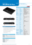
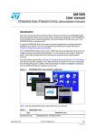
OptoFidelity Video Multimeter User Manual Version 2013Q2.0 OptoFidelity Oy • [email protected] • www.optofidelity.com OptoFidelity Video Multimeter – User Manual Contents 1 General information on OptoFidelity Video Multimeter ..................................... 3 2 Start window.............................................................................................. 3 3 Framerate measurement task ...................................................................... 4 3.1 Overview tab ....................................................................................... 4 3.2 Statistics tab ....................................................................................... 6 3.3 Configuration tab ................................................................................. 6 3.4 Color calibration................................................................................... 7 3.5 Saved data files ................................................................................... 7 4 USB connection .......................................................................................... 8 5 Software update ......................................................................................... 9 6 Technical specifications ..............................................................................10 7 Change history ..........................................................................................11 Page 2 of 11 OptoFidelity Video Multimeter – User Manual 1 General information on OptoFidelity Video Multimeter OptoFidelity Video Multimeter is a compact desktop solution for measuring the true and objective video playback performance of mobile, tablet or any multimedia device directly from the display. It is controlled with a touch display. This resistive touch display works best with e.g. a finger nail or a pen. 2 Start window When power is switched on, the device starts and Start Window opens up. All installed applications are listed in this window. List can be browsed by dragging or with the arrow buttons on the right. Figure 1: Start window after turning on the device. Applications are classified according to their purpose: Measurement tasks: Measurement applications, which are used to determine some feature of the device under test (DUT). Utilities: General utility programs for using and configuring Video Multimeter. Page 3 of 11 OptoFidelity Video Multimeter – User Manual 3 Framerate measurement task The framerate measurement task determines the playback smoothness of the DUT with a test video. A blinking marker is measured from the display of device, and this marker helps to determine frame intervals and missing frames. The basic measurement setup is shown in figure 2. Figure 2: Example of using Video Multimeter for frame rate measurement. 3.1 Overview tab When the frame rate measurement application is started, it opens to the overview tab shown in figure 3. On this tab, you can start and stop measurements, have an overview of the results and save them. The overview tab shows the average FPS over the whole measurement and the total number of frames. Figure 3: View of the application before measurement. Page 4 of 11 OptoFidelity Video Multimeter – User Manual To begin a new measurement, press the start button. The measurement will start immediately and continue until you press the stop button. While the measurement is ongoing, the graph will scroll to show the results, as shown in figure 4. Figure 4: Frame rate measurement in progress. The vertical axis of the graph indicates the time that each frame is on the screen. Readings on vertical axis are in milliseconds, so for example frame interval of 40 milliseconds equals to frame rate 1/0.040 = 25 FPS. Dropped frames are shown as red vertical bars if they occur. Note: To get repeatable results, start and stop the measurement in the white period at the start and end of the video. Such videos can be generated in OptoFidelity TVG by using setting calibration=both. After stopping the measurement, the results can be studied on the Stats tab, or saved using the Save button. After saving the results a message window shows the name of the saved file, like in figure 5. Figure 5: Message window after saving the measurement results. Page 5 of 11 OptoFidelity Video Multimeter – User Manual 3.2 Statistics tab During or after performing a measurement, you can switch to the statistics tab to see further information. The view is shown in figure 6. Figure 6: Statistics tab The upper row displays the minimum, average, standard deviation and maximum values of the frame intervals. Lower row displays the total number of frames and the amount of dropped frames. 3.3 Configuration tab By default the application uses RGB marker with built-in color calibration. This is suitable for most measurement situations with LCD displays. For other kinds of displays, adjustments on the Config tab may be necessary. Figure 7: Configuration tab Page 6 of 11 OptoFidelity Video Multimeter – User Manual As shown in figure 7, the configuration tab allows selection of marker type and color calibration. The available marker types are: 1. RGB (6-color): Marker with specific color sequence of 6 different colors. This measures frame intervals and detects dropped frames. 2. Black & White: Black and white marker. Simple method for testing frame intervals, but detecting dropped frames is not possible. 3. Any change: Any large change of color will be considered as a change of frame. Can measure frame intervals of any marker, but dropped frames will not be detected. The selected marker type must match the type of the marker in the test video used. 3.4 Color calibration The functionality of RGB marker depends on the color space of the DUT, since RGB marker is based on colors. Default settings can be applied for most LCD displays, but OLED displays and other display technologies may require calibration. You can easily see that calibration is needed, if red bars turn up on the graph constantly. This indicates that some colors have not been detected. Calibration is performed as follows: 1. Position fiber on a color marker on display. The video must be running. 2. Press Calibrate button on the Config tab. Calibration takes few seconds and fiber must be kept still on the marker during this time. 3. New calibration is valid immediately. If required, you can do calibration again or deactivate calibration by pressing the No calibration button. Note: Color calibration is only necessary for the RGB marker. It is not necessary and cannot be successfully performed for other kinds of markers. 3.5 Saved data files The saved data files from frame rate measurement are in semicolon separated CSV format. Each row corresponds to one frame, and has the following columns: 1. 2. 3. 4. Microsecond timestamp of the frame start. Microsecond length of the frame (-1 for dropped frames). Color of the marker in the frame. Cumulative count of frames dropped since start of measurement. Page 7 of 11 OptoFidelity Video Multimeter – User Manual Figure 8: Data file saved from frame rate measurement. The CSV format is supported by e.g. Microsoft Excel and many other data analysis tools. 4 USB connection Video Multimeter can be connected to computer by a USB cable for battery charging and data transfer. Charging will begin as soon as the USB cable is connected and is indicated by a red LED next to the USB connector. When the battery is full, the LED will turn off. Note that if the device is on, the LED will not turn off because power is being used. Figure 9: USB mode selection screen. When the USB cable is connected and the device is on, a selection window such as in figure 9 opens up on the display. The window has options Data transfer and Charge only. If Data transfer is selected, the device will appear as an USB memory on the computer. Other functions of the device will not be available while the data transfer is active. Selecting Charge only will simply close the dialog so that the device can be used normally while it is being charged. Page 8 of 11 OptoFidelity Video Multimeter – User Manual 5 Software update Connect the device with USB cable to the computer to update the software. Switch the power on while holding down the button next to power switch by e.g. a pen. Device should become visible as a USB DFU device, and drivers should be installed automatically. Start Firmware upgrade application by computer, and click Start button. Application informs when the software upgrade is done. Finally detach the device from computer and switch it off to exit the upgrade mode. If software update is interrupted for some reason, you can run the upgrade again as described above. Upgrade mode is separate from the main software, so damaged software does not prevent upgrading. Note: When the device is started in the firmware upgrade mode, the screen will display random noise. Reboot the device to exit the upgrade mode. Figure 10: Firmware upgrade application. Page 9 of 11 OptoFidelity Video Multimeter – User Manual 6 Technical specifications External dimensions: 12x8x3 cm Operating temperature range: -10 C to +40 C Storage temperature range: -20 C to +60 C Internal memory: 4 GB Operating time on battery: 6 hours Battery: Li-Ion Panasonic PA-L2, 1950 mAh, 7 Wh Operating current: 300 mA Built-in fiber sensor bandwidth 4 kHz Built-in fiber sensor sample rate 100 kS/s Synchronization output voltage (low) 0.0 V to 0.4 V Synchronization output voltage (high) 2.9 V to 3.3 V Synchronization output impedance 50 ohm Page 10 of 11 OptoFidelity Video Multimeter – User Manual 7 Change history Ver. 1.0 1.1 1.2 Status Draft Release Release Date 5.3.2013 7.5.2013 27.5.2013 Author KRY JPA JPA Remarks First release Release 2013Q1.0 FPS UI + file format Page 11 of 11