1
Camera Phone Flash Evaluation Board User’s Manual
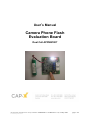
Board Features
FLASH mode with adjustable voltage and current
TORCH/MOVIE/GPRS mode with adjustable voltage and current
VOUT/GND connector to evaluate GPRS Power Amplifier
On-board or External triggering
On-board or External white LEDs
LED and inductor current measurement ability
Auto run for flash or torch
Quick Setup
The following jumpers should be in place J1, J4, J5, J8, J9, J10, J12 and J15. Connect the
positive terminal of a single cell Lithium Ion rechargeable battery (3.3V-4.2V) to any pin on J2
and connect the negative terminal to any pin of J3. The red LED (D2) should come on
immediately.
TORCH
Flick the toggle switch (SW2) to the left (towards the TORCH pushbutton SW1). Pressing
SW1 will now cause 100mA (factory set) to flow through each of the white LEDs (D5 & D6).
With the factory setting of 100mA per white LED, SW1 can be held down continuously.
FLASH
Flick the toggle switch (SW2) to the right (towards the FLASH pushbutton SW3). Pressing
SW3 will now cause 1A (factory set) to flow through each of the white LEDs (D5 & D6) for
approximately 80ms. If the button is held down continuously the flash will retrigger
approximately every 2.5s. This duty cycle is imposed due to the thermal constraints of the
white LED.
GPRS
GPRS mode is the same as TORCH mode, ie flick the toggle switch (SW2) to the left
(towards the TORCH pushbutton SW1). The factory set output voltage is 3.8V and it is
available on the orange connector (TB1) to be connected to a Power Amplifier or other
pulsed load.
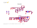
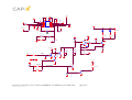
Circuit Description (refer to schematics at the end of this manual)
Input Voltage
The circuit is designed to operate from an external Li ion battery (4.2V-3.3V).
Vbat is the node connected to the battery via J2.
J2 is to be connected to battery positive terminal. Pins 1 and 2 of J2 are joined.
J3 is to be connected to battery negative terminal. Pins 1 and 2 of J3 are joined.
A current limiting MOSFET (M1) is not currently installed on the PCB and as such the bypass
jumper (J15) needs to be installed.
Indicating LED
D2 is a red LED that indicates a source voltage is present.
Buck/Boost Converter
J1 needs to be jumpered for normal operation. This jumper has been included so a wire loop
can easily be inserted to measure the inductor current. By measuring the inductor current
and monitoring the voltage of pin 6 of U1 the average output current can also be determined.
All information contained herein is strictly confidential
© CAP-XX Pty Limited 2005
APPEB1007 User Manual rev1.0, 31-May-2005
page 2 of 6