1
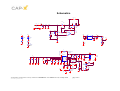
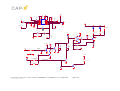
The controller is an LTC3442 from Linear Technology. Its “Soft Start” and “Burst” features are
not currently utilized and as such J4 and J5 need to be jumpered to disable these features.
Inrush Current
A discharged supercapacitor presents itself as a short circuit and therefore inrush current
needs to be managed. The LTC3442 has an average input current limiting feature and this
has been set to approximately 1.5Amps by selecting R11 = 47KΩ.
FLASH MODE
For FLASH mode, Vout is factory set to 4.5V. This voltage can be reduced by turning R21 (a
100k pot) anticlockwise.
TORCH MODE
The continuous current required for TORCH is << FLASH current (typically 200mA Vs 2A).
Therefore the voltage dropped across the white LEDs will be less. To increase efficiency
(and to reduce thermal stress on the current limiting MOSFET (M4)) Vout should also be
reduced. Vout can be adjusted using R22 (a 1M pot). Vout is factory set to 3.8V. The FLASH
mode voltage needs to be adjusted prior to the TORCH mode voltage because the FLASH
setting affects the TORCH setting but not vice versa. If Jumper J12 is removed then the
TORCH / GPRS mode voltage is the same as that set in Flash Mode above and R22 has no
effect.
GPRS MODE
GPRS mode is the same as TORCH mode (factory set to 3.8V). The Vout setting (adjusted
using R22) has to satisfy both the external Power Amplifer and have enough voltage
headroom to drive the white LEDs in TORCH mode for the TORCH Mode current selected.
Current Control
FLASH MODE
The FLASH current is factory set to 2.0 Amps (shared between two white LEDs). It can be
reduced by turning R33 (10k pot) anti-clockwise. The current in a single white LED should
not exceed 1 Amp so if only one LED is to be used then the FLASH current should be
reduced to 1 Amp or less prior to driving the single LED. The FLASH current needs to be
adjusted prior to the TORCH current because the FLASH setting affects the TORCH setting
but not vice versa.
TORCH MODE
The TORCH current is factory set at 200mA. It can be reduced by turning R34 (2k pot) anticlockwise or increased by turning R34 clockwise. Care should be taken not to increase Torch
mode current > 400mA total (200mA per LED) so as not to overheat and destroy the LEDs.
GPRS MODE
The maximum average load current is determined by the average input current limit which is
set at 1.5Amps on the LTC3442 Buck/Boost controller. Assuming 85% efficiency, maximum
average load current = 1.5A x Vbat/(Vout in TORCH mode) x 85%. Providing the DC:DC
converter provides sufficient average load current, the supercapacitor will provide the peak
currents.
All information contained herein is strictly confidential
© CAP-XX Pty Limited 2005
APPEB1007 User Manual rev1.0, 31-May-2005
page 3 of 6