1
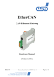
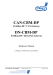
CAN-PC104/331
PC/104-CAN-Interface
Hardware Installation
and
Technical Data
Installation and technical data CAN-PC104/331 Rev. 1.5
Document file:
I:\texte\Doku\MANUALS\CAN\PC104331\PC1015H.en9
Date of print:
25.02.2002
PCB version:
CAN-PC104 Rev. 1.0
Changes in the Chapters
The changes in the user’s manual listed below affect changes in the hardware, as well as changes
in the description of the facts only.
Chapter
Alterations with respect to previous version
1.3
New chapter ‘Connector Position and Board Dimensions’.
5.
New chapter ‘Version CAN-PC104/xxx-Micromatch’
Further technical changes are subject to change without notice.
Installation and technical data CAN-PC104/331 Rev. 1.5
NOTE
The information in this document has been carefully checked and is believed to be entirely reliable.
esd makes no warranty of any kind with regard to the material in this document, and assumes no
responsibility for any errors that may appear in this document. esd reserves the right to make
changes without notice to this, or any of its products, to improve reliability, performance or
design.
esd assumes no responsibility for the use of any circuitry other than circuitry which is part of a
product of esd gmbh.
esd does not convey to the purchaser of the product described herein any license under the patent
rights of esd gmbh nor the rights of others.
esd electronic system design gmbh
Vahrenwalder Str. 207
30165 Hannover
Germany
Phone:
Fax:
E-mail:
Internet:
+49-511-372 98-0
+49-511-372 98-68
[email protected]
www.esd-electronics.com
USA / Canada
7667 W. Sample Road
Suite 127
Coral Springs, FL 33065
USA
Phone:
Fax:
E-mail:
+1-800-504-9856
+1-800-288-8235
[email protected]
Installation and technical data CAN-PC104/331 Rev. 1.5
Contents
1. Overview . . . . . . . . . . . . . . . . . . . . . . . . . . . . . . . . . . . . . . . . . . . . . . . . . . . . . . . . . . . .
1.1 Module Description . . . . . . . . . . . . . . . . . . . . . . . . . . . . . . . . . . . . . . . . . . . . . . . . . .
1.2 PCB View With Connector Designation . . . . . . . . . . . . . . . . . . . . . . . . . . . . . . . . . .
1.3 Connector Position and Board Dimensions . . . . . . . . . . . . . . . . . . . . . . . . . . . . . . . .
3
3
4
5
2. Hardware Installation . . . . . . . . . . . . . . . . . . . . . . . . . . . . . . . . . . . . . . . . . . . . . . . . . . 6
2.1 Before Starting Hardware Installation . . . . . . . . . . . . . . . . . . . . . . . . . . . . . . . . . . . . 6
2.2 Execute Hardware Installation and Setting of PC/104-Bus Address . . . . . . . . . . . . . . 7
3. Summary of Technical Data . . . . . . . . . . . . . . . . . . . . . . . . . . . . . . . . . . . . . . . . . . . .
3.1 General Technical Data . . . . . . . . . . . . . . . . . . . . . . . . . . . . . . . . . . . . . . . . . . . . . .
3.2 PC/104 Bus . . . . . . . . . . . . . . . . . . . . . . . . . . . . . . . . . . . . . . . . . . . . . . . . . . . . . . .
3.3 CAN Interface . . . . . . . . . . . . . . . . . . . . . . . . . . . . . . . . . . . . . . . . . . . . . . . . . . . . .
3.4 Software Support . . . . . . . . . . . . . . . . . . . . . . . . . . . . . . . . . . . . . . . . . . . . . . . . . .
3.5 Order Information . . . . . . . . . . . . . . . . . . . . . . . . . . . . . . . . . . . . . . . . . . . . . . . . . .
10
10
10
11
11
12
4. Connector Assignment . . . . . . . . . . . . . . . . . . . . . . . . . . . . . . . . . . . . . . . . . . . . . . . .
4.1 CAN Interfaces (X400, X401) . . . . . . . . . . . . . . . . . . . . . . . . . . . . . . . . . . . . . . . . .
4.2 CAN-TTL Signals (X402) . . . . . . . . . . . . . . . . . . . . . . . . . . . . . . . . . . . . . . . . . . . .
4.3 Option: DeviceNet Adapter Boards . . . . . . . . . . . . . . . . . . . . . . . . . . . . . . . . . . . . .
13
13
14
15
5. Version CAN-PC104/xxx-Micromatch . . . . . . . . . . . . . . . . . . . . . . . . . . . . . . . . . . . .
5.1 Overview . . . . . . . . . . . . . . . . . . . . . . . . . . . . . . . . . . . . . . . . . . . . . . . . . . . . . . . . .
5.2 Pin Assignment Micromatch Socket . . . . . . . . . . . . . . . . . . . . . . . . . . . . . . . . . . . . .
5.3 Adapter Cable Micromatch (male) to DSUB9(male) . . . . . . . . . . . . . . . . . . . . . . . .
18
18
19
20
6. Correctly Wiring Electrically Insulated CAN Networks . . . . . . . . . . . . . . . . . . . . . . 21
Installation and technical data CAN-PC104/331 Rev. 1.5
1
This page is intentionally left blank.
2
Installation and technical data CAN-PC104/331 Rev. 1.5
Overview
1. Overview
1.1 Module Description
C
A
N
B
U
S
electrical isolation
Physical
CAN
Layer
DSUB9
CiA pinning
CAN
CAN Controller
SJA1000
SRAM
Microcontroller
68331
Arbiter
+5 V=
DC/DC
Converter
2. CAN Interface
only at
CAN-PC104/331-2
+5 V=
10-pole
Connector
Plugs
C
A
N
B
U
S
electrical isolation
Physical
CAN
Layer
DSUB9
CiA pinning
CAN
CAN Controller
SJA1000
Flash EPROM
FIFO
512 bytes
FIFO
512 bytes Rx Data
Tx Data
IRQ
+5 V=
DC/DC
Converter
+5 V=
PC/104 Connector
Fig. 1.1.1: Block-circuit diagram of the CAN-PC104 module
The CAN-PC104 board is a CAN module designed for the PC/104-bus (PC/104 16 bits). It uses
a 68331 microcontroller, which cares for the local management. The CAN data is buffered in a
local SRAM. Security and consistency of data is guaranteed up to 1 Mbit/s.
The ISO 11898 compliant CAN interface allows a data-transfer rate of a maximum of 1 Mbit/s.
Among many other features, the bit rate can be set by software.
The CAN interface is electrically separated from other voltage potentials by means of optocouplers
and DC/DC converters.
Installation and technical data CAN-PC104/331 Rev. 1.5
3
Overview
1.2 PCB View With Connector Designation
Fig. 1.2.1: Module view
4
Installation and technical data CAN-PC104/331 Rev. 1.5
Overview
1.3 Connector Position and Board Dimensions
96,0
86,0
55,0
51,0
31,0
10-pole
male connector
DSUB 9
All listed values are in millimetres.
Fig. 1.3.1: CAN-PC104/331 technical drawing
Installation and technical data CAN-PC104/331 Rev. 1.5
5
Installation
2. Hardware Installation
2.1 Before Starting Hardware Installation
During the hardware installation it may be necessary to change the PC/104-I/O-port address. The
default address is 1E0...1E7 HEX. The CAN module covers 8 data bytes. Furthermore it is
necessary to set the interrupt during the following software installation.
Make sure that there will be no address conflict with other boards of the PC/104-systems
and that there will be no conflict with other interrupts!
Windows NT/2000/XP Users:
In order to avoid address and interrupt conflicts, the used address ranges should be checked
before starting the hardware installation.
This can be done in Windows NT 4.0 e.g. by selecting Programs/Administrative Tools
(Common)/ Windows NT Diagnostics. In the dialogue box Windows NT Diagnostics call
Resources and there select I/O Port. A list with the used and available address ranges appears.
Make sure that the default value of the PC104/331 is in a free memory area. If it is not, note
one free memory area (which corresponds to the choices stated in fig. 2.2.2) and change the
PC104/331 address by means of the coding switch during the hardware installation described
below.
In the same dialogue box call Interrupts. A list with the used interrupt lines appears. Note a free
interrupt, because you have to select an interrupt for the CAN module during the software
installation. (The complete software installation sequence is described in the software manual
‘CAN API with Software Tools and Installation Notes’.)
Windows 9x/ME Users:
If you use a Windows 9x/ME operating system first read the software installation guide in
the appendix of the manual ‘CAN API with Software Tools and Installation Notes’ and then
start with the installation sequence!
6
Installation and technical data CAN-PC104/331 Rev. 1.5
Installation
2.2 Execute Hardware Installation and Setting of PC/104-Bus Address
The CAN-PC104 module can be used in all PC/104-compatible 16-bit systems (e.g. portable
industry PCs or installed control systems). The carrier system will therefore be described by the
general term ‘computer’ below.
Attention !
Electro static discharge may cause damage to electronic devices. To avoid this, first do the
following steps to discharge your personal static electricity, before you touch the CAN module:
@ Switch off the power supply of all units but leave the connector plug in the socket.
@ Then touch the computer’s metal case to discharge the static electricity.
@ Even your clothes must not touch the CAN module!
1. Switch off the computer and all connected peripheral devices (monitor, printer, ...). Switch off
the CAN devices of the net to that the CAN module is to be connected.
2. Discharge yourself as described above if not yet done.
3. Disconnect the computer from mains by removing the mains connector.
If the computer does not have a flexible mains lead but is fixed to the mains, disconnect the
supply voltage via the safety fuse and protect the fuse from switching on again unintentionally.
4. Remove the computer cover
5. Select a free position in the PC/104-bus stack.
There are no restrictions in choosing a position in the stack for this module as long as there
are only 16-bit modules between it and the CPU.
6. Have you made sure that there will be no address conflict with other PC/104 boards? (See
chapter '2.2.1 Before Starting Hardware Installation' above.)
If you have to change the address of the board, go on with step 7 otherwise go on with step
8.
7. Setting the PC/104-bus-I/O-port address
The address is set via the coding switch S100. Its position can be taken from figure 1.2.1 on
page 4.
If a coding switch is set to ‘OFF’, the according address is evaluated as ‘1'. If it set to ‘ON’,
the according address is evaluated as ‘0'.
Installation and technical data CAN-PC104/331 Rev. 1.5
7
Installation
1
Coding switch:
PC/104-port address:
2
3
4
5
6
7
8
”
”
”
”
”
”
”
”
A9
A8
A7
A6
A5
A4
A3
--
ON
•
–
OFF
Fig. 2.2.1: Coding switch S100
The hardware address has to be given to the driver during the software installation. The menu
of the installation program offers a choice of the following addresses:
0x100 - 0x107 HEX
0x1E8 - 0x1EF HEX
1 2 3 4 5 6 7 8
1 2 3 4 5 6 7 8
0x2A0 - 0x2A7 HEX
1 2 3 4 5 6 7
OFF
OFF
OFF
0x1E0 - 0x1E7 HEX
0x250 - 0x257 HEX
1 2 3 4 5 6 7 8
1 2 3 4 5 6 7 8
1 2 3 4 5 6 7
OFF
OFF
OFF
Default setting
Coding switch = 'ON'
(address bit = 0)
0x3F0 - 0x3F7 HEX
8
1 2 3 4 5 6 7 8
OFF
0x390 - 0x397 HEX
8
Coding switch = 'OFF'
(address bit = 1)
Coding switch is
not evaluated
Fig. 2.2.2: Default setting of coding switches
and choices of addresses supported by installation program
The installation program does not support any other coding switch positions.
If you use a Windows 9x/ME operating system, you have to set the coding switches as
proposed by the Windows-Hardware Wizard.
@@
8
Installation and technical data CAN-PC104/331 Rev. 1.5
Installation
8. Install the CAN module at the selected PC/104-stack position.
9. Close the computer case.
10. Connect the CAN or DeviceNet.
Please note that the CAN has to be terminated at both ends. esd offers special T-connectors
and terminators. Furthermore the CAN-GND signal has to be earthed at exactly one point in
the CAN net. Therefore the termination connectors are equipped with an earth connector. A
CAN participant without an electrically separated interface acts as an earth connection.
Please consult the notes on correct wiring of CAN nets in the last chapter of this
manual!
The first CAN interface (CAN net 0) is connected via the DSUB-connector (X400) and the
second interface (CAN net 1) is connected via the DSUB-connector (X401).
11. Connect the power supply of the computer (mains connector or fuse).
12. Switch on the power supply of the computer, the peripheral devices and the other CAN
participants.
13. End of hardware installation.
The software installation is described in the manual ‘CAN-API with Software Tools and
Installation Notes’.
Installation and technical data CAN-PC104/331 Rev. 1.5
9
Technical Data
3. Summary of Technical Data
3.1 General Technical Data
Ambient temperature
0...50 /C
Humidity
max. 90%, non-condensing
Supply voltage
via PC/104-bus,
nominal voltage: 5 V ±5%,
current (typ., at 20 /C): 0.55 A (1x CAN)
0.70 A (2x CAN)
Plug-and-socket
connectors
X100 (64-pole PC/104 PCB connector) - PC/104 bus
X101 (40-pole PC/104 PCB connector) - PC/104 bus
X400 (DSUB9/male) - CAN interface 1 (net 0)
X401 (DSUB9/male) - optional CAN interface 2 (net 1)
X402 (10-pole male connector) - CAN-TTL signals for
CAN/DeviceNet adapter board
The following connectors are only equipped for programming and
service:
X200 (4-pole female con.
- CPU interface (serial, TTL)
X201 (10-pole male connector) - BDM interface
X501 (5-pole male con.)
- ISP programming
Dimensions
95.9 mm x 90.2 mm
Weight
1x CAN: 85 g
2x CAN: 95 g
Table 3.1.1: General module data
3.2 PC/104 Bus
Host bus
PC/104
PC/104-data bus
16 bit
Interface
IN/OUT-FIFOs (512 bytes each)
Interrupt
1 out of 12
Stack position
no restrictions in position in stack
Connectors
PC/104 PCB connectors, 40-pole and 64-pole
Table 3.2.1: PC/104-bus data
10
Installation and technical data CAN-PC104/331 Rev. 1.5
Technical Data
3.3 CAN Interface
Number
1,
optionally 2 CAN interfaces
CAN controller
SJA1000
CAN protocol
basic-CAN 2.0A/B
Physical interface
ISO 11898 compliant physical layer, transfer rate
programmable from 10 kbit/s to 1 Mbit/s
Bus termination
has to be set externally
Electrical separation of CAN
interfaces from other units
separation of CAN interfaces from each other and from
PC/104-bus potentials by optocouplers and DC/DC
converters
DeviceNet Option
adapter board with Phoenix Combicon style connector,
optocouplers and CAN driver acc. to DeviceNet
specification ‘DeviceNet Communication Model and
Protocol, Rel. 2.0’
Table 3.3.1: CAN-interface data
3.4 Software Support
The product package contains software examples for DOS and Windows 3.11. Furthermore
software drivers for Windows NT/2000/XP and Windows 9x/ME are available. The Windows NT
driver is written in kernel mode and multiprocessor-conform. The Windows 9x/ME driver is
realized as VxD. The firmware can be loaded from the PC into the flash EPROM.
Software packages for CANopen or DeviceNet are available.
Installation and technical data CAN-PC104/331 Rev. 1.5
11
Technical Data
3.5 Order Information
Type
Properties
Order no.
CAN-PC104/331-1
1xCAN
C.2012.02
CAN-PC104/331-2
2xCAN
C.2012.04
CAN-PC104/331-2 MM
2x CAN with Micromatch connector instead
of DSUB9 for CAN
C.2012.09
CAN-PC104/331-DvN
DeviceNet-Adapter
C.2012.25
CAN-PC104/331-95
Windows 95 VxD driver
C.2012.10
CAN-PC104/331-NT
Windows NT Device driver
C.2012.11
CAN-PC104/331-QNX
QNX4 driver
C.2012.32
CAN-PC104/331-Co
CANopen master/slave-Object Licence
C.2012.12
CAN-PC104/331-DvN
DeviceNet-object licence
C.2012.13
CAN-PC104/331-ME *)
English hardware manual for C.2012.02 ...
C.2012.09
C.2012.21
CAN-API-ME *)
English software manual for C.2012.10,
C.2012.11 and C.2012.32
C.2001.21
CAL/CANopen-ME *)
Additional software manual for C.2012.12
C.2002.21
Options:
*) If order together with the module, the manual will be delivered free of charge.
Table 3.5.1: Order information
12
Installation and technical data CAN-PC104/331 Rev. 1.5
Connector Assignment
4. Connector Assignment
4.1 CAN Interfaces (X400, X401)
The assignment of the signals to the connector pins of the first CAN interface (X400) is equal to
the assignment of the optional second CAN interface X401. Both connectors are 9-pole DSUBs
with male contacts.
Pin Location:
Pin Assignment:
Signal
Pin
CAN_GND
6
CAN_H
7
reserved
8
reserved
9
Signal
1
reserved
2
CAN_L
3
CAN_GND
4
reserved
5
shield
9-pole DSUB male
Signal Description:
CAN_L, CAN_H...
CAN-signal lines
CAN_GND ...
reference potential of the local CAN-physical layer
Shield ...
potential of the connector cover
reserved ...
reserved for future applications
Installation and technical data CAN-PC104/331 Rev. 1.5
13
Connector Assignment
4.2 CAN-TTL Signals (X402)
Connector X402 carries the Rx/Tx-signals of the CAN controller. The signals are on TTL level
and are not electrically separated from the microcontroller units!
Signal name
14
Pin
Signal name
+5V
1
2
Tx00*
Tx01*
3
4
Rx00*
Rx01*
5
6
Tx10*
Tx11*
7
8
Rx10*
Rx11*
9
10
GND
Installation and technical data CAN-PC104/331 Rev. 1.5
Connector Assignment
4.3 Option: DeviceNet Adapter Boards
The two CAN channels can be wired to two adapter boards via X402. Each adapter board offers
one DSUB9 or one DeviceNet connector. The adapter boards are designed for fixing at the case
panel. The pinning of the DSUB connectors is as described in chapter ‘CAN-Interfaces (X400,
X401).
The DeviceNet interface is designed according to the specification ‘DeviceNet Communication
Model and Protocol, Release. 2.0’. The power supply of the CAN bus driver has to be supported
from external and the wiring is done by Phoenix Combicon style connectors MSTB 2.5/-GF-5.08
(or equivalent).
Pin Assignment:
1
2
3
4
5
Pin
Signal
1
V-
2
CAN-
3
shield
4
CAN+
5
V+
Signal Description:
V+...
power supply for CAN interface (UVCC = 24 V ± 4%)
V-...
reference GND for V+ and CAN+/CAN-
CAN+, CAN-...
CAN signals
Shield...
shielding
(via high resistance RC-combination connected to earth (shield panel))
Installation and technical data CAN-PC104/331 Rev. 1.5
15
Connector Assignment
The DeviceNet option includes the CAN-PC104/331-board, the DeviceNet adapter board, the
ribbon cable, the fixing brackets and all necessary bolds, screws and washers.
Case Panel
CAN/DeviceNet
Adapter 2
CAN Net 1
OUT
CAN/DeviceNet
Adapter 1
CAN Net 0
IN
OUT
PC/104-Stag
Fixing
Brackets
IN
X402
DSUB9 or
DeviceNet
Connector
Ribbon Cable
CAN-PC104/331-Board
Fig. 4.3.1: Wiring of the adapter boards
All dimensions given in the following drawings are in millimeters.
36,0
27,8
20,5
25,3
o 3.8
10,7
11,4
10,3
9,0
7,3
o 3.2
8,2
25,0
42,55
Fig. 4.3.2: Recess in case panel for adapter
boards with DeviceNet connector
16
Fig. 4.3.3: Recess in case panel for adapter
boards with DSUB9-connector
Installation and technical data CAN-PC104/331 Rev. 1.5
20,0
15,0
Connector Assignment
5,0
15,0
5,0
40,0
Fig. 4.3.4: Required free space outside the
case for adapter boards with
DeviceNet connector (space
Fig. 4.3.5: Required free space outside the
case for adapters boards with
DSUB9-connector
considers e.g. the following Phoenix
combicon-style connector types:
MSTB, MSTBP, MVSTBR, MVSTBW,
TMSTBP)
max. 4,0
27,0
27,0
4,0
15,0
56,0
Fig. 4.3.6: Required free space inside the case
for adapter boards with DeviceNet or
DSUB9-connector
Installation and technical data CAN-PC104/331 Rev. 1.5
17
Connector Assignment
5. Version CAN-PC104/xxx-Micromatch
5.1 Overview
This version of the PC104-module has got an AMP-Micromatch socket instead of a DSUB9CAN-connector. The socket is so small that it does not protrude the PCB, even if it is
connected to a plug. This is of great advantage, if the module is to be used in a narrow case.
esd offers the adapter cable ‘CAN-Cable-MB’ (Order No. C.1323.015) with a length of 15 cm
to convert from micromatch connector to DSUB9. The DSUB-connector of the adapter cable
corresponds to the standard assignment of a 9-pin DSUB-connector for CAN (see DSUB9CAN-connectors). The adapter cable has to be ordered in addition to the PC104-module.
Attention: The micromatch connector is not protected against wrong polarity!!
The connecting cable must always be connected as shown in the figure below!
If you want to make the adapter cable yourself, you require the following information:
The AMP-socket used on the board has got the following designation:
AMP Micromatch, FL, 10-pin, No. 8-215079-0
18
Installation and technical data CAN-PC104/331 Rev. 1.5
Connector Assignment
The plug required, designed for use with standard flat-ribbon cables and crimp connection, has
got the following designation:
AMP Micromatch, FRC, 10-pin, No. 8-215083-0
(available, e.g. from Farnell under order number 149-081)
The maximum length of the adapter cable including the externally connected cable to
the T-piece must not exceed 30 cm (ISO11898)!
5.2 Pin Assignment Micromatch Socket
The following table shows the assignment of the micromatch socket on the board. Pin 6 of the
socket is not assigned.
Pin Assignment (View from Top Layer onto Connector):
Signal
Pin
reserved
1
CAN_L
2
CAN_GND
3
reserved
4
Signal
6
not connected
7
CAN_GND
8
CAN_H
9
reserved
10
reserved
shield
5
10-pin AMD-micromatch socket
Installation and technical data CAN-PC104/331 Rev. 1.5
19
Connector Assignment
5.3 Adapter Cable Micromatch (male) to DSUB9(male)
The adapter cable ‘CAN-Cable-MB’ (Order No. C.1323.015) consists of the two connectors
and one flat-ribbon cable with 9 wires which is crimped with wire 1 to pin 1 of the DSUBconnector at one end and with wire 1 to pin 1 of the micromatch connector at the other end.
The highest pin of the micromatch connector (pin 6) is not assigned.
DSUB9-connector
(male) Pin
1
2
3
4
5
Flat-ribbon cable
signal
reserved
CAN_L
CAN_GND
reserved
shield
Micromatch
connector
(male) Pin
1
2
3
4
5
6
6
7
8
9
20
CAN_GND
CAN_H
reserved
reserved
7
8
9
10
Installation and technical data CAN-PC104/331 Rev. 1.5
Wiring
6. Correctly Wiring Electrically Insulated CAN Networks
Generally all instructions applying for wiring regarding an electromagnetic compatible
installation, wiring, cross sections of wires, material to be used, minimum distances, lightning
protection, etc. have to be followed.
The following general rules for the CAN wiring must be followed:
1.
A CAN net must not branch (exception: short dead-end feeders) and has to be
terminated by the wave impedance of the wire (generally 120 Ω ±10%) at both ends
(between the signals CAN_L and CAN_H and not at GND)!
2.
A CAN data wire requires two twisted wires and a wire to conduct the reference
potential (CAN_GND)!
For this the shield of the wire should be used!
3.
The reference potential CAN_GND has to be connected to the earth potential (PE)
at one point. Exactly one connection to earth has to be established!
4.
The bit rate has to be adapted to the wire length.
5.
Dead-end feeders have to kept as short as possible (l < 0.3 m)!
6.
When using double shielded wires the external shield has to be connected to the
earth potential (PE) at one point. There must be not more than one connection to
earth.
7.
A suitable type of wire (wave impedance ca. 120 Ω ±10%) has to be used and the
voltage loss in the wire has to be considered!
8.
CAN wires should not be laid directly next to disturbing sources. If this cannot be
avoided, double shielded wires are preferable.
Wire structure
Signal assignment of wire and connection of earthing and terminator
CAN wire with connectors
DSUB9 connector
(female or male)
pin designation
CAN_L
CAN_GND
120 Ohm
CAN_H
1
2
3
4
5
6
7
8
9
connector case
DSUB9 connector
(female or male)
pin designation
CAN_GND
(at wire shield)
n.c.
CAN_L
n.c.
n.c.
n.c.
n.c.
n.c.
n.c.
CAN_H
n.c.
n.c.
n.c.
n.c.
n.c.
n.c.
n.c.
n.c. = not connected
1
2
3
4
5
6
7
8
9
connector case
120 Ohm
Shielded wire with
transposed wires
earth (PE)
Figure: Structure and connection of wire
Installation and technical data CAN-PC104/331 Rev. 1.5
21
Wiring
Cabling
• for devices which have only one CAN connector use T-connector and dead-end feeder
(shorter than 0.3 m) (available as accessory)
CAN
Board
e.g. PCI/331,
ISA/331,
VME-CAN2, etc.
Net 1
Connecting
CAN_GND to
Protective Conductor PE
PE
Terminator
with PE Connector
CAN_H
Female Connector
CAN_L
Male Connector
CAN_GND
Male Terminator
Female Terminator
T-Connector
Net 2
l < 0,3 m
T-Connector
Terminator
l < 0,3 m
CAN
Module
CDIO16/16
CAN
Module
CMIO
CAN
Module
CAI810
CAN-SPS
Interface
CSC595/2
or
CAN-PC Board
CAN
Module
CDMS4
Figure: Example for correct wiring (when using single shielded wires)
Terminal Resistance
• use external terminator, because this CAN later be found again more easily!
• 9-pin DSUB terminator with male and female contacts and earth terminal are available as
accessories
Earthing
• CAN_GND has to be conducted in the CAN wire, because the individual esd modules are
electrically insulated from each other!
• CAN_GND has to be connected to the earth potential (PE) at exactly one point in the
net!
• each CAN user without electrically insulated interface works as an earthing, therefore: do
not connect more than one user without potential separation!
• Earthing CAN e.g. be made at a connector
22
Installation and technical data CAN-PC104/331 Rev. 1.5
Wiring
Wire Length
• Optical couplers are delaying the CAN signals. By using fast optical couplers and testing
each board at 1 Mbit/s, however, esd CAN guarantee a reachable length of 37 m at 1
Mbit/s for most esd CAN modules within a closed net without impedance disturbances like
e.g. longer dead-end feeders. (Exception: CAN-CBM-DIO8, -AI4 and AO4 (these
modules work only up to 10 m with 1 Mbit/s))
Bit rate
[kbit/s]
1000
800
666.6
500
333.3
250
166
125
100
66.6
50
33.3
20
12.5
10
Typical values of reachable
wire length with esd
interface lmax [m]
CiA recommendations
(07/95) for reachable wire
lengths lmin [m]
37
59
80
130
180
270
420
570
710
1000
1400
2000
3600
5400
7300
25
50
100
250
500
650
1000
2500
5000
Table: Reachable wire lengths depending on the bit rate when using esd-CAN interfaces
Examples for Suitable Types of Wire
Manufacturer
Type of wire
Manufacturer
Type of wire
U.I. LAPP GmbH & Co. KG
Schulze-Delitzsch-Straße 25
70565 Stuttgart
UNITRONIC ®-BUS LD,
UNITRONIC ®-BUS FD P LD
Alcatel Kabelmetal
Kabelkamp 20
30179 Hannover
DUE 4401, DUE 4001,
DUE 4402
metrofunk
KABEL-UNION GmbH
Postfach 410109
12111 Berlin
LiYCY 2 x 0,38 mm², LiYCY 2 x 0,5 mm²,
LiYCY 2 x 0,75 mm², LiYCY 2 x 1,0 mm²,
1P x AWG 22 C, 1P x AWG 20 C
ConCab Kabel GmbH
Äußerer Eichwald
74535 Mainhardt
1 x 2 x 0,22 mm²
Order no.: 93022016
(UL approved)
Installation and technical data CAN-PC104/331 Rev. 1.5
23