1
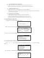
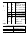
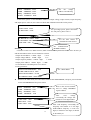
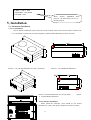
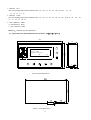
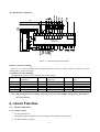
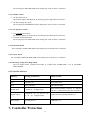
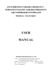
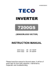
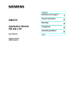
SCREW AIR COMPRESSOR CONTROLLER MAM-KY02SVF( B) -( VF-Ⅲ) (Monitor-200) USER MANUAL Shenzhen Plot Electronic Co., Ltd Address:4-5F,5 Bldg,Highstar Industry Park,Gangtou Community, Bantian,Longgang District,Shenzhen City,China Telephone:(+86 0755)83173599 / 83172822 Postal code:518034 Fax:(+86 0755)83172966 E-mail:[email protected] Web site:www.pltsz.com 1 VOTE OF THANKS Thank you for your trustworthy and select of PLOT air compressor controller ! Shenzhen Plot Electronic Co., Ltd specializes on the manufacture and R&D of air compressor controller. We are devoted to win customer trust through our high quality products and service. We try our best to ensure the completeness and correctness of the manual, but PLOT Company shall reserve the rights for continuous research and improvement on its products and assume no obligation for the modification and improvement on the previously delivered products. The design of products is subject to the change without notice. Please feel free to contact our after-sale service center if you encounter any problem with our product. You are always welcome to make suggestions and advices! 2 NOTICE Please read all the operation manual before operating the set and keep this manual for further reference. Installation of MAM—KY** compressor controller can be performed only by professional technicians. Installation position shall be considered carefully in order to ensure good ventilation and reduce electromagnetic interference. Wiring shall be performed respectively according to regulations for heavy and weak current to reduce electromagnetic interference. RC snubber must be connected to the two terminals of coil (such as AC contactor ,valve, etc),which are controlled by relay output. Port connection shall be inspected carefully before power on. Correct ground connection (the third ground)can help increase product capacity of resisting signal interference. Set rated current of motor: the max current of motor/1.2. Features: ● Chinese / English display. ● Integrate PID calculation and control , adjust load rate automatically based on air pressure and inverter operation frequency ● current open phase, current overload, current unbalance protection for motor ● On-off control and running control of motor. ● Prevention for air compressor reversal ● Temperature measurement , control and protection ● High integration , high reliability ,high cost performance. ● Remote control/Local control. ● Block mode/Independent mode. ● RS-485 communication function, one for inverter and the other for block control or external communication 3 Contents 1,Basic Operation..................................................................................................................................................... 5 1.1, Button Explanation................................................................................................................................... 5 1.2, Status Display and Operation .................................................................................................................. 6 2, Contoller Function and Technical Parameter ................................................................................................. 12 3,Model and Specification ..................................................................................................................................... 13 3.2, Power specification sheet for corresponding motor. ............................................................................ 13 4, Inverter Communication................................................................................................................................... 14 4.1,Communication Function..................................................................................................................... 14 4.2,Communication Set .............................................................................................................................. 14 4.3,Inverter Upgrade Explanation ....................................................................................................... 14 5, Installation.......................................................................................................................................................... 16 5.1, Mechanical Installation .......................................................................................................................... 16 5.2, Electrical Connections............................................................................................................................ 18 6, Alarm Function .................................................................................................................................................. 18 6. 1、Monitor Indication............................................................................................................................... 18 6.2,Controller indicator................................................................................................................................. 19 7, Controller Protection......................................................................................................................................... 19 8, Troubleshooting ................................................................................................................................................. 20 8.1、This Fault Review ................................................................................................................................. 20 8.2、Common Failures and Causes:............................................................................................................ 21 9, Schematic Diagram:........................................................................................................................................ 23 4 1,Basic Operation 1.1, Button Explanation Picture 1 I——Start Button: 1,When compressor is at stop status, press this button to start the compressor. 2,When compressor is set as master ( No.1 ) in block mode ,press this button to start the compressor and activate block mode function at the same time. O——Stop Button: 1,When the compressor is at running status, press this button to stop the compressor; 2,When compressor is set as master (No.1 ) in block mode ,press this button to stop compressor and block mode function as well. ——Load / unload Button: When the compressor is at running status ,press this button to load or unload ; S——Set Button: 1. When modifying data, press this button after modification to save and confirm the modified data. 2. When the compressor is at password setting status ,press this button to save and confirm the password ——Move up button/Increasing button: 1,when viewing the menu, press this button to move upward the cursor ; 2,When modifying data, press this button to increase the data at current position . 5 ——Move down button / Decreasing button: 1, When viewing the menu, press this button to move downward the cursor; 2,When modifying data, press this button to decrease the data at current position. ——Shift button /Enter button: 1,When modifying data, press this button to move to the next data bit; 2,when select menu, press this button to switch to submenu. If no submenu available, the controller will shift to data setting mode. C——Return button / Reset button: 1, When modifying data, press this button to exist data setting mode; 2, When viewing the menu, press this button to return to previous-menu; 3, When the controller is at failure stop status, long press this button to reset. 1.2, Status Display and Operation The display screen will show as below after power on:: WELCOME SCREW COMPRESSOR After 5 seconds, the menu will switch as below: DISC T:20℃ FREQ:50HZ AIR P:0.60Mpa SPEED:1234RPM LOADING FAN START FREQ:123.1KW VOLT:381V C01 Press “” to enter into Selection Menu: RUN PARAMETER CALENDAR CUSTOMER PARAMETER FACTORY PARAMETER 1.2.1, Operating Parameter and Menu Press“” or“” to move the cursor to “RUN PARAMETER”, then press“” to switch to secondary menu: MOTOR、FAN CURR VSD PARAMETER TOTAL RUN TIME THIS RUN TIME Move the cursor to “MOTOR,FAN CURR” ,press“” to switch to secondary menu: CURR(A):R S T 6 MOTOR: 56.1 56.2 56.0 FAN: 4.1 4.1 4.1 Press “RT”, to return to the previous menu or the main menu. If no operation at the current menu for 120 seconds , controller will automatically return to the main menu and turn off the back light simultaneously. According to above method, use move down “” ,move up button“”, enter button“”and return button “C” to check TOTAL RUN TIME,THIS RUN TIME,VSD PARAMETER,MAINTENANCE PARA,FAULT RECORD, PROD.DATE、SERIAL,THIS FAULT and return to previous menu. 1.2.2, Calendar Check and set time of controller TIME 2004-2-22 WEEK0 12:46:59 1.2.3, Customer Parameter A, Customer parameter view and modification It is not allowed to modify CUSTOMER PARAMETER and FACTORY PARAMETER in running status and STOP DELAY The check and modification of CUSTOMER PARAMETER is similar with RUN PARAMETER. Take UNLOAD P as example: Move “”or“”to CUSTOMER PARAMETER and then press “”to switch to below menu SET P、T、VSD PARAMETER SET TIME OPERATION MODE BLOCK PARAMETER SET press“” to switch to below menu LOAD P:00.65MPa UNLD P:00.80MPa FAN START T:0080℃ FAN STOP T:0070℃ Move the cursor to item LOAD P, then press “” to switch to the following menu which requires a user password input. INPUT PASSWORD **** 7 Note: User password can be modified in customer parameter and FACTORY PARAMETER is fixed as In this menu, the first data bit of password starts blinking,press “”or“” to modify the first bit of password,Press “” to move the cursor to the next data bit, modify the second data of password in accordance with the above , and modify the third and fourth data of password in sequence. Press“S” to confirm the input data and the menu will switch to the following menu after verification: LOAD P:00.65MPa UNLD P:00.80MPa FAN START T:0080℃ FAN STOP T:0070℃ “*”in the right up corner indicates that the data is at a setting status In the menu above , press “”, the first data of LOAD P starts blinking ,user can press “”or“”to modify the present data in accordance with the above method .Press“” to move to next data and modify the target data in sequence. When finished, press “S” to confirm and save the data. B, Customer Parameter Sheet and Function First menu SET P 、 T、 VSD PARAMETER Second menu LOAD P 00.65MPa UNLD P 00.80MPa FAN START T FAN STOP T 0080℃ 0070℃ VSD P 00.70MPa MOTOR POWER MOTOR SPEED SET TIME Preset Data RAT RAT 1,In AUTO load mode , compressor will load if pressure is below this set data 2,In STANDBY mode, compressor will start if the pressure is below this set data 1,Compressor will unload automatically if air pressure is above this set data 2.This data should be set above LOAD P ,also should be set below UNLD P LIM Fan will start if DISC T is above this set data Fan will stop if DISC T is below this set data Set AIR P for VSD compressor to keep running stable, when pressure is fluctuated around this data, controller will adjust operation frequency of inverter to control the pressure close to this data Set RATED POWER in order to calculate actual power Set RATED SPEED at 50HZ in order to calculate the actual speed in variable frequency Set the MOTOR START TIME. Record time when motor is activated, controller will not start overload protection during this time to avoid impulse starting current stopping the motor. Set the FAN START TIME. Record time when fan is activated, controller will not start overload protection during this time to avoid impulse starting current stopping the fan. 022.0KW 2600RPM MOTOR START TIME 0008S FAN TIME START 0003S STAR TIME DELAY Function 0006S Interval time from star start to delta start. 8 LOAD TIME DELAY Unloading in this set time after enter delta running STANDBY DELAY 0600S STOP DELAY 0010S RE-START DELAY 0100S VSD UP SPEED 0010 VSD DN SPEED 0010 START MODE LOCAL/ REMOTE LOAD MODE AUTOMATI CAL/MANU AL COM MODE DISABLE/ BLOCK/ COMPUTER COM ADD 0001 OPERATION MODE BLOCK PARAMETER SET 0002S BLOCK STATUS MASTER/ SLAVE BLOCK ON/OFF ORDER/ ALONG When unloading continuously, compressor will automatically stop and enter to standby status if over this set time For NORMAL STOP operation, compressor will stop after it continuously unloads over this set time Machine can start only over this set time at any case(after normal stop, standby or alarm &stop) Restrict PID calculations in case the frequency increasing too fast which cause motor speeding up too fast Restrict PID calculations in case the frequency decreasing too fast which cause motor slowing down too fast LOCAL :only the button on the controller can turn on and turn off the machine. REMOTE: both the button on the controller and the remote control button can turn on and turn off the machine; MANUAL : only when the pressure is above UNLD P, compressor will unload automatically .For any other case ,the Load/Unload function can only be executed by pressing “load/unload” key. AUTOMATICAL: the load/unload function can be executed by the fluctuation of AIR P automatically DISABLE: communication function is not activated. COMPUTER: compressor can communicate with computer or DCS as slave according to MODBUS-RTU. BLOCK: compressors can work in a net Set the communication address in COMPUTER or BLOCK mode. This address is unique for every controller in net 1.When service as master in BLOCK, master controls slave; the COM ADD should be set as No.1 2.When service as slave in BLOCK, slave is controlled by master TURN TIME 0002H When master pressure is between BLOCK LOAD P and BLOCK UNLD P, master determines slave to work alternatively after working over this set time BLOCK NUMBER 0002 Number of air compressors in block net BLOCK LOAD P 00.63MPa BLOCK UNLD P 00.78MPa BLOCK DELAY 0020S In BLOCK mode, one compressor will start or load when master AIR P is below this set data In BLOCK mode, one compressor will stop or unload when master AIR P is above this set data In BLOCK mode, when master sends two commands continuously, second command signal delays for this set data 9 CLR MAINTENANCE TIME MAX LIFE TIME LANGUAGE OIL FILTER 0000H O/A SEPERATOR 0000H AIR FILTER 0000H LUBE 0000H GREASE 0000H OIL FILTER 2000H O/A SEPERATOR 2000H AIR FILTER 2000H LUBE 2000H GREASE 2000H CHINESE/ ENGLISH ENGLISH ENABLE/ DISABLE PHASE PRO NEW USER PASSWORD **** **** Record total running time of oil filter. If changing new oil filter, the data should be reset by manual operation. Record total running time of O/A separator. If changing new O/A separator, the data should be reset by manual operation Record total running time of air filter .If changing new air filter, the data should be reset by manual operation Record total running time of lubricant. If changing new lubricant, the data should be reset by manual operation Record total running time of grease. If changing new grease, the data should be reset by manual operation 1, Alarm prompt when total running time of oil filter is above the set data . 2,Set this data to “0000” , alarm function for oil filter running time is not activated 1, Alarm prompt when total running time of O/A separator is above the set data. 2,Set this data to “0000” ,alarm function for O/A separator running time is not activated 1, Alarm prompt when total running time of air filter is above the set data. 2,Set this data to “0000” , alarm function for air filter running time is not activated 1, Alarm prompt when total running time of lubricant is above the set data. 2, Set this data to “0000”, alarm function for lubricant running time is not activated. 1, Alarm prompt when total running time of grease is above the set data. 2,Set this data to “0” , alarm function for grease running time is not activated ENGLISH: Displays in English CHINESE: Displays in Chinese Enable: PHASE PRO function is activated Disable: PHASE PRO function is not activated User could modify the user password by old user password or factory password 1.2.4,Factory Parameter The view and modification of factory parameter requires a factory password, The modification step is same as customer parameter modification. Main function is as below: PARAMETER Initial Data MOTOR RATED CURR Maximum motor overload data /1.2 FAN CURR Maximum fan overload data/1.2 RATED ALARM DISC T 105℃ STOP DISC T 110℃ STOP AIR P 00.90MPa Function When the current of motor is more than 1.2 times of the set data , the unit will stop for overload feature. (see table2.1.1) When the current of fan is more than 1.2 times than the set data , the unit will stop for overload feature. When discharge temperature reaches this set data, compressor will alarm When the discharge temperature reaches this set data, compressor will alarm and stop When pressure reaches this set data ,compressor will 10 UNLD P LIM alarm and stop This data is the maximum of UNLD P. The UNLD P in the customer parameter must be set no higher than this data. 0.85MPa TOTAL LOAD TIME TOTAL RUN TIME FAULT RECORD RESET 000095 H Modify the TOTAL LOAD TIME 000100 H Modify the TOTAL RUN TIME **** Input”8888”and press “set“ button to clear all the history fault record. When MAX -MIN CURRENT >=(1+ SET DATA*MIN CURRENT/10 ),the unbalance CURR UNBALANCE 0006 OPEN PROT 002.0S PHASE INVERTER MODEL ATV61/ATV31/7200GS SINE303/V5-H/CIMR-F7B/ SHF/MD320/SB60/SB61/ LB60G/POWTRAIN/HOLP/ MEGMEET/ACS550 、 510/MM440 PROD.DATE SERIAL NO. 9999-99-99 9999999999 MOTOR SCALE INT MOTOR INITIAL INT MOTOR GAIN PROP MOTOR GAIN INT 00.20MPa 0020 0010 0012 protection is activated ,compressor will alarm and stop, reporting MOTOR CURR UNBAL If the set data ≥ 15, the unbalance protection will not be activated. If OPEN PHASE protection ≥20 seconds, OPEN PHASE protection is not activated Set inverter model.Controller will read inverter running parameter based on the model set. ATV61: Schneider 61/71 inverter。 ATV31:Schneider 31 inverter。 7200GS:TECO 7200GS inverter。 SINE303:CINEE inverter。 V5-H:V&T inverter。 CIMR-F7B:YASKAWA inverter。 MD320:Henchman inverter。 SHF:SANKEN inverter SB60/SB61:SENLAN inverter LB60G:LEEPER inverter POWTRAIN:POWTRAN inverter HOLP:HOLIP inverter MEGMEET:MEGMEET inverter ACS550、510:ABB inverter MM440: Siemens 440 inverter Production date set by manufacturer Serial No. set by manufacturer (PID TARGET P - INTEGRAL SCALE)< detected AIR P < (PID TARGET P + INTEGRAL SCALE),INTEGRAL GAIN works When detected AIR P<(PID TARGET P -INTEGRAL SCALE)or Detected AIR P> ( PID TARGET P +INTEGRAL SCALE) Integral calculation is based on this data Track speed of PID TARGET P , the bigger the data, the faster the track; the smaller the data, the slower the track Track the speed of PID TARGET P and STEADY STATE ERROR, the bigger the data ,the faster the track and smaller the STEADY-STATE ERRORS; the smaller the data ,the slower the track and bigger the STEADY-STATE ERRORS MOTOR DIFF GAIN COIL STOP T 0000 000℃ Track the hysteresis system(such as temperature) ,it is not used very often and normally set as “0000” Spare 11 MOTOR FREQ MIN MOTOR FREQ MOTOR FREQ UNLD MAX 040.0HZ In the process of adjustment, The minimum operating frequency when pressure is over the LOAD P pressure and not reach the UNLD P 0030.0HZ Permitted operating frequency in UNLD MODE 180.0HZ The maximum operating frequency in loading status RUN MODE VSD/PF FREQ SEL 50Hz/60Hz DESCEND P 00.72MPa DESCEND FREQ 005.0HZ MOTOR MODE SLOW/FREE STOP PF: Star-delta wll run VSD:inverter will run (refer to schematic diagram and operation control) Choose operation power frequency.(This parameter influences the sample current value. When this data is set incorrectly, the actual current is 1.2 times different from displayed current value) When set as VSD mode and AIR P is detected higher than set DESCEND P, DESCEND FREQ works.( This data is only available in MOTOR VSD or MOTOR/FAN VSD mode) Suggest: this set data = VSD P+0.02(MPa) In VSD mode ,when the AIR P is detected higher than the set DESCEND P ,sent the data (CONTROL FREQUENCY based on the PID OPERATING REQUENCY- SET DESCEND FREQUENCY) to inverter to avoid AIR P over PID TARGET PRESS too far which may cause the compressor loading and unloading frequently. Suggest: this set data <=Motor max frequency×1% (Hz) SLOW: When compressor receives stop command, INLET VALVE terminals will open and MOTOR INVERTER RUN terminal will open. The compressor will stop according to STOP DELAY set. FREE: When compressor receives stop command, Inlet valve will open. MOTOR INVERTER RUN terminal will keep closed to control inverter frequency decreasing and it will open until 1 S before STOP DELAY finishes 2, Contoller Function and Technical Parameter 2.1,Digital input &output:8 points of digital input,10 points of digital relay output 2.2,Analog input& output:1 points of Pt100 temperature input,1 points of 4~20mA pressure signal input,2 groups of three phases current input (CT provided); 2.3,Input voltage of phases:three phase 380V; 2.4,Controller operation power:220V、50/60Hz、12VA(Recommond20VA); 2.5,Measurement : 2.5.1Oil temperature:—20~150℃;Accuracy:±1℃ 2.5.2Discharge temperature:—20~150℃;Accuracy:±1℃ 2.5.3Running time:0~999999H 2.5.4Current:0~999.9A 2.5.5Pressure:0~1.60MPa Accuracy:0.01Mpa 2.6,Phase protection: When compressor is at stop mode and detects open phase, response time≤2s; 2.7,Motor protection: This controller provides open phase, unbalance and overload protection to motor and fan. 12 2.7.1Open phase protection:When any phase opens, the response time equals to set time;This function is not activated when OPEN PHASE PROTECTION time is set over 20s 2.7.2Unbalance protection: when MAX-MIN current >= SET DATA *MIN current/10 ,respond time is 5s; 2.7.3Protection features of overload (time unit: second),please see following table(table 2.1.1)for your reference. Multiple=Iactual/Iset ,response time is shown in following table (table 2.1.1) according to overload multiples from 1.2 times and 3.0 times . Iactual/Iset Time parameter ≥1.2 ≥1.3 ≥1.5 ≥1.6 ≥2.0 ≥3.0 Response time(S) 60 48 24 8 5 1 Table 2 curve table for protection of motor 2.8, Temperature protection: when actual temperature measured is higher than temperature set; response time≤2s 2.9, Contact capacity of output relay: 250V,5A;Contact endurance :500000 times; 2.10, Current error is less than 1.0%.; 2.11,RS—485communication, one for inverter and the other for block control or external communication 3,Model and Specification 3.1, Model explanation MAM—KY02SVF(40)(B)(T)—III Control mode III T:RS—485communication B:Pressure transmitter;K:pressure switch Motor max operating current V:Vane compressor;S:Screw compressor 02 controller(LCD display) Model 3.2, Power specification sheet for corresponding motor. Corresponding Current Specification main motor range (A) power (KW) Below 11 MAM—KY02SVF(20) 8~20 11-18.5 MAM—KY02SVF(40) 16~40 100 22-45 MAM—KY02SVF(100) 13 Remark Description Fan has three levels of current, such as 0.2-2.5A, 200 400 600/5 MAM—KY02SVF(200) MAM—KY02SVF(400) MAM—KY02SVF(600/5) 55-90 110 200-250 With CT 1-5A and 4-10A, determined-by current of motor 4, Inverter Communication 4.1,Communication Function Controller can read relevant information such inverter operation frequency, output current, output voltage, motor speed and inverter fault and so on through the second RS 485 communication port A2 (485+)、B2 (485-)(see detail in picture 4.1.1).In the main interface, it can display inverter operation frequency, motor power, motor speed, output voltage and so on. For more parameter, please check VSD PARAMETER in the RUN PARAMETER. To avoid communication interference, it is necessary to ground connect controller shell when controller communicates with inverter. Also, please use the cable with shielded covering to connect with controller. There will be an information to indicate if communication between controller and inverter is interrupted, in this way, please check the communication cable and the inverter parameter set. RS485 24+ 24- RS485 A1 B1 A2 B2 Picture 4.1.1 4.2,Communication Set ①、Inverter set When controller communicates with inverter,the Baud rate is 9600Bps,1 start bit,8 data bit,1 stop bit, No parity check bit and inverter communication address is 001.User can set relevant communication parameter through inverter menu,(See inverter communication set for detail).It is require to power off and reset after communication parameter is set Note: To avoid communication interference, it is necessary to ground connect controller shell when controller communicates with inverter ②、Controller Set Set the INVERTER NAME in FACTORY PARAMETER(Different inverter share different data address register. Controller read inverter RUN PARAMETER through the INVERTER NAME set here).After set,enter USER PARAMETER and set RATED POWER and SPEED at 50HZ. based on this set ,calculate the actual power and speed for user reference. 4.3,Inverter Upgrade Explanation ①This software edition adapts to all inverter supporting MODBUS RTU (Inverter has to read output current, output voltage, output frequency and output power) ②Controller supports 38 different inverters communication protocol. Beyond these models, you can also set the communication parameter according to below step: Enter FACTORY PARAMETER, move down cursor to INVERTER NAME and set it as SELF-DEF Return to the main menu, move the cursor to FACTORY PARAMETER, and press password 2688 to enter INVERTER SET like picture below. 14 VOLT CURR FREQ POWR ADDRESS:FFFF ADDRESS:FFFF ADDRESS:FFFF ADDRESS:FFFF Set the voltage address .hexadecimal In this menu, please set the MODBUS address of output voltage, output current, output frequency and output power. After set, move down to check data calculation menu like below picture. V=REC*FFFF÷FFFF I=REC*FFFF÷FFFF F=REC*FFFF÷FFFF Use percentage power ,please select SET, Use real power, please select 1 P=REC*SET/1 *FFFF÷FFFF COM FORM:8N1-NONE VSD ADD:0001 Set the data format to communicate with inverter Set communication MODBUS address Example: A customer wants to use SB70 inverter, SB70 communication protocol is not set in the inverter yet and the information in the inverter manual is as below Output current address:1202H,digits 0.01A Output voltage address:1204H,digits 0.1V Output frequency address:1200H,digits 0.01HZ Output power address:1208H,digits 0.1KW To communicate with SB70,please set as below: Factory parameter FAULT RECORD RESET:9999 CURR UNBALANCE:0008 OPEN PHASE PROT:00.30S INVERTER NAME:SELF-DEFF Set:SELF-DEFF Return to the main menu, move the cursor to FACTORY PARAMETER, and press password 2688 to enter INVERTER SET like picture below. VOLT CURR FREQ POWR Refer to the inverter manual, and set voltage MODBUS register address ADDRESS:1204 ADDRESS:1202 ADDRESS:1200 ADDRESS:1208 After read voltage successfully, the voltage will transfer to a one digit number V=REC*0001÷0001 I=REC*0001÷0010 F=REC*0001÷0010 15 After read frequency successfully, the frequency will transfer to a one digit number.SB70 frequency is with two digits, to transfer to one digits, it should be divided by 10 P=REC* 1 *0001÷0001 COM FORM:8N1-NONE VSD ADD:0001 SB70 support MODBUS RTU protocol,the data format can set as: 8N1no parity bit 5, Installation 5.1, Mechanical Installation 5.1.1, CT Installation The CT shall be installed at a place where the current of motor cable can be measured, thus, controller can be set according to instructions on motor nameplate, and the detailed dimension is shown as below: A B Picture1、CT1 Structural dimension of CT1(ф36 hole) Picture2、CT1 Installation dimension A B Picture 3、Structural dimension of CT2(ф10 hole) 4、CT2 Installation dimension Picture 5.1.2,Controller Installation When install the controller, room should be left around controller for wiring. The specific dimension is shown as below: 16 1、Indicator(IN): The corresponding digital input terminal of 00、01、02、03、04、05、06、07 is 20、 19、18、 17、16、15、14、13. 2、Indicator(OUT) The corresponding digital input terminal of 00、01、02、03、04、05、06、07、08、09 is 27、28、 29、30、 31、35、36、37、38、39 3、Power Indicator:PWR 4、Run indicator:RUN 5、Error indicator:ERR Picture 5、Controller structure dimension 5.1.3,Panel Function and Installation Panel Structure 165╳102╳50(mm) 250 50 I 排气温度:80C 供压:0.80MPa 运行状态:设备已停止 0秒 S 138 O 本地 150 后油 冷冷 却却 器器 14 22 3 Picture 6,Panel Dimension Picture 7, Hole dimension 17 5.2, Electrical Connections Picture 8、Terminal arrangement diagram Monitor connection terminal: There are five connection cables and a communication cable which are used for display connection , RS-485 communication ,24V power supply. Controller connection terminal: Communication cable is used to connect monitor and controller 1.2.3 CT1:Motor current 4.5.6 CT2:Fan current 7、9 Discharge temperature transformer transformer input 27 23、24、25 Phase input Motor contactor(PF) 28 Star contactor(PF) 29 Delta contactor 30 Inlet valve 31 Fan 32 Output relay COM1 34 Control inverter(VSD) 35 Control VSD Fan 37 Run indicator 38 Error indicator 39 Alarm indicator 40 Communication port 2 42 GND(analog) 43,44 220V * Note : Electromagnetism coil shall be connected nearest with RC snubber during wiring, Dotted line is for extra function 6, Alarm Function 6. 1、Monitor Indication 6.1.1, Air Filter Alarm ①. Air filter block check. The monitor displays AIR BLOCK by checking pressure differential switch close. ②. Air filter running time alarm 18 The text displays AIR TIME END when running time of the air filter is exhausted. 6.1.2, Oil Filter Alarm ①. Oil filter block check. The monitor displays OIL BLOCK by checking pressure differential switch close. ②. Oil filter running time alarm The text displays OILTIME END when running time of the oil filter is exhausted. 6.1.3, O/A Separator Alarm ①. O/A separator block check. The monitor displays O/A BLOCK by checking pressure differential switch close. ②. O/A filter running time alarm The text displays O/A TIME END when running time of the oil filter is exhausted. 6.1.4, Lubricant Alarm The text displays LUBE TIME END when running time of the lubricant is exhausted. 6.1.5, Grease Alarm The text displays GREASE TIME END when running time of the grease is exhausted. 6.1.6, Discharge Temperature High Alarm The text displays DISC T HIGH when DISC T is higher than ALARM DISC T set in FACTORY PARAMETER. 6.2,Controller indicator Indicator Meaning and function Indicator status Power Controller power on PWR indicator on Run Controller run RUN indicator on Error Failure and stop ERR indicator blink Digital input Terminal 26~18 digital input IN00~08corresponding indicator on. Indicator will not be illuminated if input has no function Digital output Terminal 39、40、41、42、43、46、 OUT00~09 corresponding indicator on 47、49、50、51digital output Data storage Data and time set PWR blink once 7, Controller Protection 19 7.1, Motor protection MAM—KY02SVF compressor controller provide short circuit ,block, overload, lack phase, unbalance protection to motor. Electronic failure Failure display Reason Short circuit Display “Motor/FAN OVER LOAD” Short circuit or wrong current set Current Block Display “Motor/FAN BLOCK” Overload Display “Motor/FAN OVERLOAD” Lack phase Display “Motor/FAN *LACK PHASE” Unbalance Display “Motor/FAN UNBALANCE” Overload, bearing wear and other mechanica l failure Overload, bearing wear and other mechanica l failure Power supply, contactor and open phase of motor Poor contact of contactor, inside open-loop of motor 7.2, Protection of Discharge Temperature High When DISC T is above the STOP DISC T, the controller will alarm and stop the machine. THIS FAULT displays DISC T HIGH 7.3, Protection of Air Compressor anti-reversal When compressor is at stop status and three phases sequence is not in order, THIS FAULT displays PHASE WRONG1, and the controller cannot start the motor. Change the position of any arbitrary two phase power lines and check the rotation of motor. 7.4, Protection of Air Pressure High When the AIR P is above the MAX LIM P, the controller will alarm and stop the machine. THIS FAULT displays HIGH P. 7.5, Protection of Sensor Fault When pressure sensor or temperature sensor is disconnected, the controller will alarm and stop the machine. THIS FAULT displays **SENSOR FAULT. 7.6, Protection of Air Compressor Open Phase When compressor is at stop status and open phase is detected, THIS FAULT displays PHASE WRONG2, and the controller cannot start the compressor. Check the three phase. 7.7,Protection of VSD Fan When VSD fan is failure, controller will stop 7.8, Protection of Inverter When inverter is failure, controller will stop 8, Troubleshooting 8.1、This Fault Review 20 Alarm and stop caused by the external parts of controllers may be removed by checking THIS FAULT or FAULT RECORD, method is shown as below: Press“” to move the cursor to “RUN PARAMETER” menu, then press“”,the secondary menu will show as below: MOTOR FAN CURR VSD PARA TOTAL RUN TIME THIS RUN TIME MAINTENANCE PARAMETER FAULT RECORD PROD.DATE、SERIAL THIS FAULT Move the cursor to “THIS FAULT” menu Then press“”to switch to the following menu(display failure): STOP: DISC T SENSOR FAULT 170℃ User can reset fault according to the information prompted 8.2、Common Failures and Causes: Failure Reason Solution High discharge temperature Bad vent condition, Oil shortage etc. Check the vent condition and lubricant amount etc. Temperature Sensor Failure Cable broken or PT100 failure Check the wiring and PT100 High Pressure Pressure too high or the pressure sensor failure Check the pressure and the pressure sensor Pressure Sensor Failure Cable broken, Sensor failure or the cables connect reversely Check the wiring and pressure transmitter Lack water Water pressure switch failure Check water pressure switch Open Phase Overload Unbalance Power open phase or the contactor failure Voltage too low, tubes block, bearing wear off or other mechanical failure or wrong set data etc. Current unbalance, contactor failure or the internal open loop of the motor 21 Check the power and contactors Check the set data, voltage, bearings, tubes and other mechanical system. Check the power, contactor and the motor Wrong Phase Sequence Fan fail to run Motor overload during start Main Contactor shakes frequently Phase sequence reversal or open phase Fan failure, contactor failure,no control output Master start time set to less than the star delta delay time The emergency stop button is loose or controller is reset by interference 22 Check the wiring Check wiring Reset the master start time longer than star delay + 2 seconds Check if the coil of contactor connects with RC snubber or not 9, Schematic Diagram: 23