1
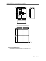
Diesel Screw Compressor Controller MAM900D(Pressure converter V1.0) USER MANUAL Shenzhen Plot Electronic Co., Ltd Address:4-5F,5 Bldg,Highstar Industry Park,Gangtou Community, Bantian,Longgang District,Shenzhen City,China Telephone: (+86 0755)83173599 / 83172822 Postal code:518129 Fax:(+86 0755)83172966 E-mail:[email protected] Website:www.pltsz.com MAM-900D Diesel screw compressor controller Content 1,Product Overview.........................................................................................................................3 2,Product Feature............................................................................................................................3 3,Main Technical Parameter ..........................................................................................................3 4,Button Explanation ......................................................................................................................4 5,Parameter view and set.............................................................................................................6 6,Mechanical、Electrical Installation .........................................................................................10 7,Control principle ........................................................................................................................12 8,Troubleshooting..........................................................................................................................13 9,Electronic Diagram ....................................................................................................................14 Page 2 Total: 14 MAM-900D Diesel screw compressor controller 1,Product Overview MAM-900D diesel air compressor controller is automatical air compressor monitoring system controlled by high-performance single chip micro computer.MAM-900D adopts the newest MCU and combine with most advanced control technology, it can accurately detect and display the speed, oil pressure, air temperature, water temperature, diesel level, discharge air temperature and so on. Also, based on user data set,MAM-900D can be used to monitor the above data and send corresponding control signal which can transfer to alarm signal and give user hint. 2,Product Feature Advanced micro computer control with high reliability Real time detection and display of diesel compressor data Adopt advanced control technology,enable compressor work stable and reliable . Strong anti-interference ability Resistance for bad circumstance such as vibration,high and low temperature,humidity and -salt mist Easy installation and operation Communication extension function 3,Main Technical Parameter 1.Work circumstance ① Work temperature:-30℃~+80℃;Humidity:≤98%;Vibration resistance>4g。 ② 2 Vibration:2~25Hz,Amplitude:1.6mm;25~100Hz,Acceleration:±40m/S 。 2.Speed measurement ① Measurement range:0~9999rpm/min。 ② Measurement error:≤±1rpm/min(Speed measuring gear is above 60). ③ Highest signal frequency:50KHz. ④ Sensor:Reluctance speed sensor. 3.Pressure Measurement ① Measurement range: Oil pressure: 0.00~1.00MPa; Discharge air pressure : 0.00~2.50MPa ② Measurement accuracy:0.5 ③ Sensor:HUBA high temperature type ;4~20mA pressure sensor. Page 3 Total: 14 MAM-900D Diesel screw compressor controller 4.Discharge air temperature measurement ① Measurement range:-50℃~+150℃。 ② Measurement accuracy:0.5 ③ Sensor:Cu50 copper resistance sensor 5.Liquid coolant temperature measurement ① Measurement range:-50℃~+150℃。 ② Measurement accuracy:0.5 ③ Sensor:Cu50 copper resistance sensor 6.Diesel level measurement ① Measurement range:full range measurement。 ② Measurement accuracy: 1%。 ③ Sensor:variable resistance type liquid level sensor.The-measurement data and the ------------corresponding resistance data is as below: Measurement data Resistance data 0% ≤4 Ω 50% 63Ω 100% ≥126Ω 7.Discharge air pressure detect:the stop signal is caused by the fluctuation of discharge air ------pressure. 8.Oil filter block, pressure alarm check and generator check 9.Run time Measurement range:0~999999H。 10.Display 0.5 inch highlight digital display 11.System power supply DC24V±30% 4,Button Explanation 1、Display explanation: ①.Speed:Display the engine speed;Display the corresponding serial number after --------entering setting mode. ②.Oil pressure:Display the oil pressure;Display the corresponding parameter after -------entering setting mode. ③.Air temperature:Display the air temperature;Display the time parameter after Page 4 Total: 14 MAM-900D Diesel screw compressor controller -------entering setting mode。 ④.Water temperature:Display the water temperature(liquid coolant temperature) ⑤.Diesel level:display the percentage of diesel level ⑥.Pressure:Display the air pressure. 2、Indicator Explanation: ①.Charge indicator:Extinguish when the generator is running . ②.Preheat indicator:Indicate the preheat status of generator ③. Operation indicator: illuminated when the diesel compressor is running ----------normally;Blink once after set and save data;Blink constantly when error ----------occurred-in saving or reading data,and will stop blink after user reset and ----------save the data correctly ④.Alarm indicator:When speed ,oil pressure,air temperature,water temperature or --------diesel level alarm or fail,the corresponding display window will blink.For --------system prewarning,the alarm indicator will blink,For system failure,alarm --------indicator will be illuminated. ⑤.Pressure alarm indicator:Alight when theAIR P contactor is closed and alarm signal is generated ⑥.Oil indicator:Indicate the oil absorption and filtration status. 3、 Button explanation: ①.Menu/confirm:Press this button to enter or exist para setting menu ,or save the ---------data set. ②.Move button:In data viewing status,press this button to enter;In data ---------setting status,press this button to move;After eliminating alarm,press this ---------button -to reset indicator light and indicator window. ③.Revise/timing:In data setting mode,press this button to revise the data; In data viewing status,press this button to move to the next menu; In normal working menu,press this button to display the running hour -------------------of compressor 4、Key switch、select switch、start button switch: ①.Off position:Move key switch to this position to turn off controller power ②.On position: Move key switch to this position to turn on controller power。 ③.Start button:After power on,press this button to turn on engine。 ④.Preheat position:After power on,move key switch to this position to heat the ----------diesel compressor. ⑤.Stop position:When diesel compressor is running, move select switch to this ------------position to stop motor. Page 5 Total: 14 MAM-900D Diesel screw compressor controller 5,Parameter view and set The parameter has been set by manufactory and is not necessary to modify normally.User can modify the relatively parameter by three buttons “ MENU/SET ” , ” SWIFT ” , ” ALTER/TIMER”.In main menu, Press “MENU/SET” to enter password verification menu.The first data starts blinking,press “ ALTER/TIMER ” to alter the data from 0-9,also user can press “SWIFT” to move to the next data.User can confirm the password by pressing ” MENU/SET ” . The data will stop blinking if password is correct.User can press “ALTER/TIMER”to check the corresponding authority of password (Password is sorted to customer password and factory password.User can check and modify customer parameter by customer password and also user can check and modify customer and factory parameter by factory password ) .The system will return to the main menu if password is not correct. 1.Parameter set Input the correct password to switch to the parameter viewing menu.Modification and ------setting-method is as followed.: ①.In parameter viewing status(data is not blinking),press “ALTER/TIMER”to check the ------corresponding authority of password .Press “SWIFT” the first data bit will blink.Press -----“ALTER/TIMER” to increase the blinking data.Press “SWIFT” to move the blinking data ------to-the next data.Press “MENU/SET” to save the current data and return to the parameter -----viewing-status(the blink stops and operation indicator blink once). Example of parameter modification: User can modify the SPEED ALARM parameter and PROTECTION DELAY ---TIME according to the following steps In main menu,press”MENU/SET ”to enter password verification menu,the first data starts --blinking Press “ ALTER/TIMER ”to modify the current blinking data which is also the first data of -password.Press“SWIFT”,the second data starts blinking,Press“ALTER/TIMER”to-modify the -current blinking data which is also the second data of password.Modify the--third and fourth -password data with the same method.Press “MENU/SET”to confirm the password Enter parameter viewing status after the verification of the password. Press “ALTER/TIMER”to enter to the menu P-06(Pic 5.1.1)(P-06:SPEED ALARM).Press -“SWIFT” to enter modification and setting mode(digital display),The first data of SPEED-COUNTER-ALARM starts blinking,press “ALTER/TIMER”to modify the blinking data and press “SWIFT”to modify the next data with the same method. Page 6 Total: 14 MAM-900D Diesel screw compressor controller Corresponding serials No. of SPEED COUNTER ALARM VALUE SPEED COUNTER ALARM VALUE RESPOND TIME PIC 5.1.1 After the modification of SEEP ALARM and DELAY TIME PROTECTION,press “MENU/SET” to confirm (the data blink stops and operation indicator blink once ).The -system return to the parameter viewing status.User can refer to the -above method to modify--data.(For more parameter code,please refer to “parameter list and explanation”) ②.In parameter view status,press”ALTER/TIMER”to move to the next menu for -----more selection ③.In parameter view status,press”MENU/SET”to return to the main menu to finish -------parameter set 2.Parameter display, list and explanation ①.Parameter display In parameter viewing status,controller display corresponding parameter serials No. In ----------- SPEED COUNTER column. Page 7 Total: 14 MAM-900D Diesel screw compressor controller corresponding parameter serials No. PIC 5.2.1 ②.Parameter list and explanation P-01:Password menu:Input customer password and factory password,user is allowed to check and modify the corresponding parameter.Original password:0000 P-02:Gear No.:Set the gear No. of speed measuring gear P-03:Start speed counter:When speed counter is above this set data, engine is activated and starting circuit is disconnected. P-04:Oil pressure speed counter:When speed counter is below this set data,ignore the oil pressure low signal. P-05:Rated speed counter of diesel compressor P-06:Speed counter alarm:When speed counter is above the set data,compressor will alarm Respond time(S):how long to respond,when set as 9999,this function is invalid P-07:Speed counter stop:When speed counter is above the set data,controller will stop the compressor Respond time(S):how long to respond,when set as 9999,this function is invalid P-08:Oil pressure alarm:When oil pressure is below this set data,controller will alarm Respond time(S):how long to respond,when set as 9999,this function is invalid P-09:Oil pressure stop:when oil pressure is below this set data,compressor will stop. Respond time(S):how long to respond,when set as 9999,this function is invalid P-10: Water temperature alarm:when water temperature is above this set data,controller will alarm Respond time(S):how long to respond,when set as 9999,this function is invalid Page 8 Total: 14 MAM-900D Diesel screw compressor controller P-11:Water temperature stop:when water temperature is above this set data,compressor will stop Respond time(S):how long to respond,when set as 9999,this function is invalid P-12:Air pressure alarm:when air pressure is above this set data,controller will alarm. Respond time(S):how long to respond,when set as 9999,this function-is invalid P-13:Air pressure stop:when air pressure is above this set data,compressor will stop Respond time(S):how long to respond,when set as 9999,this function-is invalid P-14: Air temperature alarm:when discharge air temperature is above this set -data,controller will alarm Respond time(S):how long to respond,when set as 9999,this function-is invalid P-15: Air temperature stop:when discharge air temperature is above this set data,compressor will stop Respond time(S):how long to respond,when set as 9999,this function is invalid P-16:Oil level alarm:when the oil level is below this set data,controller will alarm Respond time(S):how long to respond,when set as 9999,this function is P-17:Oil level stop:When oil level is below this set data,compressor will stop Respond time(S):how long to respond,when set as 9999,this function is invalid P-18:Ex factory date:set the ex factory date of compressor P-19:Standby P-20:Standby P-21:Current run time P-22: Max time limit(H):When the run time of compressor is above this set data,compressor cannot be activated;this function is invalid when set as 0000 P-23 : Low air temperature limit:When the air temperature is below this set data,compressor will fail to stop Respond time(S):how long to respond,when set as 9999,this function is invalid Page 9 Total: 14 MAM-900D Diesel screw compressor controller P-24:Low water temperature limit:When the water temperature is below this set data,compressor will fail stop Respond time(S):how long to respond,when set as 9999,this function is invalid P-25:Oil pressure sensor failure respond time. Respond time(S):how long to respond,when set as 9999,this function is invalid.This protection is not restricted by speed counter. P-26:When error occurred,and the data is set as 9999,D5 will be de-energized,D 12 will be energized until the system is power off;if the data is not set as 9999,D5 will be de-energized and after the delay time,it will energize again,D12 will be energized and after the delay time it will de-energize again. For the motor(Cummins Engines) which will stop oil supply when de-energized ,the data is recommended to set to 9999;For the motor which will stop oil supply when energized,the data is recommended to set to 0005 P-27:Discharge air pressure sensor failure respond time Respond time(S):how long to respond,when set as 9999,this function is invalid.This protection is not restricted by speed counter. 6,Mechanical、Electrical Installation 1,Mechanical、Electrical Installation ①. Install the controller properly to a suitable position ②. Install the speed counter sensor to the shell of speed measuring gear. The gap -----between the sensor and the gear is 0.5~1mm,then tighten up the screw. ③. Install the discharge air temperature sensor,water temperature sensor ,oil pressure -------sensor,and speed counter sensor to the corresponding position and connect with the ------signal input terminal. ④. Connect correctly according to the terminal connection instruction. 2,Mechanical Installation Diagram MAM-900D mechanical installation diagram is as below( PIC 6.2.1) Page 10 Total: 14 MAM-900D Diesel screw compressor controller PIC 6.2.1Product Dimension Diagram PIC6.2.2 Installation Dimension Diagram 3,Electrical Installation Diagram MAM-900D electrical installation diagram is as below(PIC 6.3.1) Page 11 Total: 14 MAM-900D Diesel screw compressor controller PIC 6.3.1 D5 is normally closed terminal for motor( stop oil supply when de-energized type) D12 is normally open terminal for motor(stop oil supply when energized type) 7,Control principle After install and turn on the the controller,controller start normal work status and activate diesel.Execute load and unload operation by pressing load and unload control valve and control button. Based on the measurement data and user set data to send corresponding signal to measure and display the speed counter,water temperature,oil pressure,oil level, discharge air temperature and pressure of diesel compressor.Controller sends alarm signal when detects the data is over the user set data and stop data. Controller sends stop signal when detects the data over stop data.The operation process is as below. 1.Diesel engine preheat When the air temperature is low or for initial start,adjust the select switch to the preheat,output terminal D7(output 24V) is energized and preheater starts working,turn the select switch to off,output terminal D7(output 24V) is de-energized and preheater stops working 2.Diesel compressor starts process When switch the key to power on,controller output terminal D5 is energized(output Page 12 Total: 14 MAM-900D Diesel screw compressor controller 24V),D12 is de-energized.Press start button,controller output terminal D3,D6 are energized(output 24V),the start motor activates diesel engine,oil moment relay is closed to provide oil to engine.After start process,release the button and controller output terminal D3,D6 will be de-energized. 3.Diesel compressor operation process: When the diesel engine is running and switch the pressure control valve to load ,the compressor inlet valve opens and compressor starts loading.When switch the pressure control valve to unload ,the compressor inlet valve closes and compressor starts unloading 4.Diesel normal stop: In power on status,switch the select button to stop,controller output terminal D5 is de-energized and D12 is energized(output 24V), oil maintain relay opens and diesel engine stops running.( Output terminal D5 for engine of stop oil supply when de-energized type such as cummins;D12 for engine of stop oil supply when energized type such as Yuchai engine ) 5,Pressure alarm: When controller digital input terminal D11 connect with power negative pole,controller will alarm and stop. After input terminal D11 disconnect with power negative pole, problem cannot clear automatically. It is requested to cut off power and restart. 6,Oil filter block alarm When the terminal D10 is connected with power negative electrode ,controller will alarm with the oil filter block indicator on,when D10 is disconnected with power negative electrode,controller will not alarm with the oil filter block-indicator off. Note:Compressor needs to have all error clear and reset after failure stop 8,Troubleshooting Failure Reason Method Discharge air temperature high Poor heat dissipation,less oil Check heat dissipation and lubricant quantity Temperature sensor failure Cable break,Cu50 copper resistance sensor failure Check the cable and Cu50 copper resistance sensor Pressure sensor failure Sensor cable break,sensor failure,sensor cable reversed Check the cable and pressure sensor Page 13 Total: 14 + M + G A + D4 D5 + B7 momen t D6 D7 + + Design B8 D8 Approval Check Normal open D3 B6 Diesel maintain D2 B5 Pressure alarm D1 B4 Oil filter block C FSO B3 co Preheater ntactor B B2 Diesel moment B1 Normal close Preheater Air pressure sensor Diesel level sensor Water temperature Air temperature Oil pressure sensor Speed sensor F1 (15A) Diesel maintain Power K4 Starting motor Diesel control valve Generator Starting motor 24VDC 9,Electronic Diagram B9 B10 B11 B12 B13 B14 MAM-900D EH D9 D10 D11 D12 D13 D14 + K4 MAM-900D Diagram Chart Shenzhen Plot Electronic Co., Ltd