1
CYCLIC-Stress Path: MS User's Manual
© 2013 Geocomp Corp.
water through the line until there are no bubbles. (See Q/A 4 above for instructions
to eliminate air bubbles.)
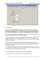
3. Open the System Monitor window (System option in the View menu) and the
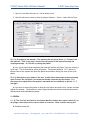
Calibration Summary window (Summary option in the Calibrate menu).
4. Raise the end of the output line to the location that corresponds to the mid-height of
the soil sample. Record the pressure value (in counts) that is shown on the System
Monitor window (the left-hand text field for the pressure reading).
5. On the Calibration Summary window, select the appropriate Channel (Cell Pressure or
Sample Pressure). Type the pressure value you recorded into the Offset text field.
Click the Apply button.
I-3. Q: Can I fill up the cyclic triaxial chamber using the FlowTrac-II unit?
A: It is not practical to fill the test chamber using the FlowTrac-II unit. The total volume
of water required to fill the standard (model 3400) cyclic triaxial chamber is about 2500 ml,
and the total volume capacity of the pump cylinder in the FlowTrac-II unit is 250 ml.
The easiest and most practical way to fill the test chamber is to do so directly from the
water faucet.
*Note: There is no particular requirement for the quality of the chamber water
as long as the water is clean. Water that is drinkable satisfies this requirement.
I-4. Q: What are the minimum specifications for a computer able to handle the new
software for the lab equipment?
A: Any computer that can run Windows XP or Windows Vista will do the job. Typically,
our software programs are only 500 Kb in size. Test data are stored in binary files that are
typically 10 Kb in size. Consequently, very little computer memory and disc space are used.
II. LIMIT SWITCHES
II-1. Q: During the test, a controller error message appears on the screen telling me that a
limit switch is on. What should I do?
A: The first thing to do is to look at the front panel of the FlowTrac-II units to see which
unit has a red limit switch flashing. Close the valve on the test cell to which the line from
that FlowTrac-II unit is connected and then open the System Monitor window. Record the
appropriate pressure value (cell pressure or sample pressure in engineering units.
Disconnect the line from the quick-connect that has the closed valve. Depending on
which limit switch was triggered, refill the pump it was empty or empty it if it was full so that
the pump is about 50% full. Reconnect the line to the test cell valve.
Before opening the valve, reapply the pressure you recorded using the FlowTrac-II LCD
menus and keypad. (From the main menu select Control, then Apply and Maintain Pressure,
Geocomp Corporation · 125 Nagog Park · Acton, MA 01720 · Tel 978-635-0012 · Fax 978-635-0266