1
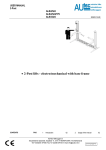
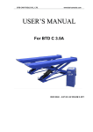
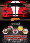
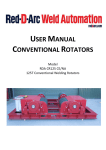
USER MANUAL 2-Post ALM-2528 ALM-3028 ISSUED 27-01-2004 2-Post lifts-electrical mechanical without baseframe AUTEC Hefbruggen bv Industrieterrein Ijsselveld, Vlasakker 11, 3417 XT MONTFOORT, The Netherlands Tel:+31 (0)348-477000 Fax:+31 (0)348-475104 E-mail: [email protected] en/TA-ALM-3028-01 USER MANUAL 2-Post ALM-2528 ALM-3028 CONTENTS 1 Introduction 2 Usage of the manual 3 Description of the lift 4 Technical specifications 5 Safety 6 Operating principles and use 7 Maintenance 8 Troubleshooting 9 Certificate of conformity PAG 02 02 02 03 03 06 07 08 09 1. INTRODUCTION WARNING This manual is made exclusively for operating personnel. Read this manual carefully before usage. This manual contents information about the following parts PERSONAL SAFETY OF THE USER LIFT-SAFETY SAFETY OF LIFTED VEHICLES 2. USAGE OF THE MANUAL The manual is an integral part of the lift, which it should always accompany. The manual must be kept in the vicinity of the lift, in an easily accessible place. The operator and maintenance staff must be able to locate and consult the manual quickly and at any time CAREFULLY READING OF SAFETY INSTRUCTIONS STRONGLY RECOMMANDED ISSUED 27-01-2004 installed. The same applies to the maintenance fitter, who must also posses specific and specialised knowledge (mechanical, engineering) needed to perform the operations described in the manual in complete safety. The words “operator” and “maintenance fitter” used in this manual are construed as follows: OPERATOR: person authorised to use the lift. MAINTENANCE FITTER: person authorised for routine maintenance of the lift. The minimum legal age of the operator is 18 years. 3. DESCRIPTION OF THE LIFT (Fig.1) 2-post Electro mechanical lift model ALM-2528 and ALM-3028 are anchored to the ground, and is designed and manufactured for lifting vehicles and vans and holding them in elevated position. The main parts of the lift are: fixed structural unit(base and post) mobile unit (carriage and arms lift units control panel safety devices Control panel (Fig.3) The electrical control panel includes: Master switch (11) Lift button (12) Descend button(13) Synchronisation indication (14) THE IS The manufacturer declines all responsibility for injury to persons or damage to vehicles or objects due to improper use. This manual indicates only the operative and safety aspects that may prove useful to the operator and maintenance worker, in better understanding the structure and operation of the lift and for best use of the same. In order to understand the terminology used in this manual, the operator must have specific experience in workshop, service, maintenance and repair activities, the ability to interpret correctly the drawings and descriptions contained in the manual and be acquainted with the general and specific safety rules relevant to the country in which the machine has been Fig.3 Fig.1 Fig.2 illustrates the various parts making up the lift: 1. Command side: the side of the rack, which includes the area, reserved for the operator with access to the control panel. 2. Serviceside : the side opposite to the command side 3. Rear: long arm side 4. Front: short arm side 5. Driving direction: driving direction with vehicle-engine in front SAFETY DEVICES These include: Arm lock system and footguards on arms Safety cable for lead nut en obstacle stop Post limit switches Electrical safety devices Electronic synchronisation to prevent height differences. AUTEC Hefbruggen bv Industrieterrein Ijsselveld, Vlasakker 11, 3417 XT MONTFOORT, The Netherlands Tel:+31 (0)348-477000 Fax:+31 (0)348-475104 E-mail: [email protected] en/TA-ALM-3028-02 USER MANUAL 2-Post ALM-2528 ALM-3028 4. TECHNICAL SPECIFICATIONS ALM-2528 CAPACITY : 2.500 kg Lifting time: 55 sec Descend time: 55 sec Total weight: 785 kg Noise Level: 70-dB(A)/1m Operation temperature: -10 oC / +50 oC Working environment: indoor Dimensions: Fig.4 ALM-3028 CAPACITY : 3.000 kg Lifting time: 55 sec Descend time: 55 sec Total weight: 785 kg Noise Level: 70-dB(A)/1m Operation temperature: -10 oC / +50 oC Working environment: indoor Dimensions: Fig.4 ISSUED 27-01-2004 Lift rack model ALM-2528 and ALM 3028 can be adapted to virtually all vehicles, which not exceed the max. weight and / or the following maximum dimensions: MAXIMUM DIMENSIONS OF VEHICLES TO BE LIFTED Maximum width 2200 mm Maximum wheelbases: 3000 mm The underbody of cars with low ground clearance may interfere with the structure of the lift. Pay particular attention in the case of low body sports cars It is vital to read this chapter of the manual carefully and from beginning to end as it contains important information regarding the risks that the operator or maintenance fitter may be exposed to in the eventuality that the lift is used incorrectly. The following text contains clear explanations regarding certain situations of risk or danger that may arise during the operation or maintenance of the lift. WARNING The lifts are designed and built to lift vehicles and hold them in the elevated position in an enclosed workshop. All other uses of the lift are unauthorised. In particular, the lift is not suitable for: washing and respray work. creating raised platforms for personnel or lifting personnel. use as good lift. use as a lift jack for lifting vehicle bodies or changing wheels ELEKTRIC MOTOR ALM-2528 and ALM-3028 Electric motor power: 2x3, 0 kW Voltage: 400V 3ph. +/- 5% Frequency: 50 Hz Absorption: 230V:36A 400V: 16A No. poles: 4 Speed: 1400 rpm The manufacturer disclaims all liability for injury to persons or damage to vehicles and other property caused by incorrect and unauthorised use of the lift. Fig.5 Always keep the capacity of the lift in mind in the case of vehicles with particular characteristics like vans, small buses etc. The safety-area (Fig.6) is determined by the dimensions of the vehicle. During lift and descent movements, the operator must remain in the command station (1) as defined in figure 6. The presence of persons inside the danger zone (2) in the same figure is strictly prohibited. The presence of persons beneath the vehicle during operations is permitted only when the vehicle is parked in the elevated position. ALWAYS CHECK MAXIMUM LOAD CAPACITY AND LOAD DISTRIBUTION IN THE CASE OF LARGER VEHICLES. MAX.2500 kg ALM-2528 MAX.3000 kg ALM-3028 Fig.6 WEIGHT OF THE VEHICLE Fig.4 5. SAFETY DO NOT USE THE LIFT WITHOUT PROTECTION DEVICES OR WITH AUTEC Hefbruggen bv Industrieterrein Ijsselveld, Vlasakker 11, 3417 XT MONTFOORT, The Netherlands Tel:+31 (0)348-477000 Fax:+31 (0)348-475104 E-mail: [email protected] en/TA-ALM-3028-03 USER MANUAL 2-Post ALM-2528 ALM-3028 THE PROTECTION DEVICES INHIBITED. FAILURE TO COMPLY WITH THESE REGULATIONS CAN CAUSE SERIOUS INJURY TO PERSONS, AND IRREPERABLE DAMAGE TO THE LIFT AND THE VEHICLE BEING LIFTED. GENERAL PRECAUTIONS The operator and the maintenance fitter are required to observe the prescriptions of accident prevention legislation in force in the country of installation of the lift. Furthermore, the operator and maintenance fitter must: always work in the scheduled working area as shown in the manual. never remove or deactivate the guards and mechanical, electrical, or other types of safety devices. read the safety notices affixed to the machine and the safety information in this manual. In the manual all safety notices are shown as follows: ISSUED 27-01-2004 position, together with the protection devices adopted by the manufacturer to reduce all such hazards to the minimum: LONGITUDINAL AND LATERAL MOVEMENT Longitudinal movement is considered the backward and forward shifting of the load. Lateral movement implies the shifting to the left or right of the vehicle especially during the lifting phase on the rack. These movements can be avoided by positioning the vehicle correctly on the arm disk support plates. Lift the vehicle only on the by the manufacturer of the vehicle recommended lifting points. Adjust the support plates on the same height by loosening or tightening. WARNING Do not move the vehicle in relation to the arms or adjust arms and disk support plates until the arms have been totally lowered, i.e. the disk support plates must be free from all contact with the vehicle. It is extremely important that the vehicle is positioned on the rack so as to achieve correct load distribution on the arms (Fig.7 + Fig.8). The vehicle engineside must always rest on the short arms! DANGER: Indicates imminent danger that can result in serious injury or death. WARNING: Indicates situations and/or types of manoeuvres that are unsafe and can cause injuries of various degrees or death. RISKS AND PROTECTION DEVICES The risks to which operators or maintenance fitters may be exposed when the vehicle is immobilised in the raised For the safety of persons and equipment, make sure that: the hazard area is observed during lifting. the vehicle engine is switched off, the vehicle is in gear, and the handbrake is engaged. the vehicle is correctly positioned. all weight and dimension limits are observed. RISKS DURING VEHICLE LIFTING The following safety devices have been introduced to avoid overloading and damage: In the case of overload: thermal relay appears on the control panel. CAUTION: Indicates situations and/or types of manoeuvres that are unsafe and can cause minor injury to persons and / or damage the lift, the vehicle or other property RISK OF ELECTRIC SHOCK: specific safety notice affixed to the lift in areas where the risk of electric shock is particularly high Fig.8 in the case of damage to the loadbearing nut, a safety nut (ref1 Fig.9) is automatically engaged. Fig.7 to prevent overrun of the mobilepart, an electric limit switch (2) and a steel plate (3) stop are envisaged for the upper part of the post (Fig.10). AUTEC Hefbruggen bv Industrieterrein Ijsselveld, Vlasakker 11, 3417 XT MONTFOORT, The Netherlands Tel:+31 (0)348-477000 Fax:+31 (0)348-475104 E-mail: [email protected] en/TA-ALM-3028-04 USER MANUAL 2-Post ALM-2528 ALM-3028 ISSUED 27-01-2004 RISKS FOR PERSONNEL When the platforms and vehicle are descending, personnel are prohibited from entering the area beneath the moving parts of the lift (Fig.12). The lift operator must not start the manoeuvre until it has been clearly established that there are no persons in potentially dangerous positions. Fig.14 Fig.9 Fig.12 Fig.10 RISKS FOR PERSONS This paragraph illustrates risks to which the operator, maintenance worker or any person near the operating area of the lift may be exposed in the case. RISKS FOR OPERATOR Possible if the operator controlling the lift is not in the specified position at the command panel. When the platforms and vehicle are descending, the operator must never be partly or completely underneath the moving structure. During this phase the operator must remain in the command zone (Fig.11 + Fig.6) RISK OF IMPACT Caused by parts of the lift or the vehicle that are positioned at head height. When, due to operational reasons, the lift is immobilised at relatively low elevations ( less than 1.75 m from the ground) personnel must be careful to avoid impact with parts of the machine not marked with special hazard colouring (Fig.13). RISK OF VEHICLE FALL FROM LIFT This risk could be caused by the incorrect positioning of the vehicle on the arm disk support plates (Fig.15). Or incorrect positioning of the arm disk support plates in relation to the lift. Prevent this by always positioning the arm disk support plates underneath the by the vehicle’s manufacturer recommended pick-up points. Watch out with dismounting heavy parts(engine)-the weight distribution will change. Fig.15 Never lean objects against the posts or leave them in the area where moving parts are lowered (Fig.16). Fig.13 Fig.11 RISKS DUE TO VEHICLE MOVEMENT (Fig.14) Movement may be caused during operations, which involve force sufficient to move the vehicle. If the vehicle is of considerable dimensions or weight, movement may lead to overloading or unbalancing; all measures must be taken to avoid such an occurrence. Fig.16 AUTEC Hefbruggen bv Industrieterrein Ijsselveld, Vlasakker 11, 3417 XT MONTFOORT, The Netherlands Tel:+31 (0)348-477000 Fax:+31 (0)348-475104 E-mail: [email protected] en/TA-ALM-3028-05 USER MANUAL 2-Post ALM-2528 ALM-3028 BOARDING Never board the vehicle and/or turn the engine on when lift is raised (Fig.17). Fig.17 SLIPPING This risk may arise due to spillage of lubricants in the surrounding area. Always keep the area surrounding clean by removing all oil spills (Fig.18). ISSUED 27-01-2004 RISKS RELATED TO INAPPROPRIATE LIGHTING The operator and the maintenance fitter must be able to assure that all the areas of the lift are properly and uniformly illuminated in compliance with the laws in force in the place of installation. RISK OF COMPONENT FAILURE DURING OPERATION Autec has used appropriate materials and construction techniques in relation to the specified use of the machine in order to manufacture a reliable and safe lift. Note however, that the lift must be used in conformity with manufactures prescriptions and the frequency of inspections and maintenance work. 6. OPERATION AND USE (Fig. 20) The lift commands include: Non-detended button that must be held pressed (deadman device) operating at 24 V. Operates the electric motor and mechanisms for raising carriage. DESCEND BUTTON (13) Non-detended type that must be held pressed (deadman device); operating at 24 V. Operates the electric motor and mechanisms for lowering carriage. OPERATING SEQUENCE 1) Lifting points Position rack arms in vehicle manufacturer recommended lift points, then adjust disk support plates to same height. Whenever you lower the lift to the ground, before lifting again, recheck the position of the lift disk support plates on the vehicle chassis. 2) Lifting Turn the masterswitch to position 1, push the lift button. Release the lift button if the vehicle is lifted 40 cm from the ground. Check the position of the vehicle. If the vehicle is positioned correctly. Push the lift button again. 3) Parking Release the lift button if the required height is achieved, now switch the master switch to position 0. Fig.18 RISK OF ELECTRIC SHOCK Risk of electric shock in areas of the lift housing electrical wiring. Do not use jets of water, steam, solvents or paint in the immediate vicinity of the lift (Fig.19). Fig.20 MASTER SWITCH (11) Position 0: The lift is not receiving electrical power: access to panel is possible. The master switch may be locked out to prevent improper use. Position 1: power supplied to lift. 4) Descend After ensuring that no obstacles are present beneath the lift, turn master switch back to position 1, then press button P2 to lower vehicle to the desired height or to the ground. If an obstacle hampers carriage during this phase, the safety cabine will operate to immobilise the lift. Mind: This is not a crushing prevention for persons. Fig.19 LIFT BUTTON (12) AUTEC Hefbruggen bv Industrieterrein Ijsselveld, Vlasakker 11, 3417 XT MONTFOORT, The Netherlands Tel:+31 (0)348-477000 Fax:+31 (0)348-475104 E-mail: [email protected] en/TA-ALM-3028-06 USER MANUAL 2-Post ALM-2528 ALM-3028 OPERATION SYNCHROLIFT (Fig.20 ref14) SYNCHROLIFT is an electronic detection and data management system for automatic levelling of the two trolleys. Two sensors fitted on the motor pulleys detect any faults, and an electronic circuit on the control board enables all the corrections possible for synchronising the level of the trolleys. If no correction is possible, the lift is blocked and the trouble is signalled. A series of LED’s on the front panel (ref.14 Fig.20) give the following indications: L.E.D. No 1 (green): mains power supplied everything OK. L.E.D. No 2 (red): motor overload protection tripped. When this L.E.D. lights up, wait for 3 minutes and then reset the overload relays. Should an overload protection be tripped again, call an authorised service centre. L.E.D. No 3 (green) : battery indicator. This LED is burning in normal operation. L.E.D. No.4 (yellow): SYNCHROLIFT in operation. This LED lights up when synchrolift is levelling the carriages, and goes off when levelling is accomplished (after about 1 second). L.E.D. No 5 (red): this LED lights up to indicate that synchrolift cannot carry out the levelling operation, meaning that there can be a serious fault on the lift. At this point, synchrolift blocks all operation. Now, turn the main switch in the off position, wait for 10 seconds turn the mainswitch in the on position. If this doesn’t work call an authorised service centre. ATTENTION! Inside the control panel there are on the right bottom of the panel two LED’s for bearing screw indication and obstacle protection. These LED’s are burning in normal operation. When a problem occurs the LED’s go out. Fix the problem and check whether the LED’s are burning again. If the problem remains call an authorised dealer. ISSUED 27-01-2004 7. MAINTENANCE Maintenance must be performed exclusively by expert personnel with thorough knowledge of lift operation. During lift maintenance, take all necessary precautions to prevent accidental engagement of the lift: For lubricating the liftparts we recommend the following lubrication products( Fig.21): No. Texaco Shell ESSO Castrol 1. Topbearing Molytex EP 2 Alvania HDX vet 2 Multipurpose vet+moly MS3 grease 2. Side guidance Teflonspray Teflonspray Teflonspray Teflonspray 3. Arm locking 4. Spindle Molytex EP 2 Meropa 320 Alvania HDX vet 2 Omala 320 Multipurpose vet+moly Spartan 320 MS3 grease Alfa SP320 1. 2. 3. 4. Plan of periodical lubrication Topbearing – 3 months Sideguidance – 3 months Arm locking – 3 months Spindle– 1 month Fig.21 8. TROUBLESHOOTING AUTEC Hefbruggen bv Industrieterrein Ijsselveld, Vlasakker 11, 3417 XT MONTFOORT, The Netherlands Tel:+31(0)348-477000 Fax:+31 (0)348-475104 E-mail: [email protected] en/TA-ALM-3028-07 USER MANUAL 2-Post ALM-2528 ALM-3028 ISSUED 27-01-2004 The trouble searching and the possible repair intervention need the observance of ALL THE SAFETY PRECAUTIONS shown in this manual. PROBLEMS The lift doesn’t rise while pushing the lift button The lift don’t finish the path of lift The lift do not descend while pushing the button Lift blocked Lift doesn’t synchronize POSSIBLE REASON CURE The fuse is burnt out Lift overload Replace the fuse Conform to the scheduled capacity Microswitch(es) not working Fault in electric system Thermal cut-out disconnection Lift overload Line voltage too low Motor driving belts slack Object under lift Fault in electric system Safety cable broken Safety limit switch blocked L.E.D. nr.5 is on The distance between sensor and bolt is to much (more than 2mm). Replace the microswitch (call for assistance) Call assistance Resetting the terminal cut out Conform to the scheduled capacity Check the line voltage Pull the driving belts Remove the object Call for assistance Replace cable (call assistance) Check the bearing nut (call for assistance) Reset the lift (see page 7) Adjust the sensor SPARE ORDERING / REPAIR PROCEDURE To order the spare parts it is necessary to: indicate the lift serial number and the year of manufacturing For spare parts we refer to the next TIB-pages available on request: uni/TE-ALM-3028-01 / uni/TE-ALM-3028-02 / uni/TE-ALM-3028-03 / uni/TE-ALM-3028-04 / uni/TE-ALM-3028-05 ACCESSOIRES ALM-2528 / 3028 ( Fig.22) The lifting pad extensionset ALM 2524/V12 and ALM-2524/V20 are options for the ALM 2528 and 3028 lifts. Every set comprises of 4 lifting extensions. The lifting pad extensions are used: for vehicles with high level lifting points Lifting points that lay more to the inside of the carbide. Without use of the extension the carbody will touch the lifting arms Fig.22 INSTALLATION The installation of the set is very simple. The extension is placed on the top of the normal lifting pads and secured with the locking device. AUTEC Hefbruggen bv Industrieterrein Ijsselveld, Vlasakker 11, 3417 XT MONTFOORT, The Netherlands Tel:+31(0)348-477000 Fax:+31 (0)348-475104 E-mail: [email protected] en/TA-ALM-3028-08 USER MANUAL 2-Post ALM-2528 ALM-3028 ISSUED 11-09-2012 9. CERTIFICATE OF CONFORMITY AUTEC Hefbruggen b.v. Vlasakker 11 NL 3417 XT Montfoort The Netherlands hereby declares that the lift type A: ALM-2528 B: ALM-3028 has been manufactured in accordance with the specifications FOLLOWING THE GUIDELINES OF 14-06-89 ((89/392/EEG), ammended by guidelines 91/368/EEG, 93/44/EEG, EN 60204-1, EN 414, EMC 89/336/EEG, 73/23/EEG, EN 292-1: 1992, EN 292-2: 1992, EN 394, EN418, Pr EN 1493 aug. 1994 and that the lift complies with the said specifications an guidelines, and after inspection the lift has been awarded with a CE-certificate nr.04 205-1194/95 issued in 1997 by: RWTÜV Essen (Duitsland) AUTEC Hefbruggen bv Industrieterrein Ijsselveld, Vlasakker 11, 3417 XT MONTFOORT, The Netherlands Tel: +31 (0)348-477000 Fax: +31 (0)348-475104 E-mail:[email protected] en/TA-ALM-3028-09