1
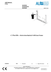
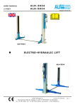
USER-MANUAL 4-Column AL3044 AL4044 AL4044/VS AL4044/VANS AL5044 AL5044/T ISSUED 22-7-2008 • 4 Colomn lifts–electro hydraulic AUTEC Hefbruggen bv Industrieterrein IJsselveld, Vlasakker 11, 3417 XT MONTFOORT, The Netherlands Tel: +31 348 477000 Fax: +31 348 475104 E-mail:[email protected] en/TA-AL3044-01 USER-MANUAL 4-Column AL3044 AL4044 AL4044/VS AL4044/VANS AL5044 AL5044/T AUTEC Hefbruggen bv Industrieterrein IJsselveld, Vlasakker 11, 3417 XT MONTFOORT, The Netherlands Tel: +31 348 477000 Fax: +31 348 475104 E-mail:[email protected] ISSUED 22-7-2008 USER-MANUAL 4-Column INDEX OF CONTENTS 1 Introduction 2 How to use this manual 3 Description of the lift 4 Technical specifications 5 Safety 6 Controls and operation 7 Maintenance 8 Troubleshooting 9 Conformity declaration AL3044 AL4044 AL4044/VS AL4044/VANS AL5044 AL5044/T PAG 02 02 02 03 03 05 06 06 07 1. INTRODUCTION CAUTION This manual is intended for factory personnel who are going to operate the lift; read the Manual before you use the platform in any way or perform any actions on it. This Manual contains important information about the following points : THE PERSONAL SAFETY OF THE OPERATOR PREVENT DAMAGE TO THE LIFTS PREVENT DAMAGE TO THE VEHICLE ISSUED 22-7-2008 specific experience in industrial work, service, maintenance and repair activities, and must also possess the ability to explain the drawings and the descriptions contained in this manual to other people. At the same time he must also be aware of the general and specific safety regulations which apply in the country where the lift is being installed. The word “operator”, which has been used throughout this manual, refers to a person who is authorised to use the platform. The minimum legal age for using the lift is 18 years. 5. Sliding direction : Direction in which the vehicle will come sliding in, with the motor-side of the vehicle in the front. 3. DESCRIPTION OF THE LIFT (Fig.1) 4-colomn electro hydraulic lift model AL3044 / AL4044 / AL5044 is anchored to the ground and is designed and manufactured for lifting passenger cars and delivery vans and to hold them in a certain lifted position. The main components of the lift are: welded construction-parts (frame en columns) Lifting components Control box Safety devices Fig.2 CONTROL BOX (Fig.3) The electrical controlbox consists of the following : • Main switch (11) • Lift button (12) • Descend button (13) • Locking (14) 2. HOW TO USE THIS MANUAL The Manual forms part of the lift and must be available for reference in the immediate vicinity of the lift at all times. The operator of the lift must be able to refer to the Manual quickly and at any given moment. IT IS STRONGLY RECOMMENDED THAT YOU SHOULD FIRST CAREFULLY READ THE SAFETY INSTRUCTIONS. The manufacturer hereby refuses to accept any responsibility for injury to persons or damage to equipment or property if it appears that incorrect handling of the lift has taken place. This instructions manual only describes the operating- and safety aspects which persons who are installing the machine need to know. In order to understand the terminology used in this manual, it is necessary that the person performing the installation work should have Fig.1 See Fig.2 for the following terms: 1. Operation side/ Control side 2. Serviceside: the side against the control side 3. Rear: the side of the drive-on ramps 4. Front: the side against the rear side Fig.3 SAFETY ARRANGEMENTS The cable Cable protection Microswitches Leakkage / fracture protection Electrical protection Foot-protection Lift locking On- and overdrive protection AUTEC Hefbruggen bv Industrieterrein IJsselveld, Vlasakker 11, 3417 XT MONTFOORT, The Netherlands Tel: +31 348 477000 Fax: +31 348 475104 E-mail:[email protected] en/TA-AL3044-02 USER-MANUAL 4-Column AL3044 AL4044 AL4044/VS AL4044/VANS AL5044 AL5044/T 4. TECHNICAL SPECIFICATION 1= AL 3044 2= AL 3044 / 1-Ph 3= AL3044 / MOT 4= AL 4044 / VANS 5= AL 4044 / MOT 6= AL 3044/T 7= AL 4044/VANS/T 8= AL 5044 9= AL 5044/T 10 = AL 4044/VS Total weight Noise level Working temperature Working enviroment Dimensions 800 kg 77dB (A)/1m -10 oC / +50 oC Covered Fig.4 AL 5044 / AL5044/T Capacity Lifting time Descending time Total weight Noise level Working temperature Working enviroment Dimensions 5.000 kg 35 sec 35 sec 1100 kg / 1200 kg 77dB (A)/1m -10 oC / +50 oC Covered Fig.4 ELECTRIC MOTOR AL3044 / AL4044 / AL5044 Motor power 3 Kw Voltage 400 Frequency 50 Hz Absorption 400V -3Ph: 9,5A 230V –3Ph: 16,5A No. wires 5 Speed 1445 Fig.4 A B C D E F G H 1 2 273 0 400 273 0 400 3 4/5 6 7 8 9 10 3180 2730 3190 3190 3190 630 400 630 630 630 319 0 500 868 590 / 840 868 / 988 590 / 840 590/ 840 590/ 840 2322 2780 2322 2780 2780 2780 4110 4800 4110 4800 5200 5200 4800 5800 4800 5800 6200 6200 2470 2470 2470 2470 2470 2470 Min.120 Max.1850 120 / 1950 170 / 1830 150 / 1950 130/ 1950 170/ 1950 273 0 500 AL 3044/1-Ph Capacity 2.500 kg AL 3044 AL3044/MOT AL 3044/T Capacity 3.000 kg Lifting time 35 sec Descending time 35 sec Total weight 650 kg Noise level 77dB (A)/1m Working temperature -10 oC / +50 oC Working enviroment Covered Dimensions Fig.4 AL 4044, AL4044/VANS, AL 4044/MOT, AL4044/VS Capacity 4.000 kg Lifting time 35 sec Descending time 35 sec 810/ 101 6 278 0 480 0 580 0 247 0 130/ 195 0 ELECTRIC MOTOR AL3044 1ph Motor power 3Kw Voltage 230 V Frequency 50 Hz Absorption 16A Quant. wires 3 Speed 1445 THE WEIGHT OF THE VEHICLE The lift can be used for practically all vehicles provided that the maximum loading capacity is not exceeded. Always keep in mind the lifting capacity of the lift in the case of vehicles with special characteristics (such as delivery vans and other types of vans, etc.). The safety zone (Fig. 6) is to some extend determined by the dimensions of the vehicle to be lifted. ISSUED 22-7-2008 It is important to read point number 5 of this manual properly since it contains important information about the risks which the operator of the lift will be exposed to if the lift is not used properly. In what follows, you will find information about how to avoid dangerous situations. WARNING The lift is designed and constructed to lift vehicles and to hold them in a certain position in a covered working place. Any other form of use is not permitted. In short, the lift is not suitable for the following purposes: Washing and spraying work. To be used as a device for applying force. To be used as a goods lift. To be used as a jack or for lifting vehicles for changing wheels. The manufacturer hereby refuses entertain any claims for damages arising in connection with injury to persons or damage to vehicle or other property caused due to incorrect and/or unauthorised use of the lift. During lifting- and lowering movements, the operator must be within the zone of operation (1), as shown in Fig. 6. The presence of any person in the safety zone (2) is strictly forbidden. The presence of persons under the vehicle is only permitted if the vehicle is parked in the lifted position. CHECK THE MAXIMUM LOADING CAPACITY, THE MAXIMUM WEIGHT AND THE DISTRIBUTION OF LOAD IN THE CASE OF LARGE VEHICLES MAX.3000 kg AL 3044 MAX.4000 kg AL 4044 MAX.5000 kg AL 5044 5. SAFETY Fig.6 USE THE LIFT ONLY IF ALL THE SAFETY ARRANGEMENTS ARE WORKING PROPERLY. IF THESE RULES ARE NOT FOLLOWED, SERIOUS INJURY COULD AUTEC Hefbruggen bv Industrieterrein IJsselveld, Vlasakker 11, 3417 XT MONTFOORT, The Netherlands Tel: +31 348 477000 Fax: +31 348 475104 E-mail:[email protected] en/TA-AL3044-03 USER-MANUAL 4-Column AL3044 AL4044 AL4044/VS AL4044/VANS AL5044 AL5044/T BE CAUSED TO PERSONS AS WELL AS IRREPARABLE DAMAGE TO THE LIFT AND THE VEHICLE ON THE LIFT. media which have been installed, in order to limit the possible dangers. GENERAL PRECAUTIONS: HAZARDS ASSOCIATED WITH LIFTING OF A VEHICLE The following provisions have been made to avoid damage from excess weight: 1. Cable breach security: in each column a safety bar (catch bar) has been fitted parallel to the cable, which in the event of the cable breaking will automatically support the raised section 2. Microswitches: microswitches have been fitted to the ends of the crossbeams to control the cable voltage. Should the voltage to the cable be interrupted, by for example impact with an obstacle during lowering, the lifting bridge will stop its descent. 3. Leakage and breakage protection: a pipe-breakage valve has been fitted in the cylinder head that will in the event of pipe breakage reduce the rate of descent of the tracks. • The operator is bound to follow the regulations which apply in the country in which these lifts are installed. In addition, the operator must : • Always work in the operator area as designated in the manual. • Never remove the protective guards or dismantle or shut down the mechanical, electrical or other types of safety arrangements. • Read the safety regulations relating to the lift and take cognisance of the safety information provided in this manual. The following terms have been used in this manual to describe the various types of risk : DANGER : there is a direct possibility of danger which could lead to serious injury or death. 4. 5. Acoustic signal: the lifting bridge will during its descent produce an acoustic signal. Lifting bridge locking: next to the catch bar in each column a locking mechanism has been installed. This consists of a strip in which grooves have been cut at regular intervals and with them slide locks that are shot into them by a spring when the raising/lowering button is released. Roll-on and roll-off protection: there is on the front end of the tracks roll-off protection, on the rear side at the point of entry these are automatically elevated upon lifting. Thermal protection: the electric motor is fitted with thermal protection, which guards the motor from overheating. WARNING: this indicates situations and/or actions which are unsafe and could lead to injuries of various types except death. CAUTION : this indicates situations and/or actions, which are unsafe and could lead to light injuries to persons and/or damage to the lift, the vehicle or other properties. 6. RISK OF DAMAGE DUE TO ELECTRICITY : Special safety arrangements have been made on the lift in places where the risks are very high. 7. RISKS AND PROTECTIVE MEDIA The risks to which the operator is exposed when the vehicle is in a raised position, together with the protective RISKS TO PERSONS ISSUED 22-7-2008 This paragraph describes the risks to which the operator or any other person near the working area where the lift is in operation, in case the lift is not used in the appropriate manner. RISKS FOR THE OPERATOR (Fig. 8) This risk arises in cases where the operator is not standing at the appointed place at the control cabinet; when the lift with the vehicle is being lowered, it is not permissible for the operator to stand below the descending system and its load to any extent. It is imperative that the operator must be standing in the operating zone during the lifting and lowering operation. Fig.7 RISKS TO PERSONNEL When the lift with the vehicle is moving downward, it is not permissible for any of the personnel to enter the room or walk under the (downward) moving parts of the lift.(Fig. 8) The operator should not start the motion of the lift until he has assured himself that there are no persons within the danger zone. Fig.8 CAUTION AGAINST COLLIDING ANY PART OF THE SYSTEM This is relevant in cases where the lift or the vehicle are at head height. When the lift is at standstill at a lower level, the personnel should take care to see that they do not bump into parts of the lift or the vehicle. (Fig.9) AUTEC Hefbruggen bv Industrieterrein IJsselveld, Vlasakker 11, 3417 XT MONTFOORT, The Netherlands Tel: +31 348 477000 Fax: +31 348 475104 E-mail:[email protected] en/TA-AL3044-04 USER-MANUAL 4-Column AL3044 AL4044 AL4044/VS AL4044/VANS AL5044 AL5044/T ISSUED 22-7-2008 LOWERING BUTTON (13)Recessed button that must be held during lowering (so-called dead man’s handle). Fig.9 Never rest any fittings or other objects against the platform and never place such objects under the platform when it has a load mounted on it, since this can impede the lowering operations and may cause the vehicle to fall off the platform (Fig. 10) Fig.10 Never enter the vehicle or start the motor when the vehicle is on the lift (Fig.11) Fig.13 RISKS DUE TO INSUFFICIENT LIGHTING The area surrounding the lift must be properly lighted according to the legal requirements applicable in the place of installation. RISKS OF USE/MAINTENANCE Autec uses material of the highest quality in its lift. These must be used according to the standard specified, and maintenance must be carried out regularly. 6. CONTROLS (Fig. 14) The control unit contains: RISK OF SLIDING OUT This risk can be overcome by avoiding the spillage of oil or grease in the area surrounding the lift (Fig. 16). Apart from that, any oil spillage which may occur should be thoroughly removed from the spot. Fig.14 RISK OF ELECTROCUTION Never spray water or steam or solvents or paint in the area immediately surrounding the platform and the control cabinet (Fig.13) 6. SEQUENCE OF OPERATION 1) Positioning of vehicle Drive the vehicle carefully onto the lifting bridge. Turn off the engine and apply the handbrake. Check that the vehicle is properly positioned. 2) Raising Turn the main switch (11) to position 1. Check that the vehicle is safely positioned on the lifting bridge. When this is the case press the raising button (12) until the desired height is reached. 3) Parking Release the raising button when the desired height has been reached. Then press the parking button (14). The bridge will now decline slightly and the safety locks automatically engage. Fig.11 Fig.12 LOCKING (14) This button must be depressed to allow the lifting bridge to sink into the locking mechanism MAIN SWITCH (11) Position 0: There is no power supply to the lifting bridge. A lock can be installed in the main switch to prevent from unauthorized parties using and/or operating the lifting bridge. RAISING BUTTON (12) Recessed button that must be held during lifting (so-called dead man’s handle). 4) Lowering Check first that there are no obstacles under the lifting bridge and then depress the lowering button(13) to enable the vehicle to sink to the height required or to the safety height (the lifting bridge will first rise slightly to release the locks). When descending the lift will stop at the safety height of approx. 20cm. 5) Lowering from safety height For lowering the last 20 cm please push the button(14). The lift will now lower to the ground while a horn produces a warning signal. Emergency lowering AUTEC Hefbruggen bv Industrieterrein IJsselveld, Vlasakker 11, 3417 XT MONTFOORT, The Netherlands Tel: +31 348 477000 Fax: +31 348 475104 E-mail:[email protected] USER-MANUAL 4-Column AL3044 AL4044 AL4044/VS AL4044/VANS AL5044 AL5044/T ISSUED 22-7-2008 In the event of breakdown the lifting bridge can be lowered in the following manner: • lower gently. When the bridge is in its lowest position, turn the valve back to its initial position. Old model: Loosen the securing nut of the manual lowering valve with the appropriate spanner and use an Allen key to open the manual opening valve by slowly turning clockwise. The bridge will now lower. When the bridge is in its lowest position, turn the valve back to its initial position. Fig.15 • New model Fig.16 Loosen the securing nut of the manual lowering valve with a size-13 openended spanner and use a 5 mm Allen key to gently open the valve (turn anticlockwise, but do not screw the valve completely free!). The bridge will now 7. MAINTENANCE The lift must be inspected at least once a year according to the CE-Ordinance by a person duly authorised to inspect the same. In addition, preventive maintenance as required by the CE-Ordinance should be done once a year on the lift (please enquire with AUTEC for details of our maintenance contracts). We recommend the following lubricants for the lubrication of the lift: No. Texaco Shell ESSO 1. Cable pulley axes 2. Cabels Molytex EP 2 Alvania HDX vet 2 Multipurpose vet+moly Cable oil . Bel-ray 6 in 1 Castrol Smeerschema MS3 grease 1 x a year 1 x a year 8. TROUBLE SHOOTING Detecting and correcting faults can only be done if the SAFETY REGULATIONS as described are followed in full. L REPAIRS TO THE SAFETY ARRANGEMENTS AND ELECTRICAL COMPONENTS IN THE BRIDGE SHOULD ONLY BE CARRIED OUT BY AUTHORISED PERSONNEL. PROBLEMS POSSIBLE CURE Lift rises but will not lower. • • • Microswitches are depressed Coil of magnetic valve is not functioning Spindle of magnetic valve is jammed in valve Pushbutton ‘lower is defective • • • Check Replace coil Clean with compressed air • Replace • • Replace Colette Replace magnetic valve • • • • Colette of the cylinder worn Magnetic valve of the hydraulic unit does not close One-way valve is not closing No power supply Fuse defective Motor overheated • • • • Replace / clean one-way valve Check valve Replace Allow motor to cool • Insufficient oil • Replenish oil to level plug • The lifting lift lowers autonomously • • The motor does not function When the lifting lift has reached its highest point the oil pump makes a suspicious sound. AUTEC Hefbruggen bv Industrieterrein IJsselveld, Vlasakker 11, 3417 XT MONTFOORT, The Netherlands Tel: +31 348 477000 Fax: +31 348 475104 E-mail:[email protected] en/TA-AL3044-06 en/TA-AL3044-05 USER-MANUAL 4-Column Lifting lift will not lower AL3044 AL4044 AL4044/VS AL4044/VANS AL5044 AL5044/T • • The locking device is engaged Fuse in control unit is broken ISSUED 22-7-2008 • • Check air pressure Replace fuse SPARE ORDERING / REPAIR PROCEDURE To order the spare parts it is necessary to: indicate the lift serial number and the year of manufacturing For spare parts we refer to the next TIB-pages available on request: UNI-TE/AL-3044 9. CERTIFICATE CONFORMITY AUTEC Hefbruggen b.v. Vlasakker 11 NL 3417 XT Montfoort The Netherlands Declares hereby that lifttype AL3044 AL4044 AL5044 has been manufactured in accordance with the specifications following the guidelines of ((89/392/EEG), ammended by guidelines 89/63EEC, 91/368/EEC, 93/68/EEC, 73/23/EEC and that the lift complies with the said specifications an guidelines, and after inspection the lift has been awarded with a CE-certificate 04 205-3461/96 (AL 3044) 04 205-3462/96 (AL 4044 incl. /T, /W, /T/WF, /VS) 04 205-3463/96 (AL 4044/VANS, / MOT) 04 205-14011/10 (AL 5044, /T) issued by, RWTUV Duitsland AUTEC Hefbruggen bv Industrieterrein IJsselveld, Vlasakker 11, 3417 XT MONTFOORT, The Netherlands Tel: +31 348 477000 Fax: +31 348 475104 E-mail:[email protected] en/TA-AL3044-07 USER-MANUAL 4-Column AL3044 AL4044 AL4044/VS AL4044/VANS AL5044 AL5044/T ISSUED 22-7-2008 APPENDIX OI01A INSTRUCTION OF MAINTENANCE HYDRAULIC 4-POST LIFT To be executed activities/ preventive maintenance of a hydraulic 4-post lift. (Required time: 75 min.) Once a year or as much times as needed regarding the intensity of use or because of climatologically circumstances, the following activities of maintenance have to be carried out: 1. 2. 3. 4. 5. 6. 7. hoisting cables cable pulley air cylinders and pipes electric wiring hydraulic cylinder and pipes floor securing securities 1 The hoisting cables have to be checked on damage or broken windings, then sweep clean the cables with a not fluffing cloth and lubricate again with special oil. At the same time, it has to be checked if the lift is still hanging level in its cables, if not is has to be adjusted. 2 The cable pulleys, both in the cross beam and under the platform, have to be disassembled, cleaned, checked and greased. The following procedure has to be carried out: Hang the lift in the interlocking on such a height that working on the cable pulleys in the crossbeam is possible. Then open the emergency pocket valve and pull at the cables to switch off the voltage, check if the lift is hanging solidly in its interlocking. Now it is possible to remove the pins of the cable pulleys in the cross beam, check these pins on excessive wastage. Check as well the bearings in the cable pulleys on excessive wastage and clean both the pin and the bearings and grease them again and put them back together. After assembling back the cable pulleys check if the cables are lying right on the roller and if the lever of the chain fracture security is guided behind the cables in the right way. To pull the cables taut again, you have to open the control unit and push hand-operated the up-relay. To check the cable pulleys under the platform you have to repeat this procedure with the difference that the pulleys under the platform in contrary to the pulleys in the cross beam can fall out of the platform. To prevent this you can put a pen or a thick screwdriver in the pinhole of the pulleys after pulling out the pin. After assembling the pulleys it is very important to check if all the cables are lying on the right pulley again. 3 Check all the air pipes on leakage and if there has not been installed an oil sprayer you have to detach the air pipes from the cylinders and then push the down button; any possible present water in the pipe can go away. Then spout a little bit of thin oil in the pipe and install the pipes again, then check if the interlockings are well functioning. 4 Check all electric wiring on damages, if there are damages replace the concerned wiring. During activities to the electric wiring always put the main switch on zero and block in this position. 5 Check hydraulic pipes, hoses and packings. 6 Check securing bolts with which the lift is attached on the floor and check the posts on standing level. 7 Check the obstruction guards by means of a chock of wood which has to be placed turn and turnabout under one of the hooks of the cross beam, after which you let down the lift on the chock of wood, the lift has to stop descending. REQUIRED LUBRICANTS Pins of the cable pulley Multi-purpose grease AUTEC Hefbruggen bv Industrieterrein IJsselveld, Vlasakker 11, 3417 XT MONTFOORT, The Netherlands Tel: +31 348 477000 Fax: +31 348 475104 E-mail:[email protected] USER-MANUAL 4-Column Cables AL3044 AL4044 AL4044/VS AL4044/VANS AL5044 AL5044/T Cable oil AUTEC Hefbruggen bv Industrieterrein IJsselveld, Vlasakker 11, 3417 XT MONTFOORT, The Netherlands Tel: +31 348 477000 Fax: +31 348 475104 E-mail:[email protected] ISSUED 22-7-2008