1
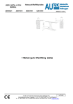
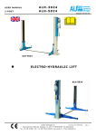
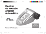
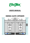
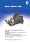
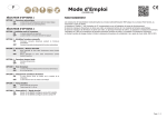
USER MANUAL Scissor ASG-3005 ASG-3005/CAR ASH-3005 ASG-3005/E ASG-4005 ASH-4005 ISSUED 11-02-04 • Wheelfree scissor - electro hydraulic INDEX OF CONTENTS 1 Introduction PAG 02 2 3 How to use this manual 02 4 Technical specifications Description of the lift 02 5 Safety AUTEC Hefbruggen bv Industrieterrein IJsselveld, Vlasakker 11, 3417 XT MONTFOORT, The Netherlands Tel: +31 348 477000 Fax: +31 348 475104 Internet: www.autec.nl - E-mail: [email protected] 03 03 en/TA-ASG-4005-1 USER MANUAL Scissor 6 7 8 9 Controls and operation Maintenance Troubleshooting Conformity declaration ASG-3005 ASG-3005/CAR ASH-3005 ASG-3005/E ASG-4005 ASH-4005 06 07 08 09 1. INTRODUCTION CAUTION This manual is intended for factory personnel who are going to operate the lift; read the manual before you use the platform in any way or perform any actions on it. This Manual contains important information about the following points : THE PERSONAL SAFETY OF THE OPERATOR PREVENT DAMAGE TO THE LIFTS PREVENT DAMAGE TO THE installed. The word “operator”, which has been used throughout this manual, refers to a person who is authorised to use the platform. The minimum legal age for using the lift is 18 years. 3. DESCRIPTION OF THE LIFT (Fig.1) The electro hydraulic lifts models ASG3005 en 4005, ASH 3005 and 4005 are anchored to the ground, and are designed and manufactured for lifting passenger cars and delivery vans and to hold them in a certain lifted position. The main components of the lift are : Welded floor frame Movable parts (supports and arms) Lifting components Control cabinet Safety arrangements. ISSUED 11-02-04 Fig.2 CONTROL CABINET (Fig. 3) The electrical control cabinet consists of the following : 1. Safety switch for completing the last 400 mm of the lowering motion 2. Voltage monitoring lamp 3. Signal lamp/horn 4. Emergency stop button 5. Downward motion button 6. Lifting motion button 7. Main switch ASG-3005 ASG-3005/E ASG-3005/CAR ASG-4005 ASH-3005 ASH-4005 VEHICLE 2. HOW TO USE THIS MANUAL The Manual forms part of the lift and must be available for reference in the immediate vicinity of the lift at all times. The operator of the lift must be able to refer to the Manual quickly and at any given moment. IT IS STRONGLY RECOMMENDED THAT YOU SHOULD FIRST CAREFULLY READ THE SAFETY INSTRUCTIONS. The manufacturer hereby refuses to accept any responsibility for injury to persons or damage to equipment or property if it appears that incorrect handling of the lift has taken place. This instructions manual only describes the operating- and safety aspects which persons who are installing the machine need to know. In order to understand the terminology used in this manual, it is necessary that the person performing the installation work should have specific experience in industrial work, service, maintenance and repair activities, and must also possess the ability to explain the drawings and the descriptions contained in this manual to other people. At the same time he must also be aware of the general and specific safety regulations which apply in the country where the lift is being Fig.3 Fig.1 See Fig. 2 for the following terms : 1. Operating side : the area in which the operator does his work, and from where he can access the control cabinet. 2. Rear : The side where the support extension pieces are mounted. There is a hydraulic part in the control cabinet of the ASG which consists of an oil tank, a hydraulic pump, an electrical motor, solenoid valves and hydraulic hoses. SAFETY ARRANGEMENTS These include the following : Limit switches Electrical safety arrangements Overpressure valves Hose rupture protection Photocel 3. Front : The side where the cylinder rod is mounted on the frame. 4. Sliding direction : Direction in which the vehicle will come sliding in, with the motor-side of the vehicle in the front. AUTEC Hefbruggen bv Industrieterrein IJsselveld, Vlasakker 11, 3417 XT MONTFOORT, The Netherlands Tel: +31 348 477000 Fax: +31 348 475104 Internet: www.autec.nl - E-mail: [email protected] en/TA-ASG-4005-2 USER MANUAL Scissor ASG-3005 ASG-3005/CAR ASH-3005 ASG-3005/E ASG-4005 ASH-4005 ASG-3005/E ASG-3005/CAR ASH-3005 ASH-4005 Lifting capacity ASG/ASH-3005 Lifting capacity ASG/ASH-4005: Extended Lifting capacity ASG/ASH-4005: Not extended Descending time Total weight Noise level Working temperature Working environment Dimensions 3.000 kg 3.500 kg 4.000 kg 45 sec 700 kg 70dB(A)/1m -10oC / +40oC covered Fig.4 ELECTROMOTOR Motor power Voltage Frequency Amperage No. of wires Speed 3,0 KW 230V/400V(3-Ph).+/- 10% 50 Hz 230V: 13,5 A 400V: 7,8 A 4 1400 rpm THE WEIGHT OF THE VEHICLE The lift can be used for practically all vehicles provided that the maximum loading capacity is not exceeded. Always keep in mind the lifting capacity of the lift in the case of vehicles with special characteristics (such as delivery vans and other types of vans, etc.). The safety zone (Fig. 6) is to some extend determined by the dimensions of the vehicle to be lifted. ISSUED 11-02-04 which the operator of the lift will be exposed to if the lift is not used properly. In what follows, you will find information about how to avoid dangerous situations. WARNING The lift is designed and constructed to lift vehicles and to hold them in a certain position in a covered working place. Any other form of use is not permitted. In short, the lift is not suitable for the following purposes : Washing and spraying work. To be used as a device for applying force. To be used as a goods lift. To be used as a jack or for lifting vehicles for changing wheels. The manufacturer hereby refuses entertain any claims for damages arising in connection with injury to persons or damage to vehicle or other property caused due to incorrect and/or unauthorised use of the lift. During lifting- and lowering movements, the operator must be within the zone of operation (1), as shown in Fig. 6. The presence of any person in the safety zone (2) is strictly forbidden. The presence of persons under the vehicle is only permitted if the vehicle is parked in the lifted position. USE THE LIFT ONLY IF ALL THE SAFETY ARRANGEMENTS ARE WORKING PROPERLY. IF THESE RULES ARE NOT FOLLOWED, SERIOUS INJURY COULD BE CAUSED TO PERSONS AS WELL AS IRREPARABLE DAMAGE TO THE LIFT AND THE VEHICLE ON THE LIFT. GENERAL PRECAUTIONS: GENERAL PRECAUTIONS: Fig.6 Fig.4 4. TECHNICAL SPECIFICATION ASG-3005 ASG-4005 • The operator is bound to follow the regulations which apply in the country in which these lifts are installed. CHECK THE MAXIMUM LOADING CAPACITY, THE MAXIMUM WEIGHT AND THE DISTRIBUTION OF LOAD IN THE CASE OF LARGE VEHICLES In addition, the operator must : 5. SAFETY • It is important to read point number 5 of this manual properly since it contains important information about the risks Always work in the operator area as designated in the Manual. AUTEC Hefbruggen bv Industrieterrein IJsselveld, Vlasakker 11, 3417 XT MONTFOORT, The Netherlands Tel: +31 348 477000 Fax: +31 348 475104 Internet: www.autec.nl - E-mail: [email protected] en/TA-ASG-4005-3 USER MANUAL Scissor ASG-3005 ASG-3005/CAR ASH-3005 ASG-3005/E ASG-4005 ASH-4005 • Never remove the protective guards or dismantle or shut down the mechanical, electrical or other types of safety arrangements. Do not move the vehicle when it is on the platform. The platforms and the rubber fittings should only be removed at the lowest lifting position, and when there is no load. • Read the safety regulations relating to the lift and take cognisance of the safety information provided in this Manual. It is extremely important that the vehicle is placed on the lift in such a manner that there is an uniform distribution of weight over the platforms (Fig. 7). Please note that the motor side of the vehicle must be placed on the side which cannot be pushed out. (not for ASG 3005/E and 3005/CAR). The following terms have been used in this Manual to describe the various types of risk : DANGER : there is a direct possibility of danger which could lead to serious injury or death. WARNING: this indicates situations and/or actions which are unsafe and could lead to injuries of various types except death. CAUTION : this indicates situations and/or actions, which are unsafe and could lead to light injuries to persons and/or damage to the lift, the vehicle or other properties. RISK OF DAMAGE DUE TO ELECTRICITY : Special safety arrangements have been made on the lift in places where the risks are very high. RISKS AND PROTECTIVE MEDIA The risks to which the operator is exposed when the vehicle is in a raised position, together with the protective media which have been installed, in order to limit the possible dangers. LONGITUDINAL AND LATERAL MOVEMENTS OF THE VEHICLE. Longitudinal and lateral movements include the following : forward- and backward movements of the load (the vehicle). Lateral movements include displacement of the vehicle to the left or the right, particularly during the lifting process. These movements can be prevented by placing the vehicle securely on the support arm rubbers (on the car-jack support points). WARNING ISSUED 11-02-04 RISKS FOR THE OPERATOR (Fig. 8) This risk arises in cases where the operator is not standing at the appointed place at the control cabinet; when the lift with the vehicle is being lowered, it is not permissible for the operator to stand below the descending system and its load to any extent. It is imperative that the operator must be standing in the operating zone during the lifting and lowering operation. To ensure the safety of persons and of materials, you must see to it that : The safety zone is kept under observation during the lifting process. The motor of the vehicle is switched off. The vehicle must be lifted on the car-jack support points. Due account has been taken of all the dimensions and weights. RISKS INVOLVED IN LIFTING A VEHICLE The following safety arrangements have been installed to prevent overloading and damage : Limit switches limit the lifting and lowering motion Overpressure valves protect the lift against damage caused by excessively high oil pressure. Mechanical protection arrangements prevent the platform from sinking back to the original position in case any hoses get ruptured. The thermal protection cuts off the power in case of overloading. Photocel prevents the bridge from wrong levelling. RISKS TO PERSONS This paragraph describes the risks to which the operator or any other person near the working area where the lift is in operation, in case the lift is not used in the appropriate manner. Fig.8 RISKS TO PERSONNEL When the lift with the vehicle is moving downward, it is not permissible for any of the personnel to enter the room or walk under the (downward) moving parts of the lift.(Fig. 9) The operator should not start the motion of the lift until he has assured himself that there are no persons within the danger zone. . Fig.9 CAUTION AGAINST COLLIDING ANY PART OF THE SYSTEM This is relevant in cases where the lift or the vehicle are at head height. When the lift is at standstill at a lower level, the personnel should take care to see that they do not bump into parts of the lift or the vehicle. (Fig. 10). AUTEC Hefbruggen bv Industrieterrein IJsselveld, Vlasakker 11, 3417 XT MONTFOORT, The Netherlands Tel: +31 348 477000 Fax: +31 348 475104 Internet: www.autec.nl - E-mail: [email protected] en/TA-ASG-4005-4 USER MANUAL Scissor ASG-3005 ASG-3005/CAR ASH-3005 ASG-3005/E ASG-4005 ASH-4005 ISSUED 11-02-04 RISKS OF USE / MAINTENANCE Autec uses material of the highest quality in its lift. These must be used according to the standard specified, and maintenance must be carried out regularly. Fig.10 RISKS INVOLVED IN MOVING A VEHICLE Movements may be caused during activities which involve the application of an adequate amount of force for moving the vehicle (Fig. 11). In cases where the vehicle being lifted is almost of the maximum permissible weight or the maximum permissible dimensions, movements in the vehicle could lead to overloading or unbalancing. Fig.12 Never rest any fittings or other objects against the platform and never place such objects under the platform when it has a load mounted on it, since this can impede the lowering operations and may cause the vehicle to fall off the platform (Fig. 13). Fig.13 Fig.11 RISKS INVOLVED IN POSITIONING A VEHICLE This type of risk may arise if the vehicle is not properly placed on the rubber supports (Fig. 12), or if the platforms are not properly aligned with respect to the vehicle. One can avoid this by always lifting the vehicle using the carjack support points, and to place the vehicle as far as possible in the centre of the platform. Attention : while dismantling heavy parts (for example the motor or shafts) please note that the weight distribution ratios change ! 6. OPERATION AND USE (Fig.17) The operating part consists of the following components: 1. Lowering-motion locking button 2. Voltage monitoring lamp 3. Signal lamp/ horn Never enter the vehicle or start the motor when the vehicle is on the lift (Fig. 14). RISK OF ELECTROCUTION Never spray water or steam or solvents or paint in the area immediately surrounding the platform and the control cabinet (Fig. 15). Fig.15 RISK OF SLIDING OUT This risk can be overcome by avoiding the spillage of oil or grease in the area surrounding the lift (Fig. 16). Apart from that, any oil spillage which may occur should be thoroughly removed from the spot. Fig.14 RISKS DUE TO INSUFFICIENT LIGHTING The area surrounding the lift must be properly lighted according to the legal requirements applicable in the place of installation. 4. 5. 6. 7. Fig.16 Emergency stop button Lowering-motion button Lifting-motion button Main switch AUTEC Hefbruggen bv Industrieterrein IJsselveld, Vlasakker 11, 3417 XT MONTFOORT, The Netherlands Tel: +31 348 477000 Fax: +31 348 475104 Internet: www.autec.nl - E-mail: [email protected] en/TA-ASG-4005-5 USER MANUAL Scissor ASG-3005 ASG-3005/CAR ASH-3005 ASG-3005/E ASG-4005 ASH-4005 ISSUED 11-02-04 direction, it will get synchronised in the lowest position. PROCEDURE FOR USING THE LIFT Fig.17 MAIN SWITCH (7) Position 0: In this position the lift is not received any power, and if required, you can place a lock on the main switch so as to prevent unauthorised use or operation of the same. Position 1: In the “1” position, the electrical circuit gets connected. EMERGENCY STOP BUTTON (4) Ensure that this button is deactivated. If this button is pressed, it will not be possible to operate the lift. LIFTING-MOTION BUTTON (6) On pressing this button, the motor will receive power supply, and the lift will rise. • Positioning the vehicle Check whether the lift is parked in it’s lowest position. Carefully move the vehicle on top of the lift. Park the vehicle in the centre above the lift, and if required, push the platform extensions out as well. • Support points Place the support rubber pieces under the car-jack resting points of the vehicle, according to the details supplied by the manufacturer. • Raising the lift Set the main switch (7) in the “1” position and if required, turn the emergency stop button to the correct position, and press the lifting-motion button (6) until the desired height is reached. Push the lifting button (1) in order to let the lift fall into it’s interlock. The lift will now stop automatically. • Lowering motion Press the lowering-motion button (5). The lift will rise a few centimeters, in order to release the mechanical lock. The lift will then go down to a height of 400 mm above the ground. Check to ensure that the safety area under and around the lift is free of obstacles or persons. Now let the lift fall further, by pressing the safety lowering-motion button (1).. • EMERGENCY LOWERING OF THE LIFT (Fig. 18) If there is an interruption in the power, it is possible to lower the lift in the following manner : 1. Switch off the power supply to the lift, and set the main switch in the “0” position 2. Open the control cabinet. 3. Pump the lift upwards manually, using the pump lever (1) until the pneumatic interlock is released. Manually place an object, such as a piece of wood, between the guard and the lift. This is to prevent the guard from falling back into it’s interlock 4. Unscrew the nut 6 and remove valve 5. 5. Replace the nut 6. 6. By turning the nut 6, you can let the lift drop. The speed of lowering can be governed by tightening the nut to a greater or lesser extent. 7. After completing the lowering motion, remove the object that was used to keep the mechanical lock from closing. LOWERING-MOTION BUTTON (5) On pressing this button, the loweringmotion valve and the horn will receive power supply, and the lift will descend. SAFETY LOWERING MOTION BUTTON (1) On pressing this button, the horn will get activated, followed by the activation of the valve after a few seconds. The lift will now pass through the last 400 mm of the lowering motion. Also, if the bridge has moved in the wrong Fig.18 1 = Hand pump 2 = Over-pressure valve 3 = Synchronisation valve 4 = Non-Return valve 5 = Reel/spool 6 = Lowering-motion valve 7. MAINTENANCE According to the CE Regulations, the lift must be inspected by a duly authorised person at least once a year. Preventive maintenance must also be done once a year according to the CE Regulations (please enquire about AUTEC’s Maintenance Contracts). The following lubricants are recommended by us for the lubrication of the lift (see Fig. 19): AUTEC Hefbruggen bv Industrieterrein IJsselveld, Vlasakker 11, 3417 XT MONTFOORT, The Netherlands Tel: +31 348 477000 Fax: +31 348 475104 Internet: www.autec.nl - E-mail: [email protected] en/TA-ASG-4005-6 USER MANUAL Scissor No. ASG-3005 ASG-3005/CAR ASH-3005 ASG-3005/E ASG-4005 ASH-4005 Texaco Shell ESSO Castrol 1. Pulleys/traversing wheels Teflonspray Teflonspray Teflonspray Teflonspray 2. Guide Molytex EP 2 Alvania HDX grease 2 Tellus 32 Multipurpose grease + moly Nutto H32 MS3 grease 3. Hydraulic system Rando 32 No. Lubrication points 1. 8 Pulleys/traversing wheels : check whether the wheels run 2. Extension pieces for the guide support plates 3. Change the hydraulic oil ISSUED 11-02-04 HYSPIN HWS 32 Lubr. Interval Every 3 months Every 3 months Every 5 years Fig.19 AUTEC Hefbruggen bv Industrieterrein IJsselveld, Vlasakker 11, 3417 XT MONTFOORT, The Netherlands Tel: +31 348 477000 Fax: +31 348 475104 Internet: www.autec.nl - E-mail: [email protected] en/TA-ASG-4005-7 USER MANUAL Scissor ASG-3005 ASG-3005/CAR ASH-3005 ASG-3005/E ASG-4005 ASH-4005 ISSUED 11-02-04 8. TROUBLE-SHOOTING The detection and repair of faults, if any, must only be done if all the SAFETY INSTRUCTIONS as described here have been followed. L ALL “RESETTING” AKTIONS, REPAIRS TO THE SAFETY ARRANGEMENTS AND ELECTRICAL COMPONENTS OF THE LIFT MUST ONLY BE DONE BY PERSONS AUTHORISED TO DO THE SAME. PROBLEMS • The lift does not rise when the lifting button is pressed. POSSIBLE REASONS The main switch is off The fuse is burnt out The lift is heavily overloaded • • • • • • The switch is not working Fault in the electrical system The direction of rotation of the motor is wrong Too little hydraulic oil The suction pump is soiled The emergency button remains pressed The thermal protection is switching off The lift is heavily overloaded The voltage is too low Too little hydraulic oil The suction pump is soiled There is a foreign object under the lifting table Fault in electrical system The lowering-motion button is dirty The downward-motion solenoid valve is not working properly The emergency stop button has been pressed There is air in the hydraulic system There is a leakage in hydraulic system The hydraulic cylinders are soiled The non return valve is leaking Several possible causes • • • Switch on the main switch Replace the fuse. Main the maximum weight according to the specifications. Replace the switch, and call Autec Call Autec for service Invert the 2 phase wires of the motor • • • Fill in hydraulic oil Clean the suction pump Switch off the emergency stop button • • • • • • Reset the thermal protection Maintain the maximum weight according to specifications Check the voltage. Fill in hydraulic oil Clean the suction pump Remove the foreign object • • • • • Call Autec for service Replace the lowering-motion button Call Autec for service Call Autec for service Turn the button off • • • • • Air the system. Call Autec for service Call Autec for service Call Autec for service Call Autec for service • • • • The lift does not rise fully. • The lift does not come down although the lowering button is pressed. • • • • • • • • • • • • • • • • • The platforms move in the wrong direction • The lift goes down in jerks The lift keeps sliding back REMEDIAL ACTION • • • INFORMATION OT BE SUPPLIED WHEN REPORTING FAULTS : When you report faults in the machine to us, please make sure you provide us with the following information : The serial number, the type and the year of manufacture of the lift. INFORMATION TO BE SUPPLIED WHEN ORDERING SPARE PARTS Before ordering spare parts, we refer you to the following TIB data sheets, which you can obtain from us on request. : uni/TE-ASG 3005/4005 uni/TE-ASH 3005/4005 AUTEC Hefbruggen bv Industrieterrein IJsselveld, Vlasakker 11, 3417 XT MONTFOORT, The Netherlands Tel: +31 348 477000 Fax: +31 348 475104 Internet: www.autec.nl - E-mail: [email protected] en/TA-ASG-4005-8 USER MANUAL Scissor ASG-3005 ASG-3005/CAR ASH-3005 ASG-3005/E ASG-4005 ASH-4005 ISSUED 11-02-04 9. CERTIFICATE OF CONFORMITY AUTEC Hefbruggen b.v. Vlasakker 11 NL 3417 XT Montfoort The Netherlands hereby declares that the lift types ASG-3005, ASG-3005/E ASG-3005/CAR ASG-4005 ASH-3005 ASH-4005 have been manufactured in accordance with the specifications FOLLOWING THE GUIDELINES OF 14-06-89 ((89/392/EEG), ammended by guidelines 91/368/EEG, 93/44/EEG, EN 60204-1, EN 414, EMC 89/336/EEG, 73/23/EEG, EN 292-1: 1992, EN 292-2: 1992, EN 394, EN418, Pr EN 1493 aug. 1994 and that the lift complies with the said specifications an guidelines, and after inspection the lift has been awarded with a CE-certificate\ nr. M6 97 10 31172 001 issued in 1997 by: RWTÜV Essen (Duitsland) AUTEC Hefbruggen bv Industrieterrein IJsselveld, Vlasakker 11, 3417 XT MONTFOORT, The Netherlands Tel: +31 348 477000 Fax: +31 348 475104 Internet: www.autec.nl - E-mail: [email protected] en/TA-ASG-4005-9