1
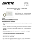
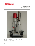
EQUIPMENT Operation Manual Loctite DuraPump Meter Mix System Part Numbers 1041648 1041643 1041641 1041637 1041633 1041647 1041636 1041620 Table of Contents 1 Please Observe the Following 4 1.1 Emphasized Sections 1.2 For Your Safety 1.3 Unpacking and Inspection 1.4 Items Supplied 1.5 Features 1.6 Usage 4 4 4 5 5 5 2 Description 5 3 Technical Data 6 4 Installation 6 5 Operation 7 5.1 Ratio Check Procedure 5.2 Purging the Dispense System 5.3 Machine Cycling 5.4 Connecting a Machine Mounted Valve 5.5 Connecting a Hand Held Valve 5.6 Machine Shut Down 8 9 10 10 11 12 6 Dispense Volume Calculations 12 7 Troubleshooting 13 7.1 Machine is Off-Ratio 7.2 Cycling is too Slow or too Fast 7.3 Pumps are Leaking Material 7.4 Machine will not Cycle 8 Care and Maintenance 8.1 Repairing A Pump 8.2 Replacing Pump Seal 8.3 Mix Block Repair Kit 13 14 14 14 17 17 18 19 9 Accessories and Spare Parts 21 10 Exploded Diagram 22 11 Pneumatic Diagram 31 12 Warranty 32 2 1 Please Observe The Following 1.1 Emphasized Sections Warning! Refers to safety regulations and requires safety measures that protect the operator or other persons from injury or danger to life. Caution! Emphasizes what must be done or avoided so that the unit or other property is not damaged. Notice: Gives recommendations for better handling of the unit during operation or adjustment as well as for service activities. 1.2 For Your Safety For safe and successful operation of the unit, read these instructions completely. If the instructions are not observed, the manufacturer can assume no responsibility. When using tank heaters; continuously monitor the operation until a stable temperature is reached. Do not heat any products beyond 180 F. Do not expose the connecting cable to heat, oil, or sharp edges. Make sure the Unit stands stable and secure. Use only original equipment replacement parts. Do not operate the Unit in excess of 20 cycles per minute. Observe general safety regulations for the handling of chemicals such as Loctite® adhesives and sealants. Observe the manufacturer’s instructions as stated in the Material Safety Data Sheet (MSDS). While under warranty, the unit may be repaired only by an authorized Loctite service representative. 1.3 Unpacking and Inspection Carefully unpack the Loctite® DuraPump and examine the items contained in the carton. Inspect the unit for any damage that might have occurred in transit. If such damage has occurred, notify the carrier immediately. Claims for damage must be made by the consignee to the carrier and should be reported to the manufacturer. 3 1.4 Items supplied 1.5 Features 1.6 Single or Continuous Dispense Mode Footswitch or hand held pneumatic trigger Inlet feed pressure to 1500 PSI Usage 2 Meter-Mix Dispense System Pneumatic footswitch Night cap with nut Ratio cap with nut Sample silicone grease tube Machine manual Use with bulk (non-cartridge packed) 2-part adhesives such as epoxies, urethanes, and acrylics. Description The Loctite® DuraPump Meter Mix System is a bench style, Two-part adhesive dispenser. It can effectively dispense epoxy, urethane, and MMA products. The system is based on Rod metering; whereas, precision rods displace a volume of product during a cycle. A full stroke of the metering rods can yield 28cc (1:1). Depending on the product, dose shots as small as 0.4cc can be achieved. The unit can be connected to receive product from a number of different feed types and can accept pressures up to 1,500 PSI. Use a high viscosity differential dispense valve or mix block where product viscosities are at least six times or more different from each other. High viscosity differentials will likely encounter mixing difficulties. A valve or manifold suited for that type of mixing should be acquired. 4 3 Technical Data Dimensions (L x H x W): 4 Total weight: approx. 12 1/2”W x 15”D X 27”H (approx. 318 mm 381 mm x 686 mm) 85 lbs. Operating voltage: N/A Air Pressure: Dry filtered; 80 –100 PSI Product inlet port: ½”NPT Pneumatic inlet: 1/4”NPT Metered Volume Ratio 1:1 2:1 4:1 10:1 Full Stroke 28 ml 21.7 ml 18 ml 15.6 ml Installation Before using the dispense system for the first time check it carefully for signs of external damage. If any shipping damage is found DO NOT USE THE MACHINE - return it to your supplier immediately. 1. 2. 3. 4. Place the MMD machine on a bench or other stable location appropriate for the dispense system. Ensure the machine is on a sturdy, level surface and can handle the weight and process actions required of the dispense unit. Use the leveling feet of the machine as necessary. Connect a pneumatic supply to the pneumatic inlet fitting at the rear of the machine. Ensure a steady supply of 80 PSI. Connect the footswitch or pneumatic trigger as labeled on the rear panel. A product feed system can be now connected to the unit. Pressure Regulator Air Inlet 5 5 Operation Prepare the machine for use: 1. Use the (optional) product mix-block assembly (1167586) or attach the desired dispense valve (see section 7.1 on off-ratio notes). This manifold is suitable for viscosities of 2,000 cps and higher. Mix Block Assembly Purge Plugs End Cap 2. Connect the feed systems to the MMD machine. 3. Pour or pressurize the products to the MMD machine. Check for any leaks and repair connections if necessary before cycling. Fill the Metering Pump’s grease reservoir to extend the life of the pump seals and maintain an air tight seal. Grease frequently when using filled materials or abrasives. Use a standard grease gun and an inert, silicone, or Loctite Food Grade Grease. 4. Rod Extension Forks are installed on all machines. If product A or B are (sufficiently) pressurized (around 250 PSI or higher, about 125 PSI if MMA seals are used), the ‘Fork’can be removed. This fork is used to pull down the Displacement Rod during a re-charge. Removing the Fork allows the product pressure to extend the ‘metering’rod and thus prevent cavitation or air entrapment (see caution section 7.1). Slide Assembly Displacement Rod Rod Extension Fork Rod Locking Nut Do not allow the machine to cycle dry (without product). Excessive ball valve and or rod seal wear or damage could result. 6 5. Place the machine in Single Dose Mode, and adjust the volume setting for a dispense dose or purge. Have a waste cup ready under the dispense point. Cycle the machine until product begins to come out of the dispense nozzle. 6. Use a flat tip screwdriver to adjust the DISPENSE rate by turning the top flow control on the Main Actuator (CW for slower; CCW for faster); accessible via panel holes on the right side of the machine. If making this adjustment becomes difficult, remove the front panel cover; but, DO NOT cycle the machine unless the ball valve interlock switch is closed (see section 7). Do not allow the machine to recharge at a faster rate than the product can feed into the pumps. Excessive recharge rates could cause air pockets Dispense Speed Fill Speed 9. Adjust the pumps Fill (re-charge) rate by adjusting the bottom flow control on the main actuator (CW for slower; CCW for faster); accessible via panel holes on the right side of the machine. 10. Once the purge procedure is completed, perform a ratio check procedure. 11. If your machine is using the Rod Extension Forks (mentioned in item 4) do not install a static mix nozzle until the ratio is validated. This is to ensure that product is flowing properly into (and out of) the metering pumps. 12. The machine is ready for use. Maintain the adhesive two components separate from each other at all times. Keep the nozzle area clean after each use to prevent curing. 5.1 Ratio Check Procedure This procedure is to ensure that the dispensed volume is at the proper ratio so that when the product goes through the mix nozzle, the adhesive will set and maintain proper bond strength. 7 Ensure that both Part A and B are products are entering the metering pumps. If necessary remove lines or hoses from the DuraPumps’s product outlet ports (or remove mixing valve) and check machine cycling to ensure smooth and even flow of product when the machine is cycled. If the machine is cycling faster than the pumps can be filled, an off-ratio condition will occur. 1. Install a ratio check cap on the dispense nozzle. If your valve type does not permit installing a ratio cap; you may be required to remove the valve and take samples at the end of the lines or hoses. 2. Use two small cups or dishes (one for each part) to capture the dispense volume. Weigh each empty cup and record. 3. Perform a single dose cycle on the MMD machine and capture the dispense amounts on the cups. The dose amount is typically the one used during the production run. 4. Weigh each cup. Calculate the actual weight of the product on the cups. 5. Divide the weight of Part A by the specific gravity of Part A product; do the same for Part B— this is the volume dispense for each. 6. Divide Part A volume by Part B volume— this is your ratio. 5.2 Purging the Dispense System Purging becomes necessary when using the machine for the first time, the dispense path has been disconnected, or air has been introduced into the system. 1. 2. 3. The machine should be ready for normal cycling. Remove the static mix nozzle from the dispense valve. Set the machine to the Continuous Mode. Press the lock button and pull the knob all the way up (without disturbing the locking jam nuts). Pipe Plugs Purge/ dose Control Lock Button 4. Have a waste cup, beaker or pail under the mix-block or dispense valve being used to capture the dispensed product. 8 5. 6. 7. Cycle the machine until an uninterrupted (no air, no burping) flow of product occurs. The purging will vary depending on the application, length of dispense hoses, and the length of product feed lines. Estimate the amount of product purge required according to the manner in which your MMD machine product path is connected. To return to the previous dose size; press the lock button and push the knob all the way down. If an off-ratio condition exists, it may be necessary to purge the mixblock assembly or dispense valve and hoses (if applicable); perform steps (8-11) below. 8. Remove the pipe plugs at the top of each end cap on the mix block assembly (be prepared to capture product (both from the mix-block and from the purge holes at the top of the mix block). Product will drip up and around the end caps. If using a dispense valve, point the valve up so that the trapped air can be released when purging. 9. Reduce the cycle rate of the machine. 10. Cycle the machine until no air bubbles can be seen coming out of the top of the mix block, 11. Re-install the plugs, perform a ratio check and setup the machine for production if the ratio is good. 5.3 Machine Cycling This MMD machine is capable of operating in two (run) modes. 5.4 Single Dose (shot) o A momentary start signal will cause the machine to cycle for the volume of product selected and then re-charge the pumps; ready for the next cycle. The trigger signal must be released before the end of the refill cycle or another cycle will start. Continuous o This mode will cause the machine to cycle for as long as the dispense signal is present. The machine will dispense, recharge, and keep repeating until the start signal is removed. Connecting a Machine Mounted Valve to the DuraPump Ensure that inlet air and product inlet pressures are OFF 1. Remove the mix-block assembly from the machine (if so equipped). 9 2. Attach the required hoses to the valve and to the DuraPump. 3. Remove the remote valve port plugs on the front of the machine. 4. Connect a 5/32 air line from the ‘closed’remote valve port to the closed pneumatic port on the valve. Do the same for the ‘open’port. 5. The remote valve will cycle when the footswitch is actuated. Do not cycle the machine (with product) unless you are sure that the valve is correctly connected. Cycling the machine with reversed air lines on the remote valve can cause damage to the machine or other dispense equipment. 5.5 Connecting a Hand Held Dispense Valve to the DuraPump Ensure that inlet air and product inlet pressure are OFF 1. There are 2 ways of connecting the valve to the machine. First method, perform 5.4 then run 3 lines from the P, A and B connections on the rear of the machine to the handle on the Valve (see handle illustration below). 2. Second method; remove the pneumatic footswitch (and airlines) from the machine. 3. Attach a 5/32”air line to the P port on the rear of the machine and connect to the pilot or constant air to the gun valve (single port side on the hand grip). 4. Connect a Tee fitting at the valve’s OPEN port using a short length of tubing (5/32); then connect another short length of air line from the handle’s A port to this Tee. Connect a long (as needed) air line from the A port (Tee) of the valve to the OPEN (A) port on the machine. 5. Do step 4 above for the CLOSED (B) port. 6. The remote valve will cycle when the trigger is actuated on the remote dispense valve. 10 B; Closed, End Cycle P; Trigger Supply A; Open, Start cycle Do not cycle the machine (with product) unless you are sure that the valve is correctly connected. Cycling the machine with reversed air lines on the remote valve can cause damage to the machine or other dispense equipment. 5.6 Machine Shut Down After the final cycle of the day, de-pressurize the product feed systems and turn off the pneumatic supply. Remove the static mix nozzle and clean the nozzle area. Spread some silicone grease on the night-cap and install on the dispense nozzle. The silicone grease will seal and keep moisture out. The machine will continue to operate without adhesive curing problems so long as the adhesive lines, pumps and dispense points are kept sealed and free of contamination. 6 Dispense Volume Calculations Performance depends on the product being used. Due to the dynamics of products, static nozzle, and application dispense rate, the volume dispense may vary from the programmed amount. When taking volume measurements, ensure that the product has not been idle in the static mix nozzle long enough to affect the viscosity of the material in the mixer. 1. To ensure that the dispensed volume for the application is being met, cycle the machine (at the appropriate dispense volume) a couple of times. 11 2. 3. 4. 5. 7 Have a small dish to capture samples and a grams scale. Cycle the machine and capture the dispense amount on a dish or cup. Weigh the sample and record the measurement; repeat this another 2 times. Obtain the volume by dividing the (dose) weight by the specific gravity of the mixed material. Troubleshooting Before proceeding with any repair, or maintenance operation turn off the air supply to the machine. Ensure that any pressure build-up in the product lines or control system has been relieved. To help with troubleshooting cycling problems, or pump issues, this machine features a maintenance switch that will close the ball valve to the (product) inlet (accessible when the front cover panel is removed— on left side of the machine). This will allow the removal of the pumps without having to disconnect the product feed. The air to the machine can then be turned off for safety (and the ball valve will remain closed to product feed). The valve/switch must be actuated manually— you will immediately notice the ball valve actuator cycle. When the actuator cycles— it is no longer in a dispense mode DO NOT cycle (RUN) the machine when the ball valve is reversed (for maintenance). This kind of work should only be done by qualified personnel that are familiar with and understand the machine’s components and functions. Ball valve interlock switch 7.1 Machine is off-ratio The metering pumps are precision made for the chosen product ratio. Offratio condition is primarily attributed to air in the system. The machine must be purged until air (in the product patch) is removed. On machines that are using Rod Extension Forks (to re-charge the pumps), care must be taken that the recharge is adjusted so that it allows time for product to enter the metering pumps. If the re-charge is too fast, a vacuum 12 can be created each time the machine re-charges; this will cause an off-ratio condition each time the machine cycles— see section 5.1 Off-ratio condition can also occur when part A and part B have viscosities that are at a 6 to 1 or greater difference, and a high viscosity differential mix block manifold (or valve) is not being used. For example, if part A is 75 cps and part B is 800 cps. There is slightly over 10 times the difference in viscosities between the two products. Do not allow the feed system to run low on product or air will be introduced into the system. Another way that the machine could be dispensing ‘off-ratio’is if the machine is leaking product from one or both metering pumps. Inspect the metering pumps and ensure that if there is seepage, that it is not excessive. Excessive leakage is an indication that the seals, the metering rod, or both may require replacing. 7.2 Cycling is too slow or too fast If the machine had been cycling correctly, and suddenly begins to recharge at a faster rate, air is getting into the pumps (this is likely with a pressurized reservoir, for instance). Air is typically introduced through the product feed system. If the machine’s recharge rate begins to decrease, the product viscosity may have increased. The pumps seals could also have reacted with the product and swollen in size causing greater friction between the rod and seals; the seals may need replacement. 7.3 Pumps are leaking material Some amount of leakage from the rods is normal. Most of the product accumulating on the rods is grease (from the grease reservoir). If the leakage is excessive (a large drop forming in less than 1,000 cycles), the seals may be worn. Premature seal wear is typically due to abrasives in the product, foreign particles in the product, or operating the unit with abrasive products (or fillers) and not greasing the reservoir at regular intervals. Pumps will also at the interface (joint between pump tube and seal housing) if the machine was cycled and there was no outlet for the product to escape. This excessive pressure could damage a pump seal and cause leaking. 13 7.4 Machine will not cycle If the machine will not cycle, make sure that the metering rods are fully extended (fill position). The Rod extended position is monitored by pneumatic switches (located under the drip cups); make sure these are closed. Also, the slide assembly Home position pneumatic switch must be closed. Ensure that the pump actuator has ample pneumatic supply. Neither of the main drive (pump) actuator flow controls should be fully closed. Slide Home pneumatic switch (behind plate) Anti-cavitation micro switch If the 3-way ball valve does not actuate, the machine will not cycle. Check the ball valve for air, and that the solenoid is being actuated. 14 Troubleshooting Table Problem Will not start Mode Either Possible Cause Home switch or Rod Home lever switches Action Make sure the lever closes the switch; test with a small flat tip screwdriver or similar device. Single dose Pulse Valve This valve gives a small dose after a cycle-start signal. Test by removing the tubing at the far end of the OUT port of the valve; block the line and actuate a cycle; if no pulse, replace PV-1. R-436 Module After a cycle start, air should be coming out of port 3 of this module; otherwise replace. Mode selector switch Air should come out of this valve when cycled; otherwise replace. R-351 Module Air should come out of port 2 of this module; otherwise replace. Either Will not cycle Continuous Machine does not recharge Either Upper limit switch Ensure the switch is closing; adjust switch lever. Trying to dispense but rods are unable to move upward Either Interlock front panel cover switch Do not operate the machine with the interlock switch actuated; return to normal position before cycling the machine. Ball Valve Actuator The air lines could be reversed. Upper Limit Switch switching problem. Replace the pneumatic switch. Machine is dispensing too rapidly Adjust the dispense flow control. Home switch is stuck closed Adjust or replace the switch. Overshooting the Upper Limit switch Either FOR ANY REPAIRS OR ADJUSTMENTS –OTHER THAN THOSE DETAILED IN THIS MANUAL –PLEASE CONTACT 1-800-LOCTITE (5628483). 15 8 Care and Maintenance In the initial first few weeks of operating the machine, check the drip cups at the end of the metering rods every two days. Clean the cups if necessary. Establish a maintenance schedule (daily, weekly, monthly) depending on observations made during the observation period. When shutting the machine down, remove the static mixer and clean the end of the nozzle with a solvent like IPA. Put a bit of silicon grease on the night cap and install on the nozzle to keep air and moisture out. Keep the dispense nozzle and thread area clean (daily) to prevent adhesive build-up. This is done by wiping the nozzle with clean paper or cloth; with a solvent such as isopropyl alcohol or acetone (do not use acetone on painted surfaces or on plastics or seals). Re-lube the grease reservoir until grease comes out of the reservoir relief port. Typically, a once a week re-lubing will be all that is required. Monitor the metering rods for dryness as an indication that lubing may be necessary (higher cycling rates will dry out the rods sooner). Grease helps to maintain an air tight seal and in keeping the seals from drying out, thus reducing wear due to high friction. Greasing should be conducted more frequently when using filled or abrasive materials. Use a mineral base grease such as Loctite Food Grade Grease (item 51252; 14.5 oz cartridge), or use a silicone base grease for this servicing. 8.1 Replacing a Pump Always wear protective clothing and eye protection when servicing the machine. 1. In Single Dose mode, set a shot about mid-way of full stroke. 2. If the Rod Extension forks are installed, remove the one off of the pump that is to be removed from the machine. 3. Start a cycle; this will leave the rod inserted inside the pump about mid-way (and allow room for the removal of the pump). 4. Make sure product pressure is off and air to the machine has been turned off. Remove the front panel cover of the machine. If the Pump being removed is fed by a gravity tank, actuate the button on the interlock switch (inside the machine; see section 7). This will 16 rotate the 3-way ball valve and prevent the feed tank from emptying out. Once the valve is actuated, air can be removed from the machine. Make sure the pneumatic switch is returned to normal position when servicing is completed. Pump Assembly Pump Tube Grease Fitting Seal Body Assembly Metering Rod Drip Cup 5. Have some wipes (or small cup) ready when the pump is removed to catch oozing (remaining) product in the lines. 6. Use a long handle open-end wrench (1-1/8)”and loosen the compression fitting on the metering pump; pull the pump down and remove from the machine. 7. Place paper or cloth wipes beneath the metering pump to catch any product drip from the bottom of the 3-way ball valve. 8.2 Replacing the Pump Seals Exercise care when removing the seals and seal spacer. Do not score or mar the inside diameter surface of the seal assembly or seal spacer; product leakage will occur. 1. Remove the required pump from the machine. 2. Pull out the metering rod and wipe clean using isopropyl alcohol (a static mix nozzle or similar device can be inserted at the inlet of the pump to help push-out the rod). 3. Remove six hex screws from the bottom of the metering pump. 4. Take the lower part of the pump and clean the adhesive of the top. 5. Remove the static o-ring, and the primary seal. Do not use sharp instruments or tools to remove the seals or spacer. 6. Carefully remove the seal spacer, and then remove the wiper seal. The spacer comes out by tapping the Seal Assembly on a table or 17 carefully tapping the spacer from the backside (grease o-ring side) with a blunt tool-avoid hitting the edges. 7. Installation is in the reverse order. The seal spacer can be cleaned and reused (if not damaged). Static O-Ring Primary Seal Spacer Wiper Seal Seal Body Assembly Grease O-ring Available in Seal Kit items (see section 9 Accessories and Spare Parts) Available in Primary Seal items (see section 9 Accessories and Spare Parts) 8.3 Mix Block Repair Kit The Mix-Block has a spring and ball arrangement that act as a check valve to allow product to move in one direction only— out towards the dispense nozzle. In this manner, product cannot be forced back into the product flow path (towards the pumps). This also prevents one adhesive component from making its way into the other component’s product path. A Teflon seal prevents product leakage at the interface point between the mix-block and the end caps. Ensure that the feed system is depressurized, and that a cycle start cannot be initiated. 18 1. The mix-block seal kit is comprised of two stainless steel balls, two springs and two Teflon seals. 2. Remove three hex screws (of the required side) from the end cap assembly. 3. Remove the ball and spring and insert the new (replacement) set. Replace the Teflon seal on the side of the mix block. 4. Re-install the end cap assembly to the mix-block assembly. 5. Perform a purge to ensure product flow and air removal from the system. Mix Manifold End Cap Spring Seal Ball Available as Mix Block Manifold Seal Kit item # 1069945 19 9 Accessories and Spare Parts Description 9.5 L Gallon Gravity Feed Reservoir Kit Includes Tank, fittings, tubing and mounting hardware 7 L Gallon Nickel Plated Steel Gravity Feed Reservoir Includes: Lid, tubing, and fittings Gravity Tank Stand (for either 9.5 or 7 liter, can hold 2 tanks) Agitator Assembly (electric) Night Cap with Nut Ratio Cap with Nut High Viscosity Differential Valve, General Purpose High Viscosity Differential Valve, MMA Orifice Kit, High Viscosity Differential Valve Precision Flow Rate Controller Disposable Desiccant Breather Mix-block Manifold Seal Kit (includes seals, balls and springs) Mix-Block Manifold (stainless steel) Mix Block Assembly (8901168 complete) 3-Way Ball Valve Repair Kit, for 8901166 3-Way Ball Valve Repair Kit, for 8901587 19.1 mm Seal, Primary, General Purpose 13.5 mm Seal, Primary, General Purpose 9.5 mm Seal, Primary, General Purpose 6.0 mm Seal, Primary, General Purpose Custom, General Purpose Primary Seal (must specify size) 19.1 mm Seal, Primary, MMA 6.0 mm Seal, Primary, MMA Custom, MMA Primary Seal (must specify size) 19.1 mm Seal kit, General Purpose 13.5 mm Seal Kit, General Purpose 9.5 mm Seal Kit, General Purpose 6.0 mm Seal Kit, General Purpose Custom, General Purpose Seal Kit (must specify size) 19.1 mm Seal Kit, MMA 6.0 mm Seal Kit, MMA Custom, MMA Seal Kit (must specify size) 19.1 mm Pump Assembly, General Purpose 13.5 mm Pump Assembly, General Purpose 9.5 mm Pump Assembly, General Purpose 6.0 mm Pump Assembly, General Purpose 19.1 mm Pump Assembly, MMA 6.0 mm Pump Assembly, MMA Custom Pump Assembly, General Purpose (specify ratio) Custom Pump Assembly, MMA (specify ratio) Item Num# 1051660 1051659 1051651 1051655 1053260 1053261 1079254 1079256 1079255 1069695 1051657 1069945 1069947 1167586 1069944 1130327 1061920 1061919 1061918 1061917 1176436 1062436 1061916 1176438 1061915 1061914 1061913 1061913 1176437 1061911 1061900 1180635 1046192 1046191 1046170 1046169 1046161 1046166 1046168 1046165 For parts not listed on this list, please contact 1-800-LOCTITE 20 10 Exploded Diagrams Parts List 8901305 DuraPump Pneumatic Assembly 21 8901305 BOM DuraPump Pneumatic Assembly 22 8901307 Base Assembly 23 8901307 Base Assembly BOM 24 8901306 DuraPump Slide Assembly 25 8901306 DuraPump BOM Slide Assembly 26 8901165 Valve Drive Assembly 27 8901165 Valve Drive Assembly BOM 28 29 11 Pneumatic Diagram 30 31 12 Warranty Henkel expressly warrants that all products referred to in this Instruction Manual for (Henkel DuraPump Meter Mix Dispense Systems) (hereafter called “Products”) shall be free from defects in materials and workmanship. Liability for Henkel shall be limited, as its option, to replacing those Products which are shown to be defective in either materials or workmanship or to credit the purchaser the amount of the purchase price thereof (plus freight and insurance charges paid therefor by the user). The purchaser’s sole and exclusive remedy for breach of warranty shall be such replacement or credit. A claim of defect in materials or workmanship in any Products shall be allowed only when it is submitted in writing within one month after discovery of the defect or after the time the defect should reasonably have been discovered and in any event, within (12) months after the delivery of the Products to the purchaser. This warranty does not apply to perishable items, such as ( fuses, seals, filters, lights, etc.). No such claim shall be allowed in respect of products which have been neglected or improperly stored, transported, handled, installed, connected, operated, used or maintained. In the event of unauthorized modification of the Products including, where products, parts or attachments for use in connection with the Products are available from Henkel, the use of products, parts or attachments which are not manufactured by Henkel, no claim shall be allowed. No Products shall be returned to Henkel for any reason without prior written approval from Henkel. Products shall be returned freight prepaid, in accordance with instructions from Henkel. NO WARRANTY IS EXTENDED TO ANY EQUIPMENT WHICH HAS BEEN ALTERED, MISUSED, NEGLECTED, OR DAMAGED BY ACCIDENT. EXCEPT FOR THE EXPRESS WARRANTY CONTAINED IN THIS SECTION, HENKEL MAKES NO WARRANTY OF ANY KIND WHATSOEVER, EXPRESS OR IMPLIED, WITH RESPECT TO THE PRODUCTS. ALL WARRANTIES OF MERCHANTABILITY, FITNESS FOR A PARTICULAR PURPOSE, AND OTHER WARRANTIES OF WHATEVER KIND (INCLUDING AGAINST PATENT OR TRADEMARK INFRINGEMENT) ARE HEREBY DISCLAIMED BY HENKEL AND WAIVED BY THE PURCHASER. THIS SECTION SETS FORTH EXCLUSIVELY ALL OF LIABILITY FOR HENKEL TO THE PURCHASER IN CONTRACT, IN TORT OR OTHERWISE IN THE EVENT OF DEFECTIVE PRODUCTS. WITHOUT LIMITATION OF THE FOREGOING, TO THE FULLEST EXTENT POSSIBLE UNDER APPLICABLE LAWS, HENKEL EXPRESSLY DISCLAIMS ANY LIABILITY WHATSOEVER FOR ANY DAMAGES INCURRED DIRECTLY OR INDIRECTLY IN CONNECTION WITH THE SALE OR USE OF, OR OTHERWISE IN CONNECTION WITH, THE PRODUCTS, INCLUDING, WITHOUT LIMITATION, LOSS OF PROFITS AND SPECIAL, INDIRECT OR CONSEQUENTIAL DAMAGES, WHETHER CAUSED BY NEGLIGENCE FROM HENKEL OR OTHERWISE. 32 Loctite Industrial Henkel Loctite Corporation One Henkel Way Rocky Hill, CT 06067-3910 Henkel Loctite Corporation 2515 Meadowpine Boulevard Mississauga, Ontario L5N 6C3 Canada Henkel Corporation Automotive / Metals HQ 32100 Stephenson Hwy. Madison Heights, MI 48071 Henkel Ltda. Brazil Av. Prof. Vernon Krieble, 91 06690-11-Itapevi Sao Paulo, Brazil Henkel Capital, S.A. de C.V. Calzada de la Viga, s/n, Fracc. Los Laureles Loc. Tulpetlac, C.P. 55090 Ecatepac de Morelos, Edo de Mexico, Mexico www.loctite.com Loctite is a registered trademark of Henkel Loctite Corporation, U.S.A © Copyright 2003. Henkel Loctite Corporation. All rights reserved. Data in this operation manual is subject to change without notice. Manual P/N: 8901402 Rev F, 04/2013 33