1
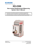
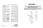
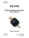
 KDM-8206
Non-Contact Displacement Measuring
System
Rack Reference Manual
1/2 Rack Instrumentation Case (3U/42HP)
3/4 Rack Instrumentation Case (3U/63HP)
Full 19" Sub-Rack (3U/84HP)
Copyright © 2014
PART NO: 860515-001
Last Revised 12/05/14
Kaman Precision Products
A Division of Kaman Aerospace Corporation
217 Smith Street
Middletown, CT 06457
www.kamansensors.com
Table of Contents
PART 1 INTRODUCTION ...............................................................................................4
PART 2 REAR PANEL CONNECTIONS ........................................................................5
PART 3 MEASURING CHANNEL CONNECTIONS .......................................................6
3.1 Back Plane PCB ....................................................................................................6
3.2 Back Panel PCB ....................................................................................................8
PART 4 OPTIONAL DISPLAY MODULE .......................................................................9
PART 5 ENCLOSURES ................................................................................................12
5.1 Full 19" Instrumentation Sub-Rack - 3U/84HP ................................................12
5.2 1/2 Rack Instrumentation Enclosure - 3U/42HP ..............................................16
5.3 3/4 Rack Instrumentation Enclosure - 3U/63HP ..............................................21
PART 6 INTEGRAL POWER SUPPLY ........................................................................25
6.1 Power Supply ......................................................................................................25
6.2 Power Entry Module ..........................................................................................26
APPENDIX A REPLACEMENT OR EXPANSION PARTS .........................................27
www.kamansensors.com
PART NO: 860515-001
Last Revised: 12/05/14
2
Figure 1
Figure 2
Figure 3
Figure 4
Figure 5
Figure 6
Figure 7
Figure 8
Figure 9
Figure 10
Figure 11
Figure 12
Figure 13
Figure 14
Figure 15
Figure 16
Figure 17
Figure 18
Figure 19
Figure 20
Figure 21
Figure 22
List of Figures
Rear Panel I/O ...............................................................................................5
Measuring Channel Back Plane PCB, Front View ........................................6
Measuring Channel Back Plane PCB, Rear View .........................................7
Back Panel PCB ............................................................................................8
Display Module Front Panel ..........................................................................9
Display Module Back Plane PCB, Front View .............................................10
Display Module Back Plane PCB, Rear View ..............................................10
Back Panel P4 Jumper Configuration .........................................................11
Full 19" Sub-Rack Side Outline drawing .....................................................12
Full 19" Sub-Rack Rear / Front Outline drawing .........................................13
Full 19" Sub-Rack Top View Outline Drawing .............................................14
Full 19" Sub-Rack Front/Top with Display ...................................................15
1/2 Rack Front View Outline Drawing .........................................................17
1/2 Rack Rear View Outline Drawing ..........................................................18
1/2 Rack Side/Top View Outline Drawing ...................................................19
1/2 Rack Top View With Display .................................................................20
3/4 Rack Front View Outline Drawing .........................................................21
3/4 Rack Rear View Outline Drawing ..........................................................22
3/4 Rack Side/Top View Outline Drawing ...................................................23
3/4 Rack Top View With Display .................................................................24
Power Supply ..............................................................................................26
Power Entry Module ....................................................................................26
www.kamansensors.com
PART NO: 860515-001
Last Revised: 3/12/2013
3
PART 1 - INTRODUCTION
The KDM-8206 is a modular packaging system for Kaman Precision Products’ line of
inductive displacement transducer electronics. The KDM-8206 enclosures integrate
various measuring channels, power supplies, and displays into a coherent application
specific industrial package. Sensors for the measuring channels are available that
measure displacements in the micro inch/nanometer ranges as well as sensors that can
make accurate displacement measurements at up to 1000oF. The KDM-8206 system is
versatile and flexible. This manual is designed to help put it all together for the specific
system you have purchased.
Features:
•
•
•
•
•
•
•
•
Inductive Sensing Technology
Eurocard/Eurorack packaging
Up to 12 Measuring Channels per rack system
Integral power supply
Single Ended or Differential Output Voltages
4-20mA outputs
Optional Multi-channel display
Optional Multi-rack synchronization
The KDM8206 rack systems are prewired and set up at the factory with all measuring
channels installed. To get started with the 8206 system you will need to:
•
Install the sensors in the application or cal fixture
•
Connect the sensors to the enclosure (see the Back Panel Connections Section)
•
Connect the power cord and turn on the unit
•
If you have a display see the Optional Display Panel Section)
As with any complex electronics system you should thoroughly familiarize yourself with
all the manuals dealing with the product. Refer to these manuals for specific
information. Manuals are available on line @ www.kamansensors.com
WARNING: The integral rack power supply utilizes high voltage (120 or 240 VAC).
Unplug the unit before servicing.
www.kamansensors.com
PART NO: 860515-001
Last Revised: 3/12/2013
4
PART 2 - REAR PANEL CONNECTIONS
Refer to Figure 1 below. Twin BNC connectors on the bottom row are for connecting
the Sensors to the rack or enclosure. The rack was configured at the factory to enable
the measuring channel to use a single coil or dual coil sensor. If a measuring channel is
being changed from a single coil sensor to a dual coil sensor, it will be necessary to add
an additional RF cable between the measuring channel backplane board and backpanel
board.
Measuring channel output voltages are available on two rows of (isolated from chassis)
BNC connectors on the back panel.
•
The upper row (V+) is for single ended outputs.
•
The upper (V+) and lower (V-) are used for differential outputs. The lower (V-)
connectors are present only if differential voltage output is specified at time of
order.
Measuring channel output current (4-20 mA) is also available on the back panel through
a terminal block. The plug in terminal block may be unplugged, connected to customersupplied wire, and plugged back in.
Figure 1 Rear Panel I/O
www.kamansensors.com
PART NO: 860515-001
Last Revised: 3/12/2013
5
PART 3 - MEASURING CHANNEL CONNECTIONS
Internal wiring for each Measuring Channel in a rack or instrument enclosure is in
modular format. Each Measuring Channel requires:
•
•
•
•
A Back Plane PCB to connect to the Measuring Channel
A Back Panel PCB for sensor input and analog voltage or current output
A 6 inch interconnecting ribbon cable between back plane and back panel for
output
Interconnecting 6 inch coaxial cable(s) for sensor input. One cable is required for
a single coil sensor. Two cables are required for a dual coil sensor.
3.1 Back Plane PCB
The Back Plane PCB is installed to the horizontal rails inside the rack and secured with
four screws. A Back Plane PCB is required for each Measuring Channel installed in the
rack. Its purpose is to provide all I/O connections to each Measuring Channel, which
are:
•
•
•
•
•
Sensor connections
Input power
Synchronization signal
Analog output
Optional Display Module input signals
P2 J
2 J
1 Figure 2 Measuring Channel Back Plane PCB, Front View
www.kamansensors.com
PART NO: 860515-001
Last Revised: 3/12/2013
6
P1 P4 P3 JB JA SIN SOUT Figure 3 Measuring Channel Back Plane PCB, Rear View
There are two versions of the Back Plane PCB. The Channel 1 version is installed in
the channel 1 position only. The Channel 1 version is not installed if the rack has a
display module, refer to Part 4 of this manual. The Channel 2+ version is installed for
channel 2 and subsequent measuring channels in the rack. Differences between the
two versions are the connectors installed. Connections to the Back Plane PCB are:
•
•
•
•
•
•
•
•
•
•
J1 Euro connector to Measuring Channel
J2 Connects to subsequent Measuring Channel Back Plane PCB.
JA Sensor input for a single coil sensor. Sensor active coil for a dual coil sensor
JB Sensor inactive coil for a dual coil sensor. Not connected for a single coil
sensor
P1 Input DC power. Only present on channel 1 Back Plane PCB
P2 Connects to previous Measuring Channel Back Plane PCB. Only present on
channel 2+ Back Plane PCB.
P3 Ribbon cable connector. To Back Panel PCB
P4 Dual row terminal strip for optional display module. Refer to Part 4 of this
manual.
SIN Synchronization signal input for optional multi-rack synchronization. Only
present on channel 1 Back Plane PCB
SOUT Synchronization signal output for optional multi-rack synchronization.
Only present on channel 1 Back Plane PCB
www.kamansensors.com
PART NO: 860515-001
Last Revised: 3/12/2013
7
3.2 Back Panel PCB
The Back Panel PCB is installed in the rack just as its name indicates, to the rear panel
of the rack or instrument enclosure. It is secured to the rear panel with three flat head
screws and with the BNC connector nuts. A Back Panel PCB is required for each
Measuring Channel installed in the rack. Its purpose is to provide external I/O
connections for each Measuring Channel and transmit them to the Back Plane PCB. P1 BNC1 BNC2 JA TB1 JB SEN Figure 4 Back Panel PCB
Connections to the Back Panel are:
•
BNC1 Coaxial V+ connector for single ended and differential voltage output.
•
BNC2 Coaxial V- connector for differential voltage output option. Not installed if
this option is not requested.
•
JA Sensor connection to Back Plane PCB for a single coil sensor. Sensor active
coil for a dual coil sensor.
•
JB Sensor inactive coil connection to Back Plane PCB for a dual coil sensor.
Not connected for a single coil sensor.
•
P1 Ribbon cable connector to Back Plane PCB
•
SEN Twin BNC sensor connector.
•
TB1 Two position terminal block for 4-20 mA current output.
www.kamansensors.com
PART NO: 860515-001
Last Revised: 3/12/2013
8
PART 4 – OPTIONAL DISPLAY MODULE
The Display Module provides a convenient method to monitor Measuring Channel
output for Sub-Racks and Instrument Enclosures. The Display Module is a two slot
wide panel with an LED display and selector switch. It can display output of a single
Measuring Channel in the rack at a time. The Display Module must be installed in slots
1 and 2 of a rack or instrument enclosure.
The Display Module includes:
•
•
•
a front panel with a 4-½ Digit ±10VDC LED display, a switchboard with a 10position switch
a back plane PCB for DC power and Measuring Channel input
A ribbon cable connection between front panel and back plane PCB
The Displayed output is the single ended voltage (the difference between V+ and
Ground) of the Measuring Channel selected. For the meter to display differential output
(the difference between V+ and V- Outputs), jumper J7 on the KDM-8206 Measuring
Channel must be changed from positions 1 and 2 to positions 2 and 3 . (Reference the
KDM-8206 System User’s Manual)
Figure 5 Display Module Front Panel www.kamansensors.com
PART NO: 860515-001
Last Revised: 3/12/2013
9
J1 P3 Figure 6 Display Module Back Plane PCB, Front View
P1 Figure 7 Display Module Back Plane PCB, Rear View
www.kamansensors.com
PART NO: 860515-001
Last Revised: 3/12/2013
10
For Figures 6 and 7 above, the connections labeled are:
•
J1 connects to the back plane PCB of Measuring Channel No. 1
•
P1 input DC power from rack power supply
•
P3 ribbon cable connection to the front panel display module
To configure the rack enclosure for the Display Module, jumpers need to be set on
terminal strip P4 on the Back Panel PCB of each Measuring Channel. Placement of
jumpers determines the channel on the Display Module where output from that
Measuring Channel is displayed.
The top two rows of P4 are for Channel 1 on the Display Module and are labeled V1+
and V1-. When jumpers are placed on P4 connecting pins A and B of that of the V1+
and V1- rows, output is routed to the Channel 1 (switch) position on the Display Module.
Rows 3 and 4 (V2+ and V2-) are for Channel 2. Rows 5 and 6 (V3+ and V3-) are for
Channel 3. And so on through V10+ and V10- for Channel 10.
Channel 1 is the Measuring Channel adjacent to the Display Module and channels are
numbered in sequence from left to right when viewed from the front of the rack or
instrument enclosure.
Figure 8 Back Panel P4 Jumper Configuration
Figure 8 is a depiction of P4. The left side is a top view showing the row labels. The
right side of Figure 8 shows P4 with jumpers installed for Measuring Channel 1.
www.kamansensors.com
PART NO: 860515-001
Last Revised: 3/12/2013
11
PART 5 - ENCLOSURES
Kaman Precision Products provides three different enclosures for the KDM-8206
Measuring Channels.
5.1 Full 19" Instrumentation Sub-Rack - 3U/84HP
The sub-Rack is a 19" wide frame having solid side panels and horizontal rails across
the top and bottom to hold the Measuring Channels in place. Use of a sub-Rack
enables installation of the KDM-8206 system into a standard 19" test equipment rack.
The sub-Rack normally includes a built in 120VAC/240VAC power supply to provide
±15VDC required by the Measuring Channels. It also can be configured with a display
module that has up to ten selectable inputs.
Part Number Configuration
855859-0XX No display module, 12 available positions
855859-1XX One display module, 10 available positions
855859-2XX No display module, rack to rack Synchronization, 12 available
positions
855859-3XX One display module, rack to rack Synchronization, 10 available
positions
Figure 9 Full 19" Sub-Rack Side Outline drawing
www.kamansensors.com
PART NO: 860515-001
Last Revised: 3/12/2013
12
Figure 10 Full 19" Sub-Rack Rear / Front Outline drawing
www.kamansensors.com
PART NO: 860515-001
Last Revised: 3/12/2013
13
Figure 11 Full 19" Sub-Rack Top View Outline Drawing
www.kamansensors.com
PART NO: 860515-001
Last Revised: 3/12/2013
14
Figure 12 Full 19" Sub-Rack Front/Top with Display
www.kamansensors.com
PART NO: 860515-001
Last Revised: 3/12/2013
15
5.2 1/2 Rack Instrumentation Enclosure - 3U/42HP
The 1/2 rack instrument case is a fully enclosed stand-alone enclosure for the KDM8206 system with a tilt bar to elevate the front of the case. The instrument case has an
integral 120VAC/240VAC power supply to provide ±15VDC required by the Measuring
Channels.
The instrument case also can be configured with a display module with selectable
inputs.
Part Number Configuration
855861-0XX No display module, 6 available positions
855861-1XX One display module, 4 available positions
www.kamansensors.com
PART NO: 860515-001
Last Revised: 3/12/2013
16
Figure 13 1/2 Rack Front View Outline Drawing
www.kamansensors.com
PART NO: 860515-001
Last Revised: 3/12/2013
17
Figure 14 1/2 Rack Rear View Outline Drawing
www.kamansensors.com
PART NO: 860515-001
Last Revised: 3/12/2013
18
Figure 15 1/2 Rack Side/Top View Outline Drawing
www.kamansensors.com
PART NO: 860515-001
Last Revised: 3/12/2013
19
Figure 16 1/2 Rack Top View With Display
www.kamansensors.com
PART NO: 860515-001
Last Revised: 3/12/2013
20
5.3 3/4 Rack Instrumentation Enclosure - 3U/63HP
The 3/4 rack instrument case is a fully enclosed stand-alone enclosure for the KDM8206 system with a tilt bar to elevate the front of the case. The instrument case has an
integral 120VAC/240VAC power supply to provide ±15VDC required by the Measuring
Channels.
The instrument case also can be configured with a display module with selectable
inputs.
Part Number Configuration
855860-0XX No display meter, 9 available positions
855860-1XX One display meter, 7 available positions
Figure 17 3/4 Rack Front View Outline Drawing
www.kamansensors.com
PART NO: 860515-001
Last Revised: 3/12/2013
21
Figure 18 3/4 Rack Rear View Outline Drawing
www.kamansensors.com
PART NO: 860515-001
Last Revised: 3/12/2013
22
Figure 19 3/4 Rack Side/Top View Outline Drawing
www.kamansensors.com
PART NO: 860515-001
Last Revised: 3/12/2013
23
Figure 20 3/4 Rack Top View With Display
www.kamansensors.com
PART NO: 860515-001
Last Revised: 3/12/2013
24
PART 6 - INTEGRAL POWER SUPPLY
WARNING: The integral power supply utilizes high voltage
(100 to 240VAC). Unplug the unit before servicing.
6.1 Power Supply
The power supply for the KDM-8206 rack enclosures is integral to the chassis and
mounted internally on the side panel. The KDM-8206 power supply provides a ±
15VDC regulated output. The same power supply is utilized for the Full 19” Sub-Rack,
the 1/2 Rack Instrument Enclosure, and the 3/4 Rack Instrument Enclosure. It has
capacity to power 1 to 12 Measuring Channels, or the Optional Display Module and 1 to
10 Measuring Channels. Power supply specifications are:
Input Power:
100VAC ±10% to 240VAC ±10%, 50/60 Hz, 76 VA
Output Power:
+15VDC ± 0.5V @ 1A (Peak Load 1.5A)
-15VDC ± 0.5V @ 0.67A (Peak Load 1A)
No modifications are required to operate the KDM-8206 Sub-Racks or Instrument
enclosures for input voltages between 100 and 240VAC.
DC power is distributed from the power supply via a 4 pin connector to the Channel 1
back plane PCB in the first slot. The back plane has a mating connector and can be
either a Measuring Channel back plane PCB or a Display Meter back plane PCB. It is
then distributed to all channels in the rack via interconnecting back plane PCB
connectors for the Measuring Channels.
The power supply is a unique design to provide specific voltages and currents required
for the Measuring Channels. It is physically configured to mount on the side rail of the
Instrument Enclosures and Sub-Rack.
For Figure 21 below, Power Supply connections labeled are:
•
J1 DC output to Back Plane PCB of Measuring Channel No. 1
•
G1 Input ground from Power Entry Module
•
G2 Chassis ground
•
G3 Chassis ground
•
L
•
N Neutral AC input from Power Entry Module
Line AC input from Power Entry Module
www.kamansensors.com
PART NO: 860515-001
Last Revised: 3/12/2013
25
G2 L J1 N G3 G1 Figure 21 Power Supply
6.2 Power Entry Module
The power entry module provides an on/off switch and a fuse receptacle. If it becomes
necessary to replace the fuses refer to Appendix A for the replacement part number.
Use a small flat tip screwdriver or suitable instrument to pry the fuse receptacle out of
the power entry module when replacing the fuses.
Figure 22 Power Entry Module
www.kamansensors.com
PART NO: 860515-001
Last Revised: 3/12/2013
26
APPENDIX A
REPLACEMENT OR EXPANSION PARTS
Kaman P/N
827286-022G
816619-100G
816620-100G
827322-006G
827325-G2406G
855852-001G
855853-001G
855854-100G
855858-000G
Description
FUSE 2.5A 250V T-LAG 5 X 20 MM
ASSEMBLY PANEL BLANK FRONT 7HP
KIT PANEL BLANK REAR
CABLE, RF SMA M/M 6 INCH
CABLE, RIBBON 28 AWG 24 COND 6 INCH
BACK PLANE PCB CH 2+
BACK PANEL PCB (W/O DIFFERENTIAL)
KIT MODULAR POWER SUPPLY 8206
KIT MODULAR DISPLAY MODULE 8206
www.kamansensors.com
PART NO: 860515-001
Last Revised: 3/12/2013
27