1
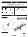
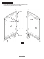
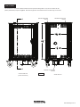
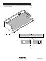
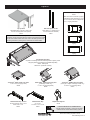
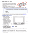
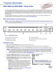
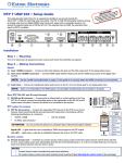
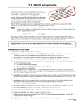
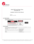
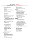
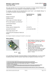
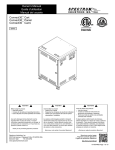
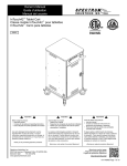
Owner’s Manual
Compact Presentation Lectern
55218
Standard CPL
55223
with Overbridge Control Console
™
CPL with Overbridge Control Console
& Balloon Wheels
55223BW
shown with optional
insert panel (shaded)
Standard CPL
with Balloon Wheels
55218BW
CAUTION:
Before using this product, read this manual and follow
all safety and operating instructions.
Before you begin, please make sure all parts and
proper quantities are included. Any parts damaged
during shipment must be reported within 15 days of
receipt. To report information regarding damages or if
you have any questions, please call 1-800-235-1262.
To purchase parts or accessories, please contact us at
www.spectrumfurniture.com
1-800-235-1262
Thank you for purchasing Spectrum products!
Spectrum Industries, Inc
Chippewa Falls, WI 54729, USA
058719R8 Page 1 of 10
Safety
• Read this owner’s manual before assembly or operation.
• Do not allow children to move lectern.
• Move slowly and carefully when mobile.
• For indoor use only. Do not install or store the unit where it will be exposed to weather. Keep unit dry.
• For added safety, plug the unit into a grounded three-prong receptacle controlled by a GFI
(Ground Fault Interrupter) circuit breaker.
Hardware Package Contents
(1) 052577B
Handle Gusset
(10) 052605
1/4-20 x 15mm JC bolts
(2) 055001
Handle mount
Tools Required
(10) 052605
1/4-20 x 15mm JC bolts
(8) 035252
3/16” x 1/2” pine tree button
7/16” or adjustable wrench
4mm hex wrench
(included)
(1) 025039
4mm hex wrench
Assembly / Setup
Handle Assembly
1. Attach the handle gusset and handle mounts to the bottom of the handle using 1/420 x 15mm JC Bolts as shown in Figure 1. Do not tighten bolts completely yet.
handle
Note: Handle is not included with the toe kick version.
Skip to step 3 if you have a CPL with a toe kick.
Note: It is critical that all joint connectors are used in
the attachment of the handle.
1/4-20 x 15mm
JC bolt
handle mount
1/4-20 x 15mm
JC bolt
1/4-20 x 15mm
JC bolt
handle gusset
1/4-20 x 15mm
JC bolt
handle mount
Figure 1
1/4-20 x 15mm
JC bolt
Handle Installation
1. Determine which side of the lectern you would like the handle to be mounted, and open both doors.
2. Attach the handle assembly to the side of the lectern with (4) 1/4-20 x 15mm JC bolts. As shown in Figure 2.
3. Tighten all bolts securely.
Figure 2
058719R8 Page 2 of 10
Hole Plug Installation
1. If one side of the unit will not have a handle or flip-up document camera shelf attached, install
pine tree buttons in the unused mounting holes as shown. Figure 3.
2. Install 1/4” hole plugs and pine tree buttons in the remaining open holes as shown.
1/4” hole plugs
handle
pine tree buttons
corner column
1/4” hole plugs
pine tree button
pine tree button
Figure 3
058719R8 Page 3 of 10
Floor Anchoring (Toe Kick models only)
1. If your CPL is equipped with a toe-kick, and you wish to attach it to the floor, the toe-kick will need to be detached
from the unit. To detach, remove the (4) 1/4-20 x 40mm JC bolts (one on each corner) from inside the cart.
2. Carefully lift the lectern off the toe-kick. This will require several people. Figure 4.
3. Locate the toe-kick into its final position on the floor and mark the (4) mounting hole locations on the floor (The
toe-kick mounting holes are approximately 1/2” dia.)
4. Drill holes into the floor and anchor the toe-kick with appropriate fasteners.
5. Carefully lift the lectern back onto the toe-kick and align the (4) mounting holes.
6. Re-attach the lectern to the toe-kick with the previously removed JC bolts.
CPL
1/4-20 x 15mm JC bolt
(4 req’d)
Note: 4 fasteners are required
to anchor toe kick to floor.
(fasteners not included).
toe kick
Figure 4
058719R8 Page 4 of 10
Rack Rails
The standard CPL comes with rack rails mounted in the front (instructor-side) position. They can be moved to the rear
position (student-side) if required. Figure 5. Rack-mount equipment can be fastened to the rack rails using 10-32 screws.
A
optional student-side
rack rail
A
instructor-side view
(shown without door)
standard instructor-side
rack rail
standard 15’ retractable
cord reel
Figure 5
section view A-A
058719R8 Page 5 of 10
Overbridge insert panel removal (overbridge models only)
1. To remove the insert panel, remove the (2) 1/4-20 x 35mm JC bolts with a 4mm hex wrench. Figure 6A.
2. Lift the panel out. Figure 6B.
Figure 6A
Note: The insert panel shown (shaded) is not included with the lectern or overbridge.
This option needs to be ordered separately to complete the overbridge. This insert
panel is symmetrical and can be easily removed, rotated, and re-installed if a cutout
needs to be relocated to the opposite side of the overbridge.
Figure 6B
058719R8 Page 6 of 10
Cord reel operation
Operating Instructions:
1. To latch cord - Pull cord out to full length. Allow the cord to retract 1-2 feet back into
the reel. Pull the cord out slowly. When a ‘click’ is heard, the cord will latch in place.
2. Plug into 110-125V (single phase), 3-conductor wall outlet.
3. To release cord - Unplug from wall outlet. Pull cord out slowly until clicking stops.
The latch will release and the cord can be guided back into the reel. Do not allow the
cord to fly unrestricted back into the reel.
4. Do not overload or circuit breaker (15-amp maximum) will cut off current. To restore
power, remove overload, wait two minutes, then reset the circuit breaker by pressing
the button on the back of the 3-prong male power plug.
Maintenance:
1. Remove dirt and grime as soon as it accumulates on the reel case by using a soft,
damp cloth (a mild detergent may be used if needed), being careful not to wet
the electrical plug. Never immerse any part of the unit in any solution to clean.
DO NOT use solvents such as gasoline, turpentine, etc. to clean unit.
2. Keep cord clean to assure smoothest automatic retraction. Simply pull cord to its
full length and allow to retract through a dampened rag. Pull out full length again
and sprinkle cord with talcum powder.
Specifications:
reset button
15’ retractable, 15-amp, 125V, 12 AWG with breaker, UL Listed
WARNING
• This cord reel is intended for general indoor use only. It is not intended to be used
in potentially dangerous locations such as flammable or explosive atmospheres.
The reel is not waterproof and not intended for use in potentially wet locations.
• Do not overload (15-amp maximum).
power plug
Moving the lectern
1.
2.
3.
4.
Before moving the unit, unplug all power cords and retract power cord into the reel (if equipped).
Be sure the casters are in the unlocked position and the doors closed.
Move the lectern slowly and carefully.
Lock the casters after moving.
058719R8 Page 7 of 10
Options
®
Extron Controller Adapter Kit
55239
Note: This kit is for use with a 5-gang
overbridge cutout measuring 97⁄16”W x
315⁄16”D. The kit can be configured for
2, 3, or 4-gang controllers.
Flip-up Shelf
adjustable-height, mounts on left or right
183⁄8”W x 221⁄8”D (50 lbs max capacity)
55219
Rear rack rail kit for CPL
adds 16RU (173⁄8” between front
and rear rails when installed)
55221
2-gang
Note: Power & communication wiring for document cameras, laptop
computers, and/or projectors placed on the flip-up shelf should be routed
on top of the audience-side of the shelf. Use of the shelf grommet hole
for wiring will result in pinching of the cords when the shelf is folded.
3-gang
4-gang
Overbridge Insert Panel
required for overbridge version-contact Spectrum to specify cutout
size(s) & position(s)-overbridge not available separately
96501 - blank panel
96501mod - panel with cutout(s)
™
TouchLink 350CV cutout cover plate
71⁄2”W x 61⁄4”D (16-gauge steel)
55350
7-Outlet Power Strip, insured
w/ surge protector, and 12’ cord
10”W x 2”D x 11⁄8”H
99024
™
Cable Cubby 300S cutout cover plate
(overbridge models only)
511⁄16”W x 7”D (20-gauge steel)
96500
6-Outlet Power Strip
w/ 12’ cord
115⁄16”W x 11⁄16”D x 13⁄16”H
99023
™
TouchLink 700MV cutout cover plate
™
(TouchLink 700MV overbridge models only)
3
9 ⁄8”W x 67⁄16”D (16-gauge steel)
55351
Replacement Key Set
55142
Flat Panel Monitor Arms & Tablet Mounts
(See the Spectrum website or catalog for the latest
available monitor arm & tablet mounting options)
Worksurface drilling required to mount
058719R8 Page 8 of 10
Rack-mount accessories
Note: Rack-mount accessories with a depth
greater than 189⁄16”D will not fit in the CPL.
Check the dimensions of all equipment before
installation. The following Spectrum rackmount accessories will not fit the CPL:
97517 - LT-4 Laptop Storage Unit
97503 - Pull-out Shelf (3RU)
Cantilever Shelf (2RU)
171⁄2”W x 18”D x 31⁄2”H
(50 lbs max load)
97504
Locking Drawer (2RU)
interior dims:
153⁄4”W x 1311⁄16”D x 27⁄8”H
(25 lbs max load)
97514
Cooling Fans (3RU)
19”W x 2”D x 51⁄4”H
Single Fan-97507
Double Fan-97506
Cantilever Shelf (3RU)
171⁄2”W x 18”D x 51⁄4”H
(80 lbs max load)
97502
Drawer (3RU)
interior dims:
1515⁄16”W x 141⁄2”D x 51⁄4”H
(50 lbs max load)
97518
Wire Lace Kit
3 lace straps included
95517
Pull-Out Shelf (2RU)
161⁄2”W x 173⁄4”D
(50 lbs max load)
97505
Drawer (4RU)
interior dims:
1515⁄16”W x 141⁄2”D x 7”H
(50 lbs max load)
97519
9-Outlet Power Strip
(1RU)
19”W x 9”D x 13⁄4”H
99021
Flexible Halogen Light
(1RU)
19”W x 2”D x 13⁄4”H
99033
Locking File Drawer (8RU)
w/ file holder
interior dims:
153⁄4”W x 139⁄16”D x 135⁄16”H
(50 lbs max load)
97515
Rack-Mount Blanks
(fills rack spaces where
components are not needed)
97516 - (1⁄2 RU)
97510 - (1RU)
97511 - (2RU)
97512 - (3RU)
97513 - (4RU)
058719R8 Page 9 of 10
Warranty
WE WILL MAKE IT RIGHT FOR YOU!
Spectrum is committed to provide complete customer satisfaction. Each of our products are manufactured from the best materials available and each
product is stringently monitored throughout the production process through our P.A.C.E. program (Product Assurance to meet Customer Expectations).
Our Customer Service Help Line 1-800-235-1262 is ready to provide immediate attention to any questions, comments or concerns. We are available
to answer your calls Monday through Friday from 7 am to 5 pm CST, excluding observed holidays. In addition your product comments or concerns are
welcome via e-mail at: [email protected].
Warranty Statement
We guarantee all Spectrum products to be free of all defects in materials and workmanship, for the original owner, for a period of ten years. Any item
deemed defective by Spectrum or the original manufacturer, under normal use conditions, will be repaired or replaced at Spectrum’s discretion. This
warranty applies to all products manufactured and distributed by Spectrum except the products
listed below.
Items that have a varying warranty include, but are not limited to, the following:
• Adjustable Crank/Electric Desk Legs (1 yr)
• Flat Panel Desk Gas Cylinders (1 yr)
• Upholstered Soft-Goods (5 yrs)
• Adjustable Height & Stacking Chair Parts – including frames, gas cylinders, wood and plastic parts, and control handles (7 yrs)
• Adjustable Height & Stacking Chair Casters (2 yrs)
• Chair Upholstery & Textiles (2 yrs of normal use of Soft Goods, Adjustable Height, Stacking, Wood and Metal Chairs)
• Chair Upholstery - Graded-In Fabrics and C.O.M (no warranty)
• Height Adjustable Columns and Lifts (1 yr)
• General Use Casters (1 yr)
• Electrical – Electri-Pak, Power Communication Modules, and special order ECA electrical items (1 yr)
• Electrical - Power Strips & Electrical Timers (1 yr)
• Electrical Surge Suppressors (lifetime)
• Electrical - Retractable Power Cords (1 yr)
• Keyboard/Mouse Trays (1 yr)
• Flat Panel Monitor Arm – General Parts (5 yrs)
• Flat Panel Monitor Arm – Gas Cylinders (2 yrs)
• CRT Monitor Arm (1 yr)
Warranty is void if product is not used for its intended purpose or subjected to an unusual application, multiple-shift use, alteration, accident, abuse or
abnormal wear and tear. Representations of colors on-line and in printed materials are meant to be a close reference to the actual colors but not an
exact match. Slight variations in color and texture of wood stains, powder coating, laminates, fabrics and other materials are normal in different manufacturing lots; as such these variations are not considered defects.
DESIGNED FOR INDOOR USE ONLY – Unless specifically stated in the product specifications, Spectrum’s products have been designed and constructed for indoor use only. Moving or using outdoors, or on excessively rough surfaces, may cause damage to the products and will void the warranty.
If an outdoor application is desired please contact us to discuss potential custom design solutions.
The warranty, as stated above, supersedes any previous warranties and is effective as of 9/1/2010
925 First Avenue, PO Box 400, Chippewa Falls, WI 54729
E-mail: [email protected]
Ph: 1-800-235-1262
Fax: 1-800-335-0473
web: www.spectrumfurniture.com
058719R8 Page 10 of 10