1
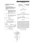
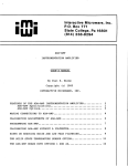
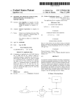
US007043691B1
(12) Ulllted States Patent
(10) Patent N0.:
Kwon et al.
(54)
(75)
US 7,043,691 B1
(45) Date of Patent:
May 9, 2006
METHOD AND APPARATUS FOR ASSISTING
5,995,933 A *
A USER TO MAKE A CONNECTION
BETWEENA MAIN DEVICE AND A
6,131,111 A * 10/2000 Yoshino et a1.
6,263,499 B1 * 7/2001 Nakamura et a1.
PERIPHERAL DEVICE
6,417,869 B1*
6,459,961 B1*
Inventors: [1 Gun KWon, Seoul (KR); Ji Yeon
.
7/2002
10/2002
709/204
717/171
D0 .................... ..
345/718
Obradovich et a1. ......... .. 701/1
FOREIGN PATENT DOCUMENTS
HWang, Seoul (KR)
'
11/1999 Fado et a1. ............... .. 704/270
-
DE
195 24 919 A1
1/1997
DE
692 14 585 T2
2/1997
(73)
Assignee. LG Electronics Inc., Seoul (KR)
DE
(*)
Notice:
* Cited by examiner
Subject to any disclaimer, the term of this
patent is extended or adjusted under 35
[ISO 154(1)) by 353 days_
196 04 647 Al
3/l997
Primary ExamineriKristine Kincaid
Assistant ExamineriPeng Ke
(21) Appl. No.: 09/608,434
(22) Filed:
(74) Attorney, Agent, or FirmiBirch, Stewart, Kolasch &
Birch, LLP
Jun. 30, 2000
(57)
(30)
ABSTRACT
Foreign Application Priority Data
Dec. 7, 1999
(KR)
............................. .. 1999/55490
Amethod and apparatus are provided for assisting a user to
make a connection betWeen a main device and peripheral
(51)
Int. Cl.
.
G06F 3/00
US.
Cl-
(200601)
.
.
.
nect one or more peripheral devices to the main device is
. . . . . . . . . . . . . . . . . . . . ..
_
(58)
.
dev1ce. An illustration visually demonstrating hoW to con
_
On
_
’
a
Screen‘
In
one
embodiment’
the
illustration shoWs at least one connecting portion of the main
Field of Classi?cation Search .............. .. 345/705,
device, the Connecting portion of at least one peripheral
345/706,
708, 709, 714, 715, 717,_ 718, 731
_
See application ?le for complete search history.
device, and the connection betWeen the connecting portion
_
of the main device and the connecting portion of the
peripheral device. In another embodiment, more than one or
(56)
References Cited
us PATENT DOCUMENTS
all of the connecting portions of the main device are shown.
Alternatively, the connecting portions of a plurality of a
peripheral devices are shoWn.
5,680,323 A *
10/1997
Barnard .................... .. 345/720
5,828,834
10/1998
Choi
A
*
5,903,266 A *
. ... ... ... .
. . . ..
713/202
5/1999 Berstis et a1. ............. .. 345/708
ANTENNA
CABLE TV
WALL JACK ANTENNA LOOPANTENNA
CABLE2 0UT CABLEI
28 Claims, 7 Drawing Sheets
TV Rear Panel
7’
'9
s-vmroQ
IN
Y AUDIO
IN
QPB @L
DVD/HI RES
COMP IN
439 DT"_ RF
DB5
VGA
t 20
CALIBRATION
ZZ /
Cable TV Box
@L
HD DBS AUDIO VAR-—A G~
IN/VGA IN
OUT LINK
DVD-Player
oooooo
0
00©ooo
IN
OUT
IN OUT
L
OIN QIN °0UT
DVD HD DES Dig AUDIO
H1 RES VGA
our
VCR
0
I LLf
(D
—DOLBY Digital
ANT INPUT
HD~
CENTER MODE
IN
Q
S-VIDEO
Z4
D-OUT
Lay
HD-DBS
090
D-OUT
VGA OUT kSo
32
C) 0 Move @1 Back
U.S. Patent
May 9, 2006
Sheet 2 0f 7
US 7,043,691 B1
FIG. 2
set up/
//
@
§
/
screen source
/EZ hook-up /
EZ Program
EZ scan
Vldeo
DTV ANT tune
audio
CH addition/erasure /
.
special
CH label
surfing
DVCR mode
time
EZ focus
guide plus+
B
lock
4,39’- L/o
EZ demo
.419}
L ,2
L/ 4
US 7,043,691 B1
1
2
METHOD AND APPARATUS FOR ASSISTING
A USER TO MAKE A CONNECTION
BETWEEN A MAIN DEVICE AND A
PERIPHERAL DEVICE
embodiment, the connecting portion of a plurality of a
peripheral devices are shoWn in the illustration.
In another embodiment of the present invention, the
illustration shoWs at least one connecting portion of the main
device, and the connections to make to the connecting
portion of the main device When connecting a particular
BACKGROUND OF THE INVENTION
peripheral device. Again, more than one or all of the
connecting portions of the main device may be illustrated.
With respect to both the ?rst and second embodiments,
1. Field of the Invention
The present invention relates to a method and apparatus
for guiding connections betWeen a main device and external
and the alternatives thereof, a menu screen is preferably
displayed. The menu screen provides as menu items, the
peripheral devices.
peripheral devices or combinations of peripheral devices
2. Background of the Related Art
Connections betWeen a display device and peripheral
devices in the related art have mostly been betWeen a TV
receiver and a Video Cassette Recorder (VCR). In such
cases, the connection betWeen the TV receiver and the VCR
is through a RF output terminal on the VCR and a RF input
terminal on the TV receiver, or through a composite video
and audio L/R using an external input terminal, ie a RCA
type jack. Although the connection seems simple, to actually
20
Which can be connected to the main device. A user, through
an input device, selects one of the menu items, and based on
the menu item selected, the illustration is changed to shoW
the connections betWeen the main device and selected
peripheral device or devices.
The main device may be any device to Which a plurality
of peripheral devices can be connected, such as a TV
receiver and a personal computer. The peripheral devices are
connect or reconnect a TV receiver and a VCR, users
the peripheral devices associated With the main device. In
frequently refer to a manual. Thus, if the manual is lost, a
user may experience dif?culty in making even a simple
connection.
the case of a TV receiver, the peripheral devices include a
VCR, a DVD player, an antenna, a cable box, a digital
Also, connections to a TV receiver may become more
complicated as there are other peripheral devices for con
necting to the TV receiver such as a cable box, a Digital
25
a connection betWeen the main device and a peripheral
device according to the present invention provide the advan
tages of a user-friendly guide for making such connections
Versatile Disk (DVD), a digital terrestrial broadcast receiver,
a satellite set top box, and PC. Moreover, due to a recent
increase in the functions of a TV, even more peripheral
television receiver, etc.
The method and apparatus for assisting the user to make
Without having to resort to a user’s manual. Thus, the present
30
devices may need to be connected. Thus, if the number of
invention solves the problems and disadvantages discussed
above With respect to the related art.
peripheral devices keeps increasing, users Will experience
more dif?culty in connecting a TV receiver to peripheral
devices and in order to explain such connections, a user’s
manual Will also become more complicated.
As an alternative to making connections by referring to a
BRIEF DESCRIPTION OF THE DRAWINGS
35
The invention Will be described in detail With reference to
the folloWing draWings in Which like reference numerals
provides a questionnaire regarding What type of peripheral
refer to like elements Wherein:
FIG. 1 is a block diagram of a TV receiver in accordance
device needs to be connected and displays the necessary
With a preferred embodiment of the present invention;
user’ s manual, an initial setup menu in the related art of a TV
FIG. 2 is a process for selecting an EZ hook up menu in
circuit to a user based upon the ansWers to the questionnaire. 40
accordance With a preferred embodiment of the present
Thus, a user can connect a peripheral device to the TV
receiver according to the circuit shoWn on the TV screen.
invention;
HoWever, the questionnaires are often complicated and if a
FIG. 3 is a Wiring diagram shoWing connections betWeen
user Wishes to see a connection to a peripheral device other
a TV receiver and peripheral devices When a cursor is
positioned at Ant/Cable item in an EZ hook up menu in
than the one selected, the user can only see the circuit after
45
completing the questionnaire for the selected peripheral
accordance With a preferred embodiment of the present
device. Thus, a user cannot see the overall connection or
invention;
Wiring at a glance. Particularly, When a user merely Wishes
FIG. 4 is a Wiring diagram shoWing connections betWeen
to understand hoW a TV receiver and peripheral devices are
a TV receiver and peripheral devices When a cursor is
positioned at an Ant/Cable and VCR item in an EZ hook up
connected, the method in the related art is complicated and
50
items in accordance With a preferred embodiment of the
inconvenient to the user.
present invention;
FIG. 5 is a Wiring diagram shoWing connections betWeen
SUMMARY OF THE INVENTION
In the method and apparatus for assisting a user to make
a connection betWeen a main device and peripheral device,
an illustration visually demonstrating hoW to connect a
peripheral device or combination of peripheral devices to the
main device is displayed on the display screen. More spe
ci?cally, in one embodiment, the illustration shoWs at least
55
a TV receiver and peripheral devices When a cursor is
positioned at a Cable Box and VCR item in an EZ hook up
menu in accordance With a preferred embodiment of the
present invention;
FIG. 6 is a Wiring diagram shoWing connections betWeen
60
a TV receiver and peripheral devices When a cursor is
positioned at a DVD/Hi Res item in an EZ hook up menu in
one connecting portion of the main device, the connecting
accordance With a preferred embodiment of the present
portion of at least one peripheral device, and the connection
betWeen the connecting portion of the main device and the
connecting portion of the peripheral device or devices. In an
invention; and
alternative embodiment, more than one or all of the con
necting portions of the main device are shoWn in the
illustration. In addition to or instead of the alternative
FIG. 7 is a Wiring diagram shoWing connections betWeen
65
a TV receiver and peripheral devices When a cursor is
positioned at a DVD/Hi Res item in an EZ hook up menu in
accordance With another embodiment of the present inven
tion.
US 7,043,691 B1
4
3
DETAILED DESCRIPTION OF THE
PREFERRED EMBODIMENT
Similarly, if the user selects DVD, a DVD (YCbCr) video
signal received through the DVD input terminal J5 Would
begin to be displayed on the TV screen. If a different
Reference Will noW be made in detail to the preferred
peripheral device is selected by a user, a video signal of the
embodiments of the present invention, examples of Which
corresponding peripheral device Would begin to be dis
are illustrated in the accompanying drawings. FIG. 1 is a
block diagram of a TV receiver in accordance With a
played on the screen. The paths of signals selected by a
peripheral device selection Will next be discussed.
preferred embodiment of the present invention.
One of composite video signals received through the ?rst
VCR input terminal J 1, the second VCR input terminal J2,
Referring to FIG. 1, a microcomputer 103 receives a
key receiver 101 or receives signals from an external selec
tion device through an IR receiver 102. Here, the selection
or the third VCR input terminal J3 is selected through an
A/V sWitch 105. The operation of A/V sWitch 105 is
controlled by user input received from, e.g., source selection
device on a TV receiver may be a keypad and the external
selection device may be a remote control. An IR/key decoder
key input devices 101 and 102, and processed by the
microcomputer 103. The composite video signal selected by
in the microcomputer 103 interprets codes of the received
signals and outputs the interpreted signal to a digital pro
the A/V sWitch 105 is sent to a Digital Comb Filter (DCF)
signal from a selection device on a TV receiver through a
106 and undergoes a luminance/color (Y/C) separation.
Thereafter, the separated Y/C signals are again separated
cessor 109 through a protocol line.
The digital processor 109 includes a CPU 112 Which
controls the entire system and executes the built-in pro
grams, according to the signal codes received through the
into luminance information and color information U/V
through a NTSC decoder 107, and sent to a Video Chroma
20
Committee (NTSC) antenna, an Advanced Television Sys
tems Committee (STSC) antenna, a ?rst VCR input terminal
J1, a second VCR input terminal J2, a third VCR input
terminal J3, a High De?nition Distribute Sample Scrambler
(HD-DSS) input terminal J4, a DVD input terminal J5, a
25
A/D converting unit 110 in the digital processor 109 through
an SEL_out terminal. If there are more peripheral devices
that can be connected to the TV receiver, the signals that can
tion and operation of peripheral devices is possible if
30
Thus, keys for selecting the peripheral devices are
be received by the VCP 108 Would increase. The A/D
converting unit 110 converts the analog YUV signal into a
digital YUV signal, and sends the digital YUV signal to a
Video Decoding Processor (VDP) 115.
assigned to a selection device such as the remote control.
The assignment may be one key for one peripheral device or
one key for a plurality of peripheral devices. If one key is
assigned to a plurality of peripheral devices, a peripheral
device can be selected by repeatedly pressing a key. Accord
The VCP 108 receives the NTSC, HD-DSS, VGA, and
DVD signals, selects one of the received signals according
to selection by a user, and sends an analog YUV signal to an
Video Graphics Array (VGA) input terminal, different selec
connected.
Processor 108 (VCP). Avideo signal received by a tuner 104
through the NTSC antenna Would also be sent to the VCP
108 in a same process, i.e. through the A/V sWitch 105, the
DCF 106 and the NTSC decoder 107.
protocol line. As the TV receiver may be connected to a
variety of devices, such as a National Television Standards
35
In contrast to the video signals received through the
NTSC antenna or input terminals J1~J5, a digital video
signal received through the ATSC antenna is sent to a
ingly, if a user presses a key, a corresponding key code value
transport demultiplexing and decoding unit in the CPU 112
Would be sent to the microcomputer 103 through the key
via a Versatile Sideband (VSB) demodulator 111. The VSB
receiver 101 or the IR receiver 102. At this time, if a selected
peripheral device is connected to the TV receiver through a
40
separate out a video bit stream, decodes the separated video
bit stream, and outputs the decoded video bit stream to the
VDP 115. Here, a DRAM 113 is used during the video
connection line such as a cable, a signal from the selected
peripheral device is sent to the TV receiver through the
connection line for processing and display.
For example, if a user selects an antenna by pressing a
key, either a signal from the NTSC antenna or the ATSC
demodulator 111 demodulates the digital video signal, and
the CPU 112 demultiplexes the digital video signal to
45
decoding, generally for Writing and reading a bitstream,
reading data required for motion compensation, Writing
antenna Would be selected. If the user selects an antenna
decoded data, and reading data to be displayed. Also, a ?ash
While an analog video signal received through the NTSC
antenna is being displayed, a digital video signal received
through the ATSC antenna Would begin to be displayed on
ROM 114 stores a program to be executed by the CPU 112,
characters for OSD, and graphic fonts.
a digital video signal received through the ATSC antenna is
With an OSD menu generated by a bit map stored in the ?ash
being displayed, an analog video signal received through the
ROM 114, converts the combined signal into a YUV signal,
and sends the YUV signal to the VCP 108. The VCP 108
converts the YUV signal into a RGB signal and displays the
Based on user input, the VDP 115 combines a video signal
the TV screen. LikeWise, if the user selects an antenna While 50 from the A/ D converting unit 110 or from the ATSC antenna
NTSC antenna Would begin to be displayed.
Also, When the user selects a video, one of the composite
video signals from the ?rst VCR input terminal J1, the
second VCR input terminal J2, or the third VCR input
55
Here, the OSD processed image may be displayed in the
terminal J3 is selected. If video is selected While a video
form of characters or graphics, may be displayed over the
video signal used as a background image, or may be
signal received through the ?rst VCR input terminal J1 is
being displayed, the video signal received through the
second VCR input terminal J2 Would begin to be displayed
displayed alone.
60
on the TV screen. If the video is selected again, the video
signal received through the third VCR input terminal J3
Would begin to be displayed on the TV screen. If a user
continues selecting the video, the video signals received
through the ?rst VCR input terminal J1, the second VCR
input terminal J 2, and the third VCR input terminal J3 Would
begin to be displayed on the TV screen, in sequence.
RGB signal on a display 116 such as the TV receiver screen.
65
The Easy (EZ) hook up menu screen according to the
present invention for shoWing hoW to connect a TV receiver
to external peripheral devices is displayed on the TV
receiver screen as an OSD processed image.
Particularly, the EZ hook up menu screen shoWing con
nections betWeen a TV receiver jack panel and an external
peripheral device jack panel may be displayed through a
sequential selection process on the OSD menu screen.
US 7,043,691 B1
6
5
Alternatively, the EZ hook up menu screen may be displayed
Referring back to FIG. 3, antennas, Wall jacks, the TV rear
directly Without an intermediary process by assigning a key
jack panel 22 of an actual TV receiver and jack panels 24,
26, 28, 30 and 32 of peripheral device are arranged in a right
on a selection device, With at least one key, as a display of
the EZ hook up menu if selected.
portion of the screen. Namely, the entire or a portion of the
input terminal plate on the rear of the TV receiver may be
In the present invention, the selection device may be a
remote control, or a panel selection device attached to a
displayed by the OSD process. The input terminal plate
display device. Alternatively, the selection device may be a
Would include different input jacks that can be used to
connect to the TV receiver. HoWever, for TV receivers, the
input jacks may be located on the side and/or front surface
keyboard or a mouse connected to a display device by cable
or radio. In the preferred embodiment, a remote control,
Which controls a cursor on the screen, is used as the selection
other than the rear surface. In such case, one or all surfaces
device and the cursor may be moved betWeen displayed
of the TV receiver may be displayed. For example, the
surface including input jacks required for a connection may
menus on the screen to selects a desired menu.
FIG. 2 shoWs an example process for selecting an EZ
be displayed as necessary.
hook up menu through a selection process on an OSD menu
screen in accordance With a preferred embodiment of the
present invention. Namely, When a user selects to display a
Similarly, depending upon the designer, all or less than all
terminal plates of peripheral devices that can be connected
to the TV receiver may initially be displayed. If less than all
menu through a remote control, a main menu 10 is dis
terminal plates of peripheral devices are displayed, the plate
played. If the user uses a directional key or a jog shuttle key
corresponding to a peripheral device icon selected from the
on the remote control to select an item by moving a cursor
EZ hook up menu items Would be displayed together With
up and doWn the main menu, a submenu 12 of a selected 20 the connection lines to the TV receiver jack panel. For
item is displayed.
example, if the cursor is positioned at the VGA icon or the
VGA icon is selected from the EZ hook up menu selection
FIG. 2 shoWs one example of a submenu 12 displayed
When a set up item is selected from the main menu 10. A
items, the VGA terminal plate Would be displayed simulta
neously With a Wiring diagram betWeen the TV receiver and
submenu 12 may be displayed by pressing a selection key
When the cursor is positioned at a desired menu item. 25 the VGA.
Alternatively, a submenu 12 may automatically be displayed
When a cursor is positioned at a menu item. For example, a
submenu corresponding to a highlighted menu item Would
be displayed even if a selection key is not pressed. More
over, When a submenu item such as the EZ program is
30
selected in the same manner as a main menu item, a loWer
level submenu 14 is displayed as shoWn in FIG. 2. Here, the
display position and appearance of the main menu 10, the
submenus 12 and 14, and each item may be represented in
a different manner according to needs of the display device
Wiring diagram betWeen the TV receiver and peripheral
devices Would be displayed on a different OSD screen When
an icon or menu item representing one or a combination of
35
and preference of the designer.
For purposes of the preceding and foregoing explanation,
40
plates and terminal plates of the peripheral devices that can
45
can be connected to the TV receiver appear as a menu 20 of
50
30 and 32 of the named peripheral devices. Particularly, the
menu items 20 may be an array of icons arranged in the left
portion of the screen, Where each icon represents one or a
55
and may differ in both position and appearance depending
upon the needs of the main device and preference of the
60
OSD ofthe TVjack panel 22 and the jack panels 24, 26, 28,
30 and 32 of the peripheral devices. Alternately, the OSD of
the TVjack panel 22 and the jack panels 24, 26, 28, 30 and
EZ hook up menu screen of FIG. 3 may be displayed
depending upon the needs of the main device and the
preference of the designer. For example, an icon Which
alloWs movement betWeen the current and previous screen
and/or an icon Which Will display the main menu can be
displayed as shoWn at the bottom of FIG. 3.
tioned at anAnt/Cable icon or the Ant/Cable item is selected
from the EZ hook up menu 20. Namely, When a menu item
of the menu 20 is selected, another OSD shoWing the Wiring
betWeen the selected peripheral device or devices and the
TV receiver is displayed overlaying or superimposed on the
designer. The combination of peripheral devices represented
by the menu items may also change as the peripheral devices
that can be connected to main device, eg the TV receiver,
increases or decreases. Also, icons other than shoWn in the
portion of the screen, a Wiring diagram connection betWeen
the jack panel 22 of the TV receiver and the jack panel(s) 24,
26, 28, 30 and 32 of peripheral device(s) corresponding to an
icon designated by the cursor.
FIG. 3 is a Wiring diagram betWeen the TV receiver and
the peripheral devices displayed When the cursor is posi
combination of peripheral devices.
The icon representations shoWn in FIG. 3 are one example
be connected to the TV receiver are displayed in the right
portion of the TV screen. Furthermore, a user may move the
cursor up and doWn the EZ hook up menu 20 using a
direction key on a remote control to display on the right
items Which can be selected by moving the cursor. FIG. 3
also shoWs the TVjack panel 22, andjack panels 24, 26, 28,
of the TV receiver displays the EZ hook up menu 20 in a left
portion of the TV screen, Where the menu items are com
binations of names of peripheral devices that can be con
nected to the TV receiver. Also, all TV receiver terminal
except for the connection betWeen the TV jack panel 22 and
the antenna and cable TV Wall jack. The EZ hook up OSD
screen may also be directly displayed by pressing a pre
assigned key on a remote control.
Referring to FIG. 3, the names of peripheral devices that
peripheral devices is selected.
The operations of the present invention Will next be
explained With reference to FIGS. 3~6.
For purposes of explanation, the illustrated embodiment
a TV receiver Will be assumed as the main device. Accord
ingly, if the user selects the EZ hook up item from the
submenu items shoWn in FIG. 2, an EZ hook up OSD screen
stored in the Flash ROM 114 is displayed in this manner
discussed above. FIG. 3 illustrates the this screen display
Furthermore, although the EZ hook up menu 20 is dis
played in the left portion of the screen With the terminal
plates, the menu 20 may be displayed at a different position
such as the right portion of the screen. Alternatively, the EZ
hook up menu 20 may be displayed initially Without the
terminal plates. In such case, the terminal plates shoWing a
32 of the peripheral devices could be replaced With a neW
65
OSD that shoWs the TV jack panel 22, the jack panels 24, 26,
28, 30 and 32 of the peripheral devices, and the Wiring
betWeen the selected peripheral device or devices and the
TV receiver.
US 7,043,691 B1
8
7
The Wiring diagram of FIG. 3 shows hoW to connect lines
of the VCR are also provided to the VIDEO 1 V, L and R
jacks the same as shoWn in FIG. 4.
or cables for receiving air signals and cable signals coming
through an antenna and the Wall jack. Particularly, an input
terminal of a 2 Way signal splitter is connected to the
antenna, one output terminal of the 2 Way signal splitter is
FIG. 6 is a Wiring diagram shoWing connections betWeen
a TV receiver and peripheral devices When a cursor is
positioned at or selects the DVD/Hi Res icon from EZ hook
up menu 20 in accordance With a preferred embodiment of
connected to an ANTENNA CABLE 2 jack, and the other
output terminal of the 2 Way signal splitter is connected With
the present invention.
The Wiring diagram illustrated by FIGS. 3~6 are
examples, and the present invention is not limited to FIGS.
3~6. Instead the Wiring diagrams Will differ With the TV
receiver and the best Wiring con?guration subjectively con
sidered by the designer. For example, the illustrations on the
a DTV-RF ANT INPUT jack. Also, a second input terminal
of a 2 Way signal splitter is connected to the Wall jack and
one output terminal of the 2 Way signal splitter is connected
to an ANTENNA CABLE 1 jack.
Although there can be a variety of Ways to connect an
antenna and cable TV to a TV receiver, the present invention
shoWs the most recommendable connection of the ANT/
Cable connections in the EZ hook up OSD of FIG. 3.
display screen do not need to shoW the terminal plates of the
peripheral devices. FIG. 7 illustrates a Wiring diagram
shoWing hoW to connect a DVD/Hi Res item to the TV
receiver Without illustrating the terminal plates of peripheral
devices; particularly, the DVD/Hi Res item. Also, the
Accordingly, an air RF TV signal received through the
antenna is input to the ANTENNA CABLE 2 jack and the
DTV ANT INPUT jack simultaneously through the 2 Way
present invention may implement an animation effect in
Which the lines connecting the main device and peripheral
single splitter. LikeWise, the cable signal received through
the Wall jack is provided to the ANTENNA CABLE 1 jack
20
device(s) may move or ?ash, or the lines or plugs at the ends
through the 2 Way single splitter.
of lines may be colored for enhanced visual effect.
FIG. 4 is a Wiring diagram betWeen the TV receiver and
the peripheral devices displayed When the cursor is posi
Also, although the display device in the examples Was a
TV receiver, the main device may be any device that
connects With external peripheral devices. For example, the
main device may be an analog TV receiver, a digital TV
tioned at or selects Ant/Cable VCR icon from the EZ hook
up menu items. In such case, an input terminal of a 2 Way
signal splitter is connected to the antenna, one output
terminal of the 2 Way signal splitter is connected to the
ANTENNA CABLE 2 jack, and the other output terminal of
the 2 Way signal splitter is connected to the DTV-RF ANT
INPUT jack. A LOOP OUT jack is connected to an IN jack
of the VCR and the ANTENNA CABLE 1 jack is connected
to an OUT jack of the VCR. Also, VIDEO 1 V, L, R jacks
are respectively connected to V, L, R jacks of the VCR.
Accordingly, an air RF TV signal through the antenna is
input to the ANTENNA CABLE 2 jack and to the DTV RF
25
receiver, a set top box, a PC, etc. For a main device such as
a PC, the peripheral devices could include a TV receiver, a
disk drive, a mouse, speakers, a printer, etc., and With
30
input device. Finally, the present invention can represent in
the EZ hook up OSD or graphic, a G-link output from the
35
and by displaying a Wiring diagram connecting the display
device and designated peripheral device(s) in an OSD When
a user selects peripheral device(s) through the EZ hook up
ANTENNA CABLE 1 jack, and a base band composite of
the VCR are provided to the VIDEO 1 V, L, R jacks.
FIG. 5 is a Wiring diagram betWeen the TV receiver and
the peripheral devices displayed When the cursor is posi
menu, the present device and method for displaying a
connection guide betWeen tWo devices alloWs a user to
45
up menu 20. In such a case, an input terminal of a 2 Way
signal splitter is connected to the antenna and one output
terminal of the 2 Way signal splitter is connected to the
DTV-RF ANT INPUT jack. An input terminal of a second 2
Way signal splitter is connected to the Wall jack and one
output terminal of the 2 Way signal splitter is connected to
the ANTENNA CABLE 2 jack. A LOOP OUT jack is
connected to an IN jack of the Cable TV Box, an OUT jack
of the Cable TV Box is connected to an IN jack of the VCR,
50
and an OUT jack on the VCR is connected to the ANTENNA
55
quickly be shoWn When a user selects a peripheral device
invention is a more effective instructional tool for display
devices, such as a digital TV receiver, Which can be con
nected to numerous peripheral devices. The foregoing
embodiments are merely exemplary and are not to be
construed as limiting the present invention. The present
teachings can be readily applied to other types of appara
tuses. The description of the present invention is intended to
be illustrative, and not to limit the scope of the claims. Many
alternatives, modi?cations, and variations Will be apparent
VCR, and an IN jack on an S-VIDEO is connected to a
to those skilled in the art.
S-VIDEO jack on the VCR.
60
What is claimed is:
1. A method of assisting a user to make a connection
betWeen a digital TV and at least tWo peripheral devices,
each peripheral device providing an audio signal and a video
single splitter, and the signal provided to the ANTENNA
CABLE 2 jack is provided to an IN jack of the Cable TV
signal, comprising:
Box through the LOOP OUT jack. The signal input to the IN
jack of the Cable TV Box is provided to the IN jack on the
VCR, and provided to the ANTENNA CABLE 1 jack
through the OUT jack on the VCR. The base band composite
easily understand hoW to connect betWeen the display device
and the peripheral devices. Thus, a connection method
betWeen a display device and other peripheral device(s) can
through the EZ hook up menu. Accordingly, the present
CABLE 1 jack on the TV receiver. Also, the VIDEO 1 V, L,
R jacks are respectively connected to the V, L, R jacks on the
Accordingly, a cable signal received through the Wall jack
is input to the ANTENNA CABLE 2 jack through the 2 Way
analog program guide gemstar board, and the remote control
sensor ?tting method for a VCR and Cable Box.
By displaying an EZ hook up menu having names of the
peripheral devices that can be connected to a display device
ANT INPUT jack through the 2 Way single splitter. The RF
signal through the ANTENNA CABLE 2 jack is input to the
IN jack of the VCR directly through the LOOP OUT jack,
the signal from the OUT jack of the VCR is input to the
tioned at or selects Cable Box VCR icon from the EZ hook
selection devices such as a mouse, the terminal plates of
peripheral devices displayed on the PC screen may each act
as an icon such that a Wire diagram may be displayed by
selecting one or more of the terminal plate icons using the
65
displaying a menu on a screen page, the menu including
a plurality of menu items, each menu item identifying
a different combination of devices to be connected; and
US 7,043,691 B1
9
10
13. The method of claim 1, Wherein in the step of
displaying, on the same screen page, a guide illustration
in response to a user’s selection of one of the menu
displaying, the guide illustration depicts Wire connections
items, the illustration shoWing hoW to connect the
betWeen a digital TV and at least tWo peripheral devices,
betWeen terminals of the digital TV and the at least one of
the at least tWo peripheral devices.
14. The method of claim 2, Wherein in the step of
displaying, the electrical connections are Wire connections
betWeen terminals of the at least tWo devices among the
comprising:
digital TV and the at least tWo peripheral devices.
digital TV to at least one of the at least tWo peripheral
devices indicated by the user-selected menu item.
2. A method of assisting a user to make a connection
displaying on a screen page a menu having a plurality of
15. An apparatus for assisting a user to make a connection
menu items, each menu item identifying a different
betWeen a digital TV and at least tWo peripheral devices,
each peripheral device providing an audio signal and a video
combination of devices to be connected; and
signal, the apparatus comprising:
displaying a graphical illustration the same screen page in
response to a user input selecting on of the menu items,
a screen display; and
the graphical illustration demonstrating electrical con
nections betWeen at least tWo devices among the digital
TV and the at least tWo peripheral devices, Whereby the
a controller for displaying a menu on a screen page of the
screen display, the menu including a plurality of menu
items, each menu item identifying a different combi
nation of devices to be connected, the controller also
user can make the same electrical connections by
vieWing the graphical illustration.
3. The method of claim 2, Wherein the graphical illustra
tion shoWs the electrical connections in a highlighted form.
4. The method of claim 3, Wherein the highlighted form
displaying, on the same screen page, a guide illustration
in response to a user’s selection of one of the menu
20
is a color Which differs from a remainder of the graphical
illustration.
5. The method of claim 2, Wherein in the displaying step,
the graphical illustration depicts connection terminals of
each of the digital TV and the at least tWo peripheral devices,
25
and depicts the electrical connections betWeen the connec
tion terminals of the at least tWo devices depending on the
30
a display screen; and
7. The method of claim 2, Wherein each menu item is
displayed as an icon.
35
moving a cursor displayed on a display screen onto one of
the menu items.
items, the graphical illustration demonstrating electri
cal connections betWeen at least tWo devices among the
40
tions by vieWing the graphical illustration.
10. A method of assisting a user to make a connection
18. The apparatus of claim 17, Wherein the graphical
betWeen a main electronic device and at least tWo peripheral
45
displaying a menu on a screen page, the menu including
form is a color Which differs from a remainder of the
displaying a graphical illustration on the same screen page
in response to a user’s selection of one of the menu 50
items, the graphical_illustration depicting connection
terminals of the main device and connection terminals
of each of the at least tWo peripheral devices, the
graphical illustration.
20. The
illustration
digital TV
depicts the
apparatus of claim 17, Wherein the graphical
depicts connection terminals of each of the
and the at least tWo peripheral devices, and
electrical connections betWeen the connection
terminals of the at least tWo devices depending on the user
graphical illustration further depicting connections
55
lected menu item, such that the user can make the same
connections by vieWing the graphical illustration,
displaying the graphical illustration, the connections of the
illustration shoWs the electrical connections in a highlighted
form.
19. The apparatus of claim 18, Wherein the highlighted
a plurality of menu items, each menu item identifying
a different combination of devices to be connected; and
Wherein the main device is a digital TV
11. The method of claim 10, Wherein the at least tWo
peripheral devices include at least tWo of the folloWing: a
broadcast antenna, a cable box, a disk drive, speakers, a
mouse, a printer, a DVD player, and a satellite receiver.
12. The method of claim 10, Wherein in the step of
digital TV and the at least tWo peripheral devices,
Whereby the user can make the same electrical connec
signal.
betWeen the connection terminals of the main device
and the peripheral devices indicated by the user-se
display screen, the menu including a plurality of menu
items each identifying a different combination of
devices to be connected, the controller displaying a
graphical illustration on the same screen page in
response to a user input selecting one of the menu
signals from an input device providing instructions on
devices, comprising:
apparatus comprising:
a controller for displaying a menu on a screen page of the
digital TV.
9. The method of claim 2, Wherein each of the at least tWo
peripheral devices generates a video signal and an audio
digital TV and the at least one of the at least tWo peripheral
devices.
17. An apparatus for assisting a user to make a connection
displays the graphical illustration on a display screen of the
8. The method of claim 2, further comprising receiving
16. The apparatus of claim 15, Wherein the guide illus
tration depicts Wire connections betWeen terminals of the
betWeen a digital TV and at least tWo peripheral devices, the
user.
6. The method of claim 2, Wherein the displaying step
items, the illustration shoWing hoW to connect the
digital TV to at least one of the at least tWo peripheral
devices indicated by the user-selected menu item.
input.
21. The apparatus of claim 17, Wherein the display screen
is part of the digital TV such that the graphical illustration
is displayed on the display screen of the digital TV
22. The apparatus of claim 17, Wherein each menu item is
60
displayed as an icon.
23. The apparatus of claim 17, Wherein the controller
receives signal from an input device providing instructions
on moving a cursor displayed on the display screen onto one
of the menu items.
connection terminals are Wire connections betWeen the
24. The apparatus of claim 17, Wherein each of the at least
tWo peripheral devices generates a video signal and an audio
connection terminals.
signal.
65
US 7,043,691 B1
11
25. The apparatus of claim 17, wherein the electrical
connections are Wire connections betWeen terminals of the at
least tWo devices among the digital TV and the at least tWo
12
terminals of each of the at least tWo peripheral devices,
the graphical illustration further depicting connections
peripheral devices.
betWeen the connection terminals of the main device
and the peripheral devices indicated by the user-se
26. An apparatus for assisting a user to make a connection
betWeen a main electronic device and at least tWo peripheral
connections by vieWing the graphical illustration,
devices, the apparatus comprising:
lected menu item, such that the user can make the same
Wherein the main device is a digital TV.
27. The apparatus of claim 26, Wherein the at least tWo
peripheral devices include at least tWo of the following: a
a controller to display a menu on a screen page of the
display unit, the menu including a plurality of menu 10 broadcast antenna, a cable box, a disk drive, speakers, a
items, each menu item identifying a different combi
mouse, a printer, a DVD player, and a satellite receiver.
28. The apparatus of claim 26, Wherein the connections of
nation of devices to be connected, the controller also
the connection terminals are Wire connections betWeen the
displaying a graphical illustration on the same screen
connection terminals.
page in response to a user’s selection of one of the
menu items, the graphical illustration depicting con
nection terminals of the main device and connection
a display unit;