1
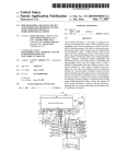
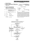
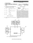
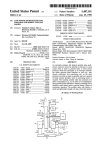
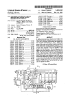
US008466800B1
(12) Ulllted States Patent
(10) Patent N0.:
Billman
(54)
(45) Date of Patent:
SMOKE DETECTOR TESTING
5,905,438 A
.
-
lnvemor-
13281111)’ Jay Blllmall, San AIIIOIHO, TX
(
(73)
'
_
Assrgnee:
)
United Services Automobile
Association (USAA), San Antonio, TX
(US)
10/2000
6,172,612 B1
l/200l
21
Notice:
Subject to any disclaimer, the term of this
patent is extended or adjusted under 35
U_S_C_ 154(1)) by 743 days_
Hoshi
......................... .. 504/131
OdachoWski
6,288,637 B1,.
9/2001 Thomas et a1‘ “““““““ “ 340/506
6,838,988 B2*
7,397,359 B2
2006/0229108 A1*
l/2005 LennartZ et al. ....... .. 340/539.26
7/2008 Sparacino
10/2006 Cehelnik .................. .. 455/5691
2007/0080819 A1
2008/0291036 A1
4/2007 Marks et al.
11/2008 Richmond
2009/0174562 Al*
(*)
Jun. 18, 2013
5/1999 Weiss et a1.
6,140,269 A *
(75)
US 8,466,800 B1
7/2009
Jacobus et al. ........... .. 340/636.l
OTHER PUBLICATIONS
FirstAlert User’s Manual Remote Flashlight Test Smoke Alarm With
Silence Feature (SA88B, SA88C) & Remote Flashlight Test Smoke
APP 1.NO.Z 12/2471 417
Alarm with Silence Feature and 2-Year Extended Life Battery
Filed:
First Alert User’s Manual Smoke and Fire Alarm, Remote Flashlight
(SA89B, SA89C).
(22)
Oct. 8, 2008
Test Smoke Alarm & Remote Flashlight Test Smoke Alarm With
Related US. Application Data
(62)
(51)
of application No. 12/139,901, ?led on Jun.
Int Cl
Escape Light Feature (models SA90B, SA150B).
* Cited by examiner
Primary Examiner * Brian Zimmerman
ASSl'SZLlI’lZ Examiner i James
(52)
(58)
us CL
(74) Attorney, Agent, or Firm * Brooks, Cameron &
USPC ....................... .. 340/636.1; 340/500; 340/628
Hue/b50113 PLLC
Field of Classi?cation Search
USPC ............... .. 340/500, 540, 603, 627, 628, 633,
(57)
340/634
See application ?le for complete Search history,
A testing device is provided that may be attachable and
detachable from a smoke detector. The testing device may
ABSTRACT
References Cited
have a rod that pushes a testing button on the smoke detector.
The testing device may have a li t detector Which Will actu
U.S. PATENT DOCUMENTS
ate the rod to push the testing button if the light from an
appropriate remote control or other light source is directed
56
Bellavia et a1. ............. .. 340/514
onto it, in order to verify that the smoke detector is operating
4,827,244 A *
5/1989
4,827,444 A
5/1989 Akiyama et a1.
properly Without manually pushing the testing button. The
4,870,394 A *
4,901,056 A *
9/1989
2/1990
4,954,816 A
9/1990 Mattison
testing device may store a unique identi?er (1D) and generate
and transmit data pertaining to results of the testing of the
Corlet a1.
.... .. 340/630
Bellavia et a1. ............. .. 340/514
5,140,269 A *
8/1992
5,283,816 A
5,594,410 A
2/1994 Gomez Diaz
l/l997 Lucas etal.
Champlin ................... .. 324/433
smoke detector.
21 Claims, 5 Drawing Sheets
137
130
139
A O
US. Patent
Jun. 18, 2013
Sheet 1 of5
US 8,466,800 B1
137
130
1 39
FIG. 1
source
210
Test circuit
122
2 O
FIG. 2
US. Patent
Jun. 18, 2013
Sheet 2 of5
US 8,466,800 B1
350
¢
Computing
device 370
Q
FIG. 3
5'10
510
B
510
C
530
A
550
530
B
530
C
510
530
Computing
N
N
device 570
5 0
FIG. 5
US. Patent
Jun. 18, 2013
Sheet 3 of5
US 8,466,800 B1
410
Attach testing device to smoke detector
i
Shine light onto testing device using
420
/
remote control; detect light at testing
device
i
430
Trigger test circuit; actuate rod on testing /
device; rod pushes testing button on
smoke detector to test smoke detector
i
440
Testing device generates data pertaining
to test
i
450
Provide data to remote control
i
460
Remote control receives and stores data
i
470
Provide data to computing device for
storage, display, analysis, etc.
/
480
Detach testing
FIG. 4
device from
@
smoke detector
US. Patent
Jun. 18, 2013
Sheet 4 of5
US 8,466,800 B1
610
Attach testing devices to smoke detectors
1
620
Shine light onto one of the testing devices /
using remote control; detect light at testing
device
i
630
Trigger test circuit; actuate rod on testing /
device; rod pushes testing button on
smoke detector to test smoke detector
i
640
Testing device generates data pertaining
to test, including unique ID
i
650
Provide data to remote control
i
660
Remote control receives and stores data
l
Provide data to computing device for
storage, display, analysis, etc.
/
670
680
/
Detach testing
FIG. 6
device(s) from
M
smoke detector(s)
US. Patent
Jun. 18,2013
Sheet 5 005
|r __________________________ __:
|
i
:
:
704
System Memory
'
'
'
i
Removable Storage
i
708
:
:
Non-Removable
Storage 710
|
|
.
vo'ah'e
i
i
I
US 8,466,800 B1
Processing
Unit 702
|
i
Output Device(s)
716
l
I
Non-VolatHe
l
:
l
:
:
|
I
|
___________________________ __l
Input Device(s) 714
Communication
Connect|on(s) 712 \|—
US 8,466,800 B1
1
2
SMOKE DETECTOR TESTING
identify key features or essential features of the claimed sub
ject matter, nor is it intended to be used to limit the scope of
the claimed subject matter.
CROSS-REFERENCE TO RELATED
APPLICATIONS
BRIEF DESCRIPTION OF THE DRAWINGS
The present application is a divisional patent application of
US. patent application Ser. No. 12/139,901 ?led Jun. 16,
The foregoing summary, as Well as the folloWing detailed
description of illustrative embodiments, is better understood
When read in conjunction With the appended draWings. For
2008, the entirety of Which is hereby incorporated by refer
ence herein. Further, this application is related by subject
matter to that disclosed in the following commonly assigned
the purpose of illustrating the embodiments, there are shoWn
in the draWings example constructions of the embodiments;
application, the entirety of Which is hereby incorporated by
reference herein: US. patent application Ser. No. 12/247,405,
?led concurrently hereWith and entitled “SMOKE DETEC
hoWever, the embodiments are not limited to the speci?c
TOR TESTING”.
that may be used for smoke detector testing;
methods and instrumentalities disclosed. In the draWings:
FIG. 1 is a block diagram of an implementation of a system
FIG. 2 is a diagram of an implementation of a smoke
BACKGROUND
A smoke detector is a device that detects smoke and issues
an alarm to alert nearby people that there is a potential ?re.
Because smoke rises, most smoke detectors are mounted on
the ceiling or on a Wall near the ceiling. Virtually all modern
smoke detectors come equipped With a test button that acti
detector testing system;
FIG. 3 is a block diagram of another implementation of a
system that may be used for smoke detector testing;
20
FIG. 4 is an operational ?oW of an implementation of a
detected. Such testing is may be used to verify that the smoke
method that may be used for smoke detector testing;
FIG. 5 is a block diagram of another implementation of a
system that may be used for smoke detector testing;
FIG. 6 is an operational ?oW of another implementation of
a method that may be used for smoke detector testing; and
FIG. 7 is a block diagram of an example computing envi
ronment in Which example embodiments and aspects may be
detector is Working properly. Such detection circuitry usually
implemented.
vates a test function. The purpose of the test function is to
provide a means to test the poWer supply and/or the associated
25
detection circuitry prior to actual smoke having been
includes a manually operable push button sWitch for the pur
pose of initiating the detector test function.
Some smoke detectors include an integrated photosensor.
A control beam of incident electromagnetic energy can be
30
FIG. 1 is a block diagram of an implementation of a system
100 that may be used for smoke detector testing. A smoke
detector 110 is provided and may be any conventional smoke
provided from a remotely located portable source such as a
?ashlight. Directing the beam of radiant energy from the
?ashlight against the smoke detector’s photosensor causes
35
SUMMARY
A testing device is provided that may be attachable and
40
45
properly Without manually pushing the testing button. The
testing device may store a unique identi?er (ID) and generate
and transmit data pertaining to results of the testing of the
50
red (IR) light from a remote control. The IR light may trigger
the testing device to test the smoke detector.
In an implementation, the remote control may be an IR
enabled device. The remote control may be integrated Within
a mobile device such as a mobile phone, personal digital
assistant (PDA), or a handheld computing device.
In an implementation, the remote control may be integrated
55
Within or in communication With a computing device such as
a personal computer (PC), a mobile phone, PDA, or handheld
computing device. The remote control and/or the computing
device may collect, store, analyZe, and/or display data per
taining to the testing of the smoke detector With the testing
60
device.
This summary is provided to introduce a selection of con
cepts in a simpli?ed form that are further described beloW in
the detailed description. This summary is not intended to
residence or business. Although the illustrative embodiments
described herein describe the testing of a smoke detector, any
type of detector or alarm device may be tested, such as a ?re
detector, a heat detector, and a carbon monoxide detector. It is
contemplated that any type of detector With a test circuit or
testing button may be used With the example embodiments
and aspects described herein.
Generally, for example, the smoke detector 110 may have
onto it, in order to verify that the smoke detector is operating
smoke detector.
In an implementation, the testing device may receive infra
detector, such as a residential or business smoke detector that
is poWered by batteries or is Wired into the circuitry of the
the smoke detector to initiate a test sequence.
detachable from a smoke detector. The testing device may
have a rod that pushes a testing button on the smoke detector.
The testing device may have a light detector Which Will actu
ate the rod to push the testing button if the light from an
appropriate remote control or other light source is directed
DETAILED DESCRIPTION
65
a circular plastic housing 111 With a front side 112 and a rear
side 113. The housing 111 has in the region of the front side
thereof a plurality of slots 116 Which permit the entry of
smoke, heat and the like into the housing 111 and permit an
audible alarm sound generated by the smoke detector to leave
the housing 111. In approximately the middle of the front side
of the housing 111 is a push-to-test button 115 (referred to
herein as a “testing button”), Which can be manually pushed
to trigger an alarm, via a test circuit 122 (shoWn in FIG. 2), in
order to verify that the smoke detector 110 is operating prop
erly. Near the testing button 115 may be an operating light
emitting diode (LED) 119 Which may periodically ?ash to
indicate the smoke detector 110 is operating.
A testing device 130 is separate from the smoke detector
110 and is removable such that the testing device 130 may be
attachable and detachable from the smoke detector 110. The
testing device 130 may have a rod 135 that pushes the testing
button 115. The testing device 130 may have a light detector
137 Which Will actuate the rod 135 to push the testing button
115 if the light from an appropriate remote control or other
light source is directed onto it, in order to verify that the
smoke detector 110 is operating properly Without manually
pushing the testing button 115.
US 8,466,800 B1
3
4
The testing device 130 may store a unique identi?er (ID)
and generate and transmit data pertaining to results of the
testing of the smoke detector. In an implementation, the test
devices include universal remote capabilities for other types
of devices, Which alloW the remote control to control other
devices beyond the device it came With. IR learning remotes
ing device 130 may comprise a controller, a processor, one or
can learn the code for any button on many other IR remote
program modules, and/or storage, shoWn collectively as 139,
that may be appropriately con?gured to perform such func
tionality. For example, the testing device 130 may detect the
alarm that results from the testing button 115 being pushed if
the smoke detector 110 is operating properly. The testing
controls. This functionality alloWs the remote control to learn
functions not supported by default for a particular device,
making it sometimes possible to control devices that the
remote control Was not originally designed to control. It is
contemplated that any of these types of remote controls may
device 130 may record Whether or not an alarm Was detected
be used in accordance With the examples and embodiments
described herein.
FIG. 3 is a block diagram of another implementation of a
system 300 that may be used for smoke detector testing. A
smoke detector 110 With an attached testing device 130 is
pursuant to a test along With a date and time, for example.
Such data may be provided to a remote control and/or a
computing device as described further herein.
The testing device 130 may be adapted to ?t on any type of
smoke detector, as a ?at pack With probes (installed betWeen
the connection points of the testing button 115) or as an
extending piece, for example, that may be mounted on the
smoke detector 110 over the testing button 115 or in proxim
ity of the testing button 115. The testing device 130 may be
attached to the casing of the smoke detector 110 by a user
20
using an adhesive or other mechanical means and/or hard
Ware for example. The testing device 130 may be detached or
otherWise removed from the smoke detector 1 1 0 by the user at
any time. In an implementation, the testing device may be
poWered by the smoke detector 110 or may be poWered by
as one of the IR remote controls described above. Altema
25
batteries.
FIG. 2 is a diagram of an implementation of a smoke
detector testing system 200. The smoke detector 110 is con
nected to a poWer source 210, such as an alternating current or
direct current voltage source. The testing device 130 may
comprise an electronic sWitch 232 and a physical (e.g.,
mechanical) switch 235. The electronic switch 232 may com
30
or handheld computing device for example. The remote con
trol 350 and/or the computing device 370 may collect data
diode or an infrared (IR) sensitive phototransistor for
35
pertaining to the testing of the smoke detector 110 With the
testing device 130. In an implementation, the remote control
350 may receive data from the testing device 130, and may
provide some or all of the data to the computing device 370.
The remote control 350 and/or the computing device 370 may
40
store, analyZe, and/ or display the collected data. An example
computing device is described With respect to FIG. 7.
testing button 115 on the smoke detector 110. The electronic
sWitch 232 may be activated by a light source 250, such as an
IR light source.
In an alternative implementation, When IR light is present,
the electronic sWitch 232 may act as an electronic trigger that
charges a test circuit 122 in the smoke detector 110, bypassing
the testing button 115. In such a scenario, the physical sWitch
235 may not be used.
A remote control may act as the light source 250 and may
tively or additionally, the remote control 350 may be inte
grated Within a mobile device such as a mobile phone, per
sonal digital assistant (PDA), or a handheld computing
device. It is contemplated that any light source that provides
IR light may be used as the remote control 350.
In an implementation, the remote control 350 may be inte
grated Within or in communication With a computing device
370 such as a personal computer (PC), a mobile phone, PDA,
prise the light detector 137 and may comprise a light detecting
example. The electronic sWitch 232 may actuate the physical
sWitch 235 comprising the rod 135 for example, to push the
shoWn as receiving IR light 355 from a remote control 350. In
an implementation, the presence of any IR light (e.g., for a
predetermined amount of time such as at least one second)
may trigger the testing device 130 to test the smoke detector
110. Alternatively or additionally, a certain frequency of IR
light may trigger the testing device 130 to test the smoke
detector 110.
The remote control 350 may be an IR enabled device, such
FIG. 4 is an operational How of an implementation of a
method 400 that may be used for smoke detector testing. At
410, a testing device that is removable may be attached to a
45
provide IR light to the testing device 130. A remote control is
smoke detector. At 420, a user may shine a light, such as IR
light, onto the testing device using a remote control or other
an electronic device, typically poWered by batteries, that is
light source, and the testing device may detect the light. Upon
used for the remote operation of a machine. Commonly,
to televisions or other consumer electronics such as stereo 50
receiving the light, the testing device may cause a test circuit
of the smoke detector to be triggered at 430. In an implemen
tation, a rod of the testing device may be actuated at 430, and
systems and video players. Remote controls for these devices
the rod may push the testing button, thereby testing the smoke
are usually small Wireless handheld objects With an array of
detector.
remote controls are used to issue commands from a distance
At 440, the testing device may generate data pertaining to
buttons for adjusting various settings such as channel, track
number, and volume. Remote controls may be single channel
(single-function, one-button) or multi-channel (normal
55
multi-function).
Many remote controls communicate to their respective
devices via IR signals. A near infrared diode may be used to
emit a beam of light that reaches the device. Such a remote
control may be used to emit a beam of light toWards to the
60
display, analysis, etc. In an implementation, the testing device
may provide the data directly to the computing device. At any
time, shoWn at 480, the testing device may be detached from
the smoke detector, e.g., by the user.
65
system 500 that may be used for smoke detector testing.
testing device 130. A 940 nm Wavelength LED is typical,
although any Wavelength(s) of IR may be used.
A universal remote is a remote control that can be pro
grammed to operate various brands of one or more types of
consumer electronics devices. Some universal remotes alloW
the test, such as results, e. g., pass or fail, and date and time of
testing, and provide the data to the remote control at 450. The
remote control may be in a mode to receive data (e. g., a
program mode) and may receive and store the data at 460 in
associated internal or external storage and/ or may provide the
data to a computing device at 470 for subsequent storage,
FIG. 5 is a block diagram of another implementation of a
the user to program in neW control codes to the remote con
Multiple testing devices 530A through 530N, Where N may
trol. Many remote controls sold With various electronic
be any number, may be disposed on associated smoke detec
US 8,466,800 B1
5
6
tors 510A through 510N, respectively. Each testing device
ing environments may be used Where tasks are performed by
may have a unique ID that may be stored in storage associated
remote processing devices that are linked through a commu
nications netWork or other data transmission medium. In a
With the testing device.
A remote control 550 may activate any one of the testing
distributed computing environment, program modules and
devices 53 0A-530N at a particular time by providing IR light
555 to the testing device, thereby testing the smoke detector
associated With that testing device. The remote control 550
may be able to activate each of the testing devices 530A
530N. In an implementation, the same IR (e.g., frequency,
duration, etc.) may be used to activate each of the testing
other data may be located in both local and remote computer
storage media including memory storage devices.
With reference to FIG. 7, an exemplary system for imple
menting aspects described herein includes a computing
device, such as computing device 700. In its most basic con
?guration, computing device 700 typically includes at least
devices 530A-530N.
one processing unit 702 and system memory 704. Depending
on the exact con?guration and type of computing device,
A computing device 570, either integrated With the remote
control 550 or separate from the remote control 550, may be
in communication With the remote control 550, and may
receive and store data associated With the tests of the smoke
detectors 510A-510N. Each testing device may send its ID to
the remote control 550 and/or the computing device 570
along With the data. The ID along With the associated data
may be stored by the remote control 550 and/or the computing
device 570. After receiving the data from the remote control
system memory 704 may be volatile (such as random access
memory (RAM)), non-volatile (such as read-only memory
(ROM), ?ash memory, etc.), or some combination of the tWo.
This most basic con?guration is illustrated in FIG. 7 by
dashed line 706.
Computing device 700 may have additional features and/or
20
550 and/or the testing device(s) 530A-530N, the computing
device 570 may use tools, applications, and aggregators, for
example, to store, analyZe, and/or display the data.
FIG. 6 is an operational How of another implementation of
a method 600 that may be used for smoke detector testing. At
610, testing devices may be attached to smoke detectors, one
25
testing device to each smoke detector. Each testing device
may be removable and may have a unique ID. At 620, a user
may shine a light, such as IR light, onto one of the testing
devices using a remote control, to test associated smoke
30
detector. The testing device may detect the light. At 630, the
test circuit of the associated smoke detector may be triggered
responsive to the testing device detecting the IR light. In an
implementation, the testing device’s rod may be actuated and
may push the smoke detector’s testing button, thereby testing
functionality. For example, computing device 700 may
include additional storage (removable and/ or non-removable)
including, but not limited to, magnetic or optical disks or tape.
Such additional storage is illustrated in FIG. 7 by removable
storage 708 and non-removable storage 710.
Computing device 700 typically includes a variety of com
puter-readable media. Computer-readable media can be any
available media that can be accessed by computing device
700 and include both volatile and non-volatile media, and
removable and non-removable media. By Way of example,
and not limitation, computer-readable media may comprise
computer storage media and communication media.
Computer storage media include volatile and non-volatile,
and removable and non-removable media implemented in any
method or technology for storage of information such as
35
the smoke detector.
computer-readable instructions, data structures, program
modules or other data. System memory 704, removable stor
age 708, and non-removable storage 710 are all examples of
At 640, responsive to the test, the testing device may gen
erate data such as an ID, results, e.g., pass or fail, and date and
computer storage media. Computer storage media include,
time of testing, and provide the data to the remote control at
but are not limited to, RAM, ROM, Electrically Erasable
650. The remote control may store the data at 660 in associ
40
Programmable Read-Only Memory (EEPROM), ?ash
ated internal or external storage and/or may provide the data
to a computing device at 670 for subsequent storage, display,
analysis, etc. In an implementation, the data may be provided
memory or other memory technology, CD-ROM, digital ver
satile disks (DVD) or other optical storage, magnetic cas
directly to the computing device from the testing device. At
netic storage devices, or any other medium Which can be used
to store the desired information and Which can be accessed by
any time, shoWn at 680, one or more of the testing devices
may be detached from their associated smoke detectors.
settes, magnetic tape, magnetic disk storage or other mag
45
computing device 700. Any such computer storage media
may be part of computing device 700.
Computing device 700 may also contain communication
connection(s) 712 that alloW the computing device 700 to
Exemplary Computing Arrangement
FIG. 7 shoWs an exemplary computing environment in
Which example embodiments and aspects may be imple
mented. The computing system environment is only one
50
example of a suitable computing environment and is not
communicate With other devices. Communication connec
tion(s) 712 is an example of communication media. Commu
intended to suggest any limitation as to the scope of use or
nication media typically embody computer-readable instruc
functionality.
tions, data structures, program modules, or other data in a
Numerous other general purpose or special purpose com
puting system environments or con?gurations may be used.
modulated data signal such as a carrier Wave or other transport
55
mechanism, and include any information delivery media. The
Examples of Well knoWn computing systems, environments,
term “modulated data signal” means a signal that has one or
and/ or con?gurations that may be suitable foruse include, but
more of its characteristics set or changed in such a manner as
are not limited to, PCs, server computers, handheld or laptop
to encode information in the signal. By Way of example, and
devices, multiprocessor systems, microprocessor-based sys
not limitation, communication media include Wired media
tems, netWork PCs, minicomputers, mainframe computers,
embedded systems, distributed computing environments that
60
include any of the above systems or devices, and the like.
Computer-executable instructions, such as program mod
media as used herein includes both storage media and com
ules, being executed by a computer may be used. Generally,
program modules include routines, programs, objects, com
ponents, data structures, etc. that perform particular tasks or
implement particular abstract data types. Distributed comput
such as a Wired netWork or direct-Wired connection, and
Wireless media such as acoustic, radio frequency (RF), infra
red, and other Wireless media. The term computer-readable
munication media.
65
Computing device 700 may also have input device(s) 714
such as a keyboard, mouse, pen, voice input device, touch
input device, etc. Output device(s) 716 such as a display,
US 8,466,800 B1
8
7
speakers, printer, etc. may also be included. All these devices
detecting light at a ?rst one of the plurality of physically
detachable testing devices; and
are well known in the art and need not be discussed at length
here.
Computing device 700 may be one of a plurality of com
puting devices 700 inter-connected by a network. As may be
in response to detecting the light, testing a ?rst one of the
associated plurality of preexisting detectors associated
with the ?rst one of the plurality of physically detach
able testing devices by remotely causing a rod on the ?rst
one of the plurality of physically detachable testing
appreciated, the network may be any appropriate network,
each computing device 700 may be connected thereto by way
of communication connection(s) 712 in any appropriate man
ner, and each computing device 700 may communicate with
devices to be actuated to push a testing button on the ?rst
one of the associated plurality of preexisting detectors.
2. The method of claim 1, wherein each of the plurality of
physically detachable testing devices has a unique identi?er.
3. The method of claim 2, further comprising generating a
?rst data set at the ?rst one of the plurality of physically
detachable testing devices pertaining to a result of testing the
?rst one of the associated plurality of preexisting detectors,
the ?rst data set comprising the unique identi?er of the ?rst
one of the plurality of physically detachable testing devices
and the result of testing the ?rst one of the associated plurality
one or more of the other computing devices 700 in the net
work in any appropriate manner. For example, the network
may be a wired or wireless network within an organization or
home or the like, and may include a direct or indirect coupling
to an external network such as the lntemet or the like.
It should be understood that the various techniques
described herein may be implemented in connection with
hardware or software or, where appropriate, with a combina
tion of both. Thus, the methods and apparatus of the presently
disclosed subject matter, or certain aspects or portions
thereof, may take the form of program code (i.e., instructions)
embodied in tangible media, such as ?oppy diskettes, CD
ROMs, hard drives, or any other machine-readable storage
medium wherein, when the program code is loaded into and
20
?rst data set.
5. The method of claim 4, wherein storing the ?rst data set
comprises storing the ?rst data set at a remote control or a
computing device.
executed by a machine, such as a computer, the machine
becomes an apparatus for practicing the presently disclosed
25
subject matter. In the case of program code execution on
programmable computers, the computing device generally
includes a processor, a storage medium readable by the pro
cessor (including volatile and non-volatile memory and/or
storage elements), at least one input device, and at least one
detachable testing devices;
plurality of physically detachable testing devices, test
30
generating a second data set at the second one of the plu
rality of physically detachable testing devices pertaining
35
testing devices; and
providing the second data set to the remote control or the
40
computing device.
7. The method of claim 1, wherein the light comprises
Although exemplary embodiments may refer to utiliZing
infrared light generated by a remote control or a computing
device.
aspects of the presently disclosed subject matter in the context
45
8. A non-transitory computer-readable medium compris
ing computer-readable instructions for detector testing, said
computer-readable instructions comprising instructions that:
detect light at a ?rst one of a plurality of physically detach
able testing devices, wherein each of the plurality of
physically detachable testing devices is powered by an
aspects of the presently disclosed subject matter may be
implemented in or across a plurality of processing chips or
devices, and storage may similarly be effected across a plu
to a result of testing the second one of the associated
plurality of preexisting detectors associated with the
second one of the plurality of physically detachable
object-oriented programming language to communicate with
of one or more stand-alone computer systems, the subject
matter is not so limited, but rather may be implemented in
connection with any computing environment, such as a net
work or distributed computing environment. Still further,
ing a second one of the associated plurality of preexist
ing detectors associated with the second one of the plu
rality of physically detachable testing devices;
One or more programs may implement or utilize the pro
cesses described in connection with the presently disclosed
subject matter, e.g., through the use of an application pro
a computer system. However, the program(s) can be imple
mented in assembly or machine language, if desired. In any
case, the language may be a compiled or interpreted language
and it may be combined with hardware implementations.
6. The method of claim 5, further comprising:
detecting light at a second one of the plurality of physically
in response detecting the light at the second one of the
output device.
gramming interface (API), reusable controls, or the like. Such
programs may be implemented in a high level procedural or
of preexisting detectors.
4. The method of claim 3, further comprising storing the
50
rality of devices. Such devices might include PCs, network
servers, and handheld devices, for example.
Although the subject matter has been described in language
speci?c to structural features and/or methodological acts, it is
associated one of a plurality of preexisting detectors;
and
in response to the light detected, test a ?rst one of the
associated plurality of preexisting detectors associated
appended claims is not necessarily limited to the speci?c
with the ?rst one of the plurality of physically detach
able testing devices by remotely causing a rod on the ?rst
one of the plurality of physically detachable testing
features or acts described above. Rather, the speci?c features
devices to be actuated to push a testing button on the ?rst
and acts described above are disclosed as example forms of
one of the associated plurality of preexisting detectors.
9. The non-transitory computer-readable medium of claim
8, wherein each of the plurality of physically detachable
testing devices has a unique identi?er.
10. The non-transitory computer-readable medium of
claim 9, further comprising instructions that generate a ?rst
to be understood that the subject matter de?ned in the
55
implementing the claims.
60
The invention claimed is:
1. A detector testing method, comprising:
physically attaching a plurality of physically detachable
testing devices to an associated plurality of preexisting
detectors, wherein each of the plurality of physically
detachable testing devices is powered by an associated
one of the plurality of preexisting detectors;
65
data set at the ?rst one of the plurality of physically detach
able testing devices pertaining to a result of testing the ?rst
one of the associated plurality of preexisting detectors, the
?rst data set comprising the unique identi?er of the ?rst one of
US 8,466,800 B1
10
the plurality of physically detachable testing devices and the
detachable testing devices to be actuated to push a test
ing button on the ?rst one of the associated plurality of
result of testing the ?rst one of the associated plurality of
preexisting detectors.
11. The non-transitory computer-readable medium of
preexisting detectors.
16. The system of claim 15, Wherein each of the plurality of
physically detachable testing devices has a unique identi?er.
17. The system of claim 16, further comprising at least one
claim 10, further comprising instructions that store the ?rst
data set.
12. The non-transitory computer-readable medium of
subsystem that generates a ?rst data set at the ?rst one of the
claim 11, Wherein the instructions that store the ?rst data set
comprise instructions that store the ?rst data set at a remote
plurality of physically detachable testing devices pertaining
control or a computing device.
preexisting detectors, the ?rst data set comprising the unique
to a result of testing the ?rst one of the associated plurality of
13. The non-transitory computer-readable medium of
claim 12, further comprising instructions that:
identi?er of the ?rst one of the plurality of physically detach
able testing devices and the result of testing the ?rst one of the
detect light at a second one of the plurality of physically
associated plurality of preexisting detectors.
detachable testing devices;
18. The system of claim 17, further comprising at least one
subsystem that stores the ?rst data set.
19. The system of claim 18, Wherein the at least one sub
system that stores the ?rst data set comprises at least one
in response to the light detected at the second one of the
plurality of physically detachable testing devices, test a
second one of the associated plurality of preexisting
detectors associated With the second one of the plurality
subsystem that stores the ?rst data set at a remote control or a
of physically detachable testing devices;
generate a second data set at the second one of the plurality
20
of physically detachable testing devices pertaining to a
result of testing the second one of the associated plural
ity of preexisting detectors associated With the second
one of the plurality of physically detachable testing
devices; and
the plurality of physically detachable testing devices;
25
the second one of the plurality of physically detachable
testing devices;
30
15. A detector testing system, comprising:
at least one subsystem that detects light at a ?rst one of a
plurality of physically detachable testing devices,
Wherein each of the plurality of physically detachable
35
plurality of preexisting detectors; and
at least one subsystem that tests, in response to the detected
ing a rod on the ?rst one of the plurality of physically
at least one subsystem that generates a second data set at
the second one of the plurality of physically detachable
testing devices pertaining to a result of testing the second
one of the associated plurality of preexisting detectors
associated With the second one of the plurality of physi
cally detachable testing devices; and
at least one subsystem that provides the second data set to
the remote control or the computing device.
21. The system of claim 15, Wherein the light comprises
light, a ?rst one of the associated plurality of preexisting
detectors associated With the ?rst one of the plurality of
physically detachable testing devices by remotely caus
at least one subsystem that tests, in response to the light
detected at the second on of the plurality of physically
detachable testing devices, a second one of the associ
ated plurality of preexisting detectors associated With
computing device.
14. The non-transitory computer-readable medium of
claim 8, Wherein the light comprises infrared light generated
testing devices is poWered by an associated one of a
20. The system of claim 19, further comprising:
at least one subsystem that detects light at a second one of
provide the second data set to the remote control or the
by a remote control or a computing device.
computing device.
40
infrared light generated by a remote control or a computing
device.


![[quote(var.text)]}](http://vs1.manualzilla.com/store/data/005937533_1-4dd3fe8a9b5a28fbfb6fbb268c8e3b66-150x150.png)