1
Software Description AC500 Scalable PLC for Individual Automation Fieldbus Configurator SYCON.net SYCON.net netDevice DTM for PROFIBUS DP Master Devices Generic DTM for PROFIBUS DP Slave Devices ComPro DTM / Ethernet Ethernet Device Configuration DTM for CANopen Master Devices Generic DTM for CANopen Slave Devices DTM for DeviceNet Master Devices Generic DTM for DeviceNet Slave Devices ODMV3 Tray Application ODMV3 Diagnostics Application netConnect Connection Tool Operating Instruction Manual SYCON.net Frame Application Edition: 3 Language: English (EN) ABB STOTZ-KONTAKT GmbH Eppelheimer Straße 82 D-69123 Heidelberg Germany Tel.: +49(0)6221/701-0 Hotline Tel.: +49(0)6221/701-1444 Hotline Fax: +49(0)6221/701-1382 Email Hotline: [email protected] Web: www.abb.de/sto 2 · Introduction SYCON.net List of Revisions Index Date Version Chapter Revision 2 30.08.04 1.0.1.0 Syconu.exe all created 3 02.06.05 1.0.2.2 Syconu.exe 3.1 SYCON.net only with administrator authorization Although this program has been developed with great care and intensively tested, ABB STOTZ-KONTAKT GmbH cannot guarantee the suitability of this program for any purpose not confirmed by us in writing. Guarantee claims shall be limited to the right to require rectification. Liability for any damages which may have arisen from the use of this program or its documentation shall be limited to cases of intent. We reserve the right to modify our products and their specifications at any time in as far as this contribute to technical progress. The version of the manual supplied with the program applies. Copyright · ABB STOTZ-KONTAKT GmbH · Introduction · 3 SYCON.net Table of Contents 1 2 INTRODUCTION.........................................................................................................5 1.1 Short Description SYCON.net .................................................................................. 5 1.2 System Requirements .............................................................................................. 5 SYCON.NET WINDOWS AND MENUS ......................................................................7 2.1 Output Window......................................................................................................... 7 2.2 The Menu Bar .......................................................................................................... 7 2.2.1 2.2.2 2.2.3 3 4 5 File ........................................................................................................................8 View ......................................................................................................................9 Help ....................................................................................................................11 WORKING WITH SYCON.NET.................................................................................13 3.1 Start Program......................................................................................................... 13 3.2 Save Projects......................................................................................................... 14 LISTS ........................................................................................................................15 4.1 List of Figures ........................................................................................................ 15 4.2 List of Tables.......................................................................................................... 16 GLOSSARY...............................................................................................................17 Copyright · ABB STOTZ-KONTAKT GmbH · Introduction · 5 SYCON.net 1 1.1 Introduction Short Description SYCON.net SYCON.net is a FDT frame application to configure communicationcapable fieldbus devices of different manufacturers in one project. In accordance with the FDT Specification 1.2 (Field Device Tool Specification) SYCON.net is used as a frame application for DTMs (Device Type Manager), which are provided, as configuration software by the field device manufacturers. Via the communication channel (Master DTM) the communication with the field devices using protocols like the PROFIBUS is set up. 1.2 System Requirements · PC with 1 GHz processor or higher · Windows 2000/XP · Internet Explorer 5.5 or higher · Free disk space: min. 20 - 30 MByte · CD ROM drive · RAM: min. 256 MByte · Graphic resolution: min. 800 x 600 pixel · Keyboard and Mouse Note: If the project file is saved and opened again or it is used on another PC, the system requirements need to match. Particularly the DTMs need to be installed on the used PC. Copyright · ABB STOTZ-KONTAKT GmbH · SYCON.net Windows and Menus · 7 SYCON.net 2 2.1 SYCON.net Windows and Menus Output Window The Output Window contains index cards, which indicate · information, · warnings and · error messages in plain text. Figure 1: Output Window 2.2 The Menu Bar The menu bar of the configuration software SYCON.net contains pull down menus, via which all available program functions can be called up. Figure 2: Menu bar Note: The two menus Device and Network are not a function of the frame application SYCON.net, but dynamic menus of the FDT of container netDevice. That means these menus are only faded in the menu bar, if the windows netProject or netDevice of the FDT container are activated. Copyright · ABB STOTZ-KONTAKT GmbH · 8 · SYCON.net Windows and Menus 2.2.1 SYCON.net File The File menu contains functions for working on projects. Figure 3: Menu File Menu Meaning Save Saves the actual configuration. Exit Closes the program. If changes of the project file are not stored yet, a dialog appears which requests the user to save the project before ending. Table 1: Menu File Copyright · ABB STOTZ-KONTAKT GmbH · SYCON.net Windows and Menus · 9 SYCON.net 2.2.2 View SYCON.net offers several possibilities for the arrangement and representation of the projects. In the menu View the individual tool bars and windows can be faded in and/or out. Actual indicated tool bars and/or windows are marked in the View menu by a checkmark. Note: The representation in the menu View is dynamic. That means it depends on the components which were installed during installation. Figure 4: Menu View Menu Meaning Statusbar Fade in and out Statusbar. Preset Fade in and out toolbar for different representations of the project. Network Fade in and out Network toolbar. netConnect Fade in and out netConnect window. netDevice Fade in and out netDevice window. netProject Fade in and out netProject window. Output Message Fade in and out Output window. Table 2: Menu View A detailed description about the toolbars can be found in section Toolbars on page 10. Copyright · ABB STOTZ-KONTAKT GmbH · 10 · SYCON.net Windows and Menus 2.2.2.1 SYCON.net Toolbars Frequently used menu functions are united in toolbars: · Preset Toolbar The Preset toolbar gives the possibility to call up to four different representations variants for a project. The respective representation is always stored in the active view. The last representation in the respective view is called up by selecting another representation. Figure 5: Preset Toolbar · Further Toolbars It is possible that toolbars from further installed components are displayed in SYCON.net. For example SYCON.net indicates a network toolbar, which is faded in and/or faded out with the menu View > Network, if the netDevice component is installed. This toolbar contains the functions · Network > Add busline, · Network > Delete last busline and · Network > Load Device Catalog (from left to the right). Figure 6: Network Toolbar Copyright · ABB STOTZ-KONTAKT GmbH · SYCON.net Windows and Menus · 11 SYCON.net 2.2.3 Help The menu Help contains both the documentation about the frame application as well as general information about the software and a reference to the homepage of the manufacturer. Figure 7: Menu Help Menu Meaning Content and Index Opens the documentation of SYCON.net. Hilscher on the WEB Opens the web page of the company Hilscher GmbH. Therefore an existing internet connection is necessary. About Information about the program version. Table 3: Menu Help About Shows the version of SYCON.net. Copyright · ABB STOTZ-KONTAKT GmbH · Working with SYCON.net · 13 SYCON.net 3 3.1 Working with SYCON.net Start Program The configuration software SYCON.net is started from CoDeSys. Copyright · ABB STOTZ-KONTAKT GmbH · 14 · Working with SYCON.net 3.2 SYCON.net Save Projects Via the menu File > Save a project can be saved. If the program is exit and the current configuration does not agree with the last saved configuration, the following question appears: Figure 8: Security Question - Save Project If you answer this question with Yes, the project data are stored. If you answer this question with No, the changed project data are rejected. The saving procedure is aborted by clicking the Chancel button and the project data is not stored. Copyright · ABB STOTZ-KONTAKT GmbH · Lists · 15 SYCON.net 4 4.1 Lists List of Figures Figure 1: Output Window Figure 2: Menu bar Figure 3: Menu File Figure 4: Menu View Figure 5: Preset Toolbar Figure 6: Network Toolbar Figure 7: Menu Help Figure 8: Security Question - Save Project Copyright · ABB STOTZ-KONTAKT GmbH · 7 7 8 9 10 10 11 14 16 · Lists 4.2 SYCON.net List of Tables Table 1: Menu File Table 2: Menu View Table 3: Menu Help 8 9 11 Copyright · ABB STOTZ-KONTAKT GmbH · Glossary · 17 SYCON.net 5 Glossary DTM Device Type Manager A DTM is a software component that serves the Configuration and configuration of field devices. The DTM may have a graphical interface. A DTM that was developed in accordance with the FDT-specification may be integrated into Engineering Tools, Control Systems or configuration software like SYCON.net. The PNO Guideline 2.162 provides a Styleguide describing the design of a DTM. FDT Field Device Tool The FDT Specification (PNO Guideline 2.162) describes how a DTM communicates with a frame application. All the interfaces between a DTM and a frame application are detailed. Copyright · ABB STOTZ-KONTAKT GmbH · Operating Instruction Manual netDevice FDT Container Edition: 3 Language: English (EN) ABB STOTZ-KONTAKT GmbH Eppelheimer Straße 82 D-69123 Heidelberg Germany Tel.: +49(0)6221/701-0 Hotline Tel.: +49(0)6221/701-1444 Hotline Fax: +49(0)6221/701-1382 Email Hotline: [email protected] Web: www.abb.de/sto 2 · Introduction netDevice List of Revisions Index Date Version Chapter Revision 2 01.09.04 1.100 netDevice.ocx all created 3 10.05.05 1.211 netDevice.ocx 3.2.1, Description of "Additional Functions" added, 4.2.1.1, Only administrator authorization, 4.2.1.2 Adding slave DTM or GSD file Although this program has been developed with great care and intensively tested, ABB STOTZ-KONTAKT GmbH cannot guarantee the suitability of this program for any purpose not confirmed by us in writing. Guarantee claims shall be limited to the right to require rectification. Liability for any damages which may have arisen from the use of this program or its documentation shall be limited to cases of intent. We reserve the right to modify our products and their specifications at any time in as far as this contribute to technical progress. The version of the manual supplied with the program applies. Copyright · ABB STOTZ-KONTAKT GmbH · Introduction · 3 netDevice Table of Contents 1 INTRODUCTION.........................................................................................................5 1.1 2 Short Description netDevice ..................................................................................... 5 NETDEVICE WINDOWS.............................................................................................7 2.1 netDevice ................................................................................................................. 7 2.1.1 2.1.2 2.2 3 netProject - Network Folder.................................................................................... 10 WORKING WITH THE MENUS.................................................................................11 3.1 The Menu Bar ........................................................................................................ 11 3.2 Device .................................................................................................................... 11 3.2.1 3.3 4 WORKING WITH NETDEVICE AND NETPROJECT................................................15 4.1 Getting Started - Configuration Steps..................................................................... 15 4.2 The Device Catalog................................................................................................ 16 Insert Device in Project .......................................................................................... 18 4.4 Delete Device from Project..................................................................................... 19 4.5 Working with Buslines ............................................................................................ 20 Description of the Buslines .................................................................................20 Add / Remove Busline ........................................................................................20 Arrange Elements in the Graphical Network View .............................................21 Multiselection......................................................................................................22 CONFIGURATION ....................................................................................................23 5.1 Online/Offline Configuration ................................................................................... 23 5.2 Device Settings and Diagnostics ............................................................................ 24 5.3 Connect/Disconnect Device ................................................................................... 25 5.3.1 5.3.2 7 Load Device Catalog ..........................................................................................16 4.3 4.5.1 4.5.2 4.5.3 4.5.4 6 Additional Functions in the Context Menu..........................................................13 Network.................................................................................................................. 14 4.2.1 5 netDevice - Graphical Network View....................................................................7 netDevice - Device Catalog ..................................................................................9 Download to Device............................................................................................26 Upload from Device ............................................................................................26 LISTS ........................................................................................................................27 6.1 List of Figures ........................................................................................................ 27 6.2 List of Tables.......................................................................................................... 28 GLOSSARY...............................................................................................................29 Copyright · ABB STOTZ-KONTAKT GmbH · Introduction · 5 netDevice 1 1.1 Introduction Short Description netDevice netDevice is a FDT Container for the configuration of field devices of different manufacturers within a FDT frame application. Copyright · ABB STOTZ-KONTAKT GmbH · netDevice Windows · 7 netDevice 2 netDevice Windows 2.1 netDevice The netDevice window is divided in two different areas: · netDevice - Graphical Network View On the left side of the netDevice window the actual configuration is shown as graphical network view. A detailed description of the network view you find in section netDevice - Graphical Network View on page 7. · netDevice - Device Catalog On the right side of the netDevice window the installed devices are displayed as tree structure. Further information about this you find in section netDevice - Device Catalog on page 7. 2.1.1 netDevice - Graphical Network View The network view displays the actual project as graphical network structure. Devices can be added by drag and drop from the Device Catalog (see section Insert Device in Project on page 18) and they are displayed as an icon in the network view. On top or underneath the icon the name of the device with the device address and a continuous number for master devices is displayed. The position of the text depends on the direction of the connection line. By a right mouse click on a device symbol, the context menu is opened. It contains all functions like the menu device which is callable over the menu bar and possibly still further functions for configuration and diagnostic. A detailed description about the device menu and the context menu you find in section Device on page 11. The configuration dialog of the appropriate device opens via a double click on a device symbol. Here all device and bus-specific settings can be made. The possibilities of the configuration are manufacturer specific, closer information for device configuration can be taken from the technical manual of the manufacturer. The single elements (devices and bus lines) can be arranged in the graphical network view. More information can be found in section Arrange Elements in the Graphical Network View on page 21. Copyright · ABB STOTZ-KONTAKT GmbH · 8 · netDevice Windows netDevice Figure 1: netDevice - Graphical Network View The graphical network view in the netDevice window is synchronized with the netProject window. That means devices which are inserting in the graphical network view, are also displayed automatically in the netProject window. Also the devices which are inserting in the netProject window are shown in the graphical network view of the netDevice window. Representation of the Device Description The device description is composed as follows: Figure 2: Representation of the device description The Symbolic Name is entered over the context menu of the device and is optional. Further information about this you find in section Change Symbolic Name on page 13. The Device Description is the name of the device and is not editable. The Station Address is the device address on the bus and can be changed in the device settings. The Network ID is the network address of the Master and it is provided automatically when inserting the device. The network ID is static and cannot not be changed. Copyright · ABB STOTZ-KONTAKT GmbH · netDevice Windows · 9 netDevice 2.1.2 netDevice - Device Catalog The Device Catalog displays a list of devices of all DTMs installed on this PC. If the Device Catalog is loaded, it is shown as tree structure in the netDevice window. Figure 3: netDevice - Device Catalog Selecting one of the register cards, the devices can be arranged by Vendor or Device. Via drag and drop the devices can be inserting in the graphical network view or in the netProject window. There the devices can be configured. Further information about working with the Device Catalog you find in section The Device Catalog on page 16. Copyright · ABB STOTZ-KONTAKT GmbH · 10 · netDevice Windows 2.2 netDevice netProject - Network Folder In the netProject the actual configuration is displayed as project tree. The devices can be inserting via drag and drop from the Device Catalog in the netProject window like in the netDevice window. Underneath the device symbol the name of the device and the device address are shown. For Master devices additionally a continuous number is indicated. The context menu of a device is opened by a right mouse click or a double click on the device. Here the device configuration can be set. Devices which are inserted in the graphical network view are also displayed in the netProject and the other way, too. The actual selection is synchronized with the graphical network view. Except of multiselection in netDevice only the first item will be selected in the tree. More about multiselection you find in section Multiselection on page 22. Copyright · ABB STOTZ-KONTAKT GmbH · Working with the Menus · 11 netDevice 3 3.1 Working with the Menus The Menu Bar The both menus Device and Network are dynamic menus of the netDevice FDT Container, which are displayed in the menu bar of the frame application, if one of the windows netProject or netDevice are activated. 3.2 Device The menu Device includes functions like the device parameter or device properties. This menu can be called up via menu bar of the frame application or via the context menu of the device. Calling up via Description Menu bar In the menu bar of the frame application the standard device parameters are shown in the Device menu. The display of this menu is independent from the used device. Context menu (Right mouse click on device) The context menu Device contains the two functions Symbolic Name and Delete device additionally to the functions in the menu bar. A description about this you find in section Additional Functions in the Context Menu on page 13. Further more the context menu can contain additional device parameters, which are not shown in the menu bar. These additional device parameters are manufacturer specific and they are not specified here. Table 1: Device menu - Calling up via menu bar and context menu of the device Figure 4: Device menu In the following table you find a description of the single functions of the Device menu. The standard functions, which are displayed in each case, are described: Copyright · ABB STOTZ-KONTAKT GmbH · 12 · Working with the Menus netDevice Menu Meaning Connect (*1) The menu function Connect is available, as long as the device is offline. Selecting the menu Connect, a connection to the device is built up and the menu options Disconnect, Download and Upload becoming available now. In case of a Master device, only this device will be connected. If the user connects a Slave device, the device will be connected via the communication channel of the Master. So in this case the Master is online, too. When a connection is built up, the name of the device is displayed on a green background. Disconnect (*1) If a device is connected and it should be disconnected, the menu Disconnect has to be selected. When a Master is disconnected, the Slaves of this network get also disconnected. The name of the device is displayed without green background, if the device is disconnected. Download (*1) With the Download menu, the actual configuration is loaded down into this device. A connection to the device is needed to make a download of the configuration. Upload (*1) Selecting the Upload menu, a configuration stored in this device is loaded up to the application. For this menu it is necessary that a configuration is stored in the device. A connection to the device is needed to make an upload. Configuration With the menu Configuration, the device parameters of the actual device are displayed. The device parameters are manufacturer specific and cannot be specified here. For further information about the device parameter of the used device look in the documentation of the manufacturer. Measured Value Selecting the menu option Measured Value, the measurement values of the device is shown. For further information about the measurement look in the documentation of the manufacturer. Simulation Selecting Simulation, an offline simulation for this device is displayed. For further information about the simulation look in the documentation of the manufacturer. Diagnostics With the Diagnostics menu, the Diagnostic functions for this device are shown. The diagnostic functions are manufacturer specific. For further information about the device diagnostic look in the documentation of the manufacturer. Device Properties Selecting the Device Properties, a general device description of the device opens. Table 2: Menu Device Note (*1): The functions Connect, Disconnect, Download and Upload are selectable for each device. If these menu items are supported by the selected device can only be seen after activating this menu. If they are not supported, an error will be reported. Copyright · ABB STOTZ-KONTAKT GmbH · Working with the Menus · 13 netDevice 3.2.1 Additional Functions in the Context Menu The context menu of the device is opened by a right mouse click on the device icon. It contains all functions like the Device menu in the menu bar. Additionally there are two functions in the context menu: 3.2.1.1 Change Symbolic Name The device description is shown as name of the device by default. With the function Symbolic Name it is possible to insert an own name for the devices additionally to the device description. Figure 5: Change Symbolic Name After entering a symbolic name, this name is shown in the windows netDevice and netProject as name of the device. In this case the device description is displayed in squared brackets behind the symbolic name. Fehler! Unbekanntes Schalterargument. Figure 6: Symbolic Name changed 3.2.1.2 Additional Functions The function Additional Functions leads to further submenus. The function Offline compare… or Online compare… etc. serves to compare parameters. If this functions are supported and what these functions execute, is described in the corresponding documentation of the manufacturer of the respective DTM. The function Device Assignment allows a device-dependent device assignement during device configuration. Further information on this item you will find in the help of the manufacturer of the DTM. The dialog Print > Configuration allows to open the editor Project Documentation. Here data for the master configuation and for the master setup can be printed. 3.2.1.3 Delete With the delete function a device is removed from the project. For further information see section Delete Device from Project on page 19. Copyright · ABB STOTZ-KONTAKT GmbH · 14 · Working with the Menus 3.3 netDevice Network The menu Network includes the network depending functions Add/Remove Busline, the Device Catalog and Print Project Data. Note: The menu functions Add Busline and Remove last Busline are independent from the connected hardware; it affects only the graphical display of the bus created in the netDevice window. It does not effect the real hardware configuration. Figure 7: Menu Network Menu Meaning Add Busline Adds a busline to the selected bus in the netDevice window. Delete last Busline Deletes the last busline from the selected bus. Device Catalog Selecting the Device Catalog function, the window of the Device Catalog opens. The Device Catalog can be loaded or if necessary reloaded. More information about the Device Catalog can be found in section The Device Catalog on page 16. Print Project Data With the function Print Project Data the actual project data like project name, the fieldbus command structure and the device parameter are printed out. Table 3: Menu Network netDevice Toolbar The network toolbar is faded in and faded out via the menu View > Device. This toolbar contains the functions · Network > Add busline, · Network > Delete last busline and · Network > Load Device Catalog (from the left to the right). Figure 8: netDevice Toolbar Copyright · ABB STOTZ-KONTAKT GmbH · Working with netDevice and netProject · 15 netDevice 4 4.1 Working with netDevice and netProject Getting Started - Configuration Steps The following table describes the steps to configure a device as it is typical for many cases. It is presupposed that the hardware installation was done. # Action Menu in SYCON.net or in the Host Application Detail information in section Page 1 Adding Slave-DTM respectively GSD-Datei Installing slave DTM respectively copying GSD file in the GSD directory and reloading in SYCON.net via Network > Device Catalog > button Reload Installing Slave DTM and adding GSD file 17 2 Insert Master Mark Master device in the Device Catalog and insert it via drag and drop in the netDevice or netProject window Insert Device 18 3 Set Master Parameter Right mouse click on the Master and select Configuration from the context menu Device depending see help file of the device manufacturer - 4 Insert Slaves Mark Slave devices in the Device Catalog, Insert Device insert them via drag and drop in the netDevice window on the Master busline or in the netProject window on the Master icon 18 5 Configure Slaves devices (e.g. Assign the input and output modules) Make right mouse click on Slave and select Configuration from the context menu Device depending see help file of the device manufacturer - 6 Device Assignment Make right mouse click on the Master and select Device Assignment from the context menu of the device Device depending see help file of the device manufacturer - 7 Arrange Project Arrange Elements in the The Project can be arranged with the mouse in the graphical network view in the Graphical Network View netDevice window 8 Save Project File > Save - - 9 Connect Master Mark the Master, then select Device > Connect or make a right mouse click at the Master, then select Connect from the context menu of the device. Connect/Disconnect Device 25 10 Download Mark the device and select Device > Download or make right mouse click on device and select Download from the context menu Download to Device 26 11 Diagnostics Make right mouse click on device and Device depending select Diagnostics from the context menu see help file of the device of the device manufacturer Table 4: Getting Started - Configuration Steps Copyright · ABB STOTZ-KONTAKT GmbH · 21 - 16 · Working with netDevice and netProject 4.2 netDevice The Device Catalog The Device Catalog is a list with all devices of the DTMs, which are installed on the used PC. A DTM represents one or more devices. Before the devices can be used in the configuration, the DTMs installed on this PC need to be loaded in the Device Catalog. This is done automatically during the first start of the configuration software SYCON.net. 4.2.1 Load Device Catalog Via the menu Network > Device Catalog the device catalog is opened and information like name of the device, bus system, manufacturer and Master channels for the single DTMs are indicated. If a new DTM is installed, the Device Catalog has to be reloaded, to use the new devices for the configuration. Further information about reloading the Device Catalog you find in section Reload Device Catalog on page 17. Figure 9: Device Catalog If the Device Catalog is loaded, the installed devices are displayed in the device catalog depiction of the netDevice window. The devices can be inserting in the project via drag and drop either directly from the Device Catalog window or from the netDevice window. A detailed description about the device catalog depiction in the netDevice window you find in section netDevice - Device Catalog on page 9. Copyright · ABB STOTZ-KONTAKT GmbH · Working with netDevice and netProject · 17 netDevice 4.2.1.1 Reload Device Catalog The device catalog has to be reloaded to use the new devices in the configuration, if new DTMs are installed on the PC. Via the menu Network > Device Catalog the Device Catalog opens and selecting the Reload button, it is searched for installed DTMs on the PC. The DTMs are started and some information like device name, bus system, manufacturer, Master channels are read in again when loading the device catalog. With this information SYCON.net recreates the Device Catalog. The tree structure shows the actual installed devices. Now the devices can be inserted in the project and configured. 4.2.1.2 Installing Slave DTM and adding GSD file In order to insert further slave devices to the device catalog 1) first it is to be checked, if the slave manufacturer provides a DTM. This DTM is to be installed. 2) If no DTM for the slave is available, the GSD file of the device can be used. Therefore § SYCON.net is to be quitted. § The GSD file is to be copied to the directory C:\Programme\Hilscher GmbH\SYCONnet\ABBPBGenericSlaveDTM\ GSD by use of the Windows® Explorer. § SYCON.net is to be restarted. § The device cataloge is to be loaded (see section Reload Device Catalog on page 17). Note: Before a master or slave device is inserted into a project the GSD file must be copied and reloaded. Copyright · ABB STOTZ-KONTAKT GmbH · 18 · Working with netDevice and netProject 4.3 netDevice Insert Device in Project Devices from the Device Catalog are added by drag and drop in the configuration area. With this action a DTM-Instance will be created. Note: Only devices with the same Fieldbus system can be connected to the same network. · Insert Master To insert a Master device in a project, the Master has to be selected in the Device Catalog directly or in the depiction of the device catalog in the netDevice window. Via drag and drop the device is inserting in the project. The device can be inserted in both windows, in the graphical network view of the netDevice and in the project tree of the netProject. These two windows are synchronized; the device is displayed in both windows. Please note: In the netDevice window the Master device has to be inserted on the Root busline (green line). Each insert communication channel has at least one fixed out-bound busline. In the netProject window the Master need to be inserted on the project folder directly. · Insert Slave To insert a Slave device in a project, the device has to be selected in the Device Catalog directly or in the depiction of the device catalog in the netDevice window. Via drag and drop the device is inserting in the project. Please note: In the netDevice window a Slave device only can be inserted directly on the busline which shows graphically the connection to the Master. In case of PROFIBUS this line is colored violet. In the netProject window the Slave device has to be insert on the master icon directly. Note: The violet busline colour is only for PROFIBUS. In case of other bus systems the buslines can be colored differently. It is possible to have more than one PROFIBUS network in a project and therefore more than one Master. Copyright · ABB STOTZ-KONTAKT GmbH · Working with netDevice and netProject · 19 netDevice 4.4 Delete Device from Project To remove a device from the configuration, select the device and click on the Del button on the keyboard or select Delete in the context menu of the device. Before the device is deleted from the project a security question appears if you are sure to delete this device. Figure 10: Security Question Delete Device Note: If a device is deleted, all settings and configurations for this device get lost. If a communication channel should be deleted that has connected Slaves, another security question appears: Figure 11: Security Question Delete entire Network Note: If a device is deleted, which has additional devices assigned to; the entire network is also deleted. This might include Gateways with Sub networks. Copyright · ABB STOTZ-KONTAKT GmbH · 20 · Working with netDevice and netProject 4.5 4.5.1 netDevice Working with Buslines Description of the Buslines · Busline Colors (default) A green colored busline is a Root busline. All Masters are connected to this line. A violet colored busline shows a PROFIBUS line. A grey colored busline is a branch line. This is the connection between the Slave device and the busline of the Fieldbus where the Slave is connected to. Note: In case of other bus systems the busline from the Master to the connected Slaves can have other colors than violet. Violet is only for PROFIBUS. You can drop a Slave or Gateway device to a bus, if it supports the same bus system. 4.5.2 Add / Remove Busline In the graphical network view in the netDevice window the project can be arranged and edited graphically. That means, buslines can be added and removed. Note: The changes add / remove busline in the graphical network view have no effect to the real hardware configuration. · Add Busline First a busline has to be selected, and then the menu Network > Add Busline has to be chosen. A busline is added on the active bus. If more than one bus is selected, the busline is added only at the first selected bus. · Remove Busline Selecting a bus and choosing the menu Network > Remove last Busline the last busline of this bus is removed. If more than one bus is selected, only the busline of the first bus is deleted. Copyright · ABB STOTZ-KONTAKT GmbH · Working with netDevice and netProject · 21 netDevice 4.5.3 Arrange Elements in the Graphical Network View Figure 12: Buslines Buslines and Device Icons can be selected and moved to arrange them in the graphical configuration. To move a busline or an icon it is necessary to select it by clicking on it. A selected busline or device is displayed by a blue colored frame around the icon. · Move Device Icon Each device icon in the project can be moved by clicking and holding the left mouse button. The fixed buslines move with the icons and the built configuration persists. Another possibility to move the device icons is using the cursor keys. If the SHIFT key is pressed, the icons are moved faster. · Move Buslines Busline A is the Root Busline and it can be positioned by holding the mouse button. Busline B is the Branch Line of the Master and can not be moved. If the Master Icon is moved, the busline moves with this icon automatically. Busline C is the basic line of the Fieldbus inherently. It also can not be moved singly, but it is moved with the device icons automatically. Busline D and E are variable added buslines of the Fieldbus. They can be selected and moved or resized. Busline F is the branch line of the Slave device. It is the connection line from the Slave to the bus. This line is moved automatically (like busline B) with the device icon. Copyright · ABB STOTZ-KONTAKT GmbH · 22 · Working with netDevice and netProject 4.5.4 netDevice Multiselection Multiselection makes it possible to select more than one device and/or busline. This is helpful if more than one element should be arranged at the same time. Two possibilities are available for multiselection: · Only with the Mouse Click in the configuration window and hold the mouse button and draw a frame around the elements you want to select. · With Mouse and the SHIFT Key Select the first element with a left mouse click (busline or device icon) and hold the SHIFT key on the keyboard and click on the next elements you want to select. Note: Only buslines, which can be changed manually, can be selected. A description of the single buslines you find in section Arrange Elements in the Graphical Network View on page 21. Copyright · ABB STOTZ-KONTAKT GmbH · Configuration · 23 netDevice 5 5.1 Configuration Online/Offline Configuration The Configuration of a device is done via the menu Device or via the context menu of the device. A distinction is Configuration: · made between offline Configuration and online Offline Parameterizing If a device is parameterized offline in the application, the configuration has to be loaded into the device via the download to transfer the parameter data into the device. When a configuration already exists in the device, this configuration is overwritten by the download of the new parameter. If a parameter data is already stored in the device and has to be loaded into the configuration, you have to make an upload. · Online Parameterizing Requirement for the online parameterizing is that the hardware is installed and can be activated by the application. In case of online parameterizing, the parameter data set in the application is transferred into the device automatically without a download. If the device contains parameter data and supports the online parameterizing, the stored parameter data is transferred to the application without an upload from the device. Note: It is manufacturer specific, if the used device supports an online Configuration. For further information about the used device please ask the hardware manufacturer or see the help file of the device when device dialog is open. Note: Upload and Download are not available for each device. If a device supports these functions is manufacturer specific. For further information about the used device please ask the hardware manufacturer or see the help file of the device when device dialog is open. More information about the Download you find in section Download to Device on page 26. More information about the Upload you find in section Upload from Device on page 26. Copyright · ABB STOTZ-KONTAKT GmbH · 24 · Configuration 5.2 netDevice Device Settings and Diagnostics The device settings and the diagnostic functions of a device can be called up by making a right mouse click on the device or via the menu Device. These two menus can differ, but the functions Connect, Disconnect, Upload and Download are available in both menus, also if the device does not support these functions. Note: In the menu Device you find the standard parameter and diagnostic functions, which are valid for the most devices. In the context menu of the device you find additional manufacturer specific device settings and diagnostic functions. The description of the single device parameter and the diagnostic functions can be found in the help file of the device. To call up the help file for an appointed device depends on the installed DTM. Mostly the help file is called up in the opened device dialog with the Help button or via the F1 key on the keyboard. Copyright · ABB STOTZ-KONTAKT GmbH · Configuration · 25 netDevice 5.3 Connect/Disconnect Device A device can be connected by marking the device and selecting the menu Device > Connect or via the context menu of the device and Connect. If a Master is selected and then Connect, only the Master device is connected. If Connect is selected in case of a marked Slave device, the device is connected via the parent communication channel. That means the Master is connected, too. Now the device is online. This is displayed by a green background of the device description. The connection is necessary for functions like the online parameter. More information about the Download you find in section Download to Device on page 26. More information about the Upload you find in section Upload from Device on page 26. If the device should be disconnected from the bus, the menu Device > Disconnect or the context menu of the device has to be selected and Disconnect. In case of a Master the Slaves of this network will be disconnected, too. That means the Master is connected to the bus automatically, if a Slave is connected; and the Slaves are automatically disconnected, if the Master is disconnected. Copyright · ABB STOTZ-KONTAKT GmbH · 26 · Configuration 5.3.1 netDevice Download to Device Note: It is manufacturer depending if the device supports the Download function. Look up in the manufacturer specific manual for further information. If a device is parameterized in the application program, a download to the device has to be made to transfer the configuration with the parameter data to the device. Note: Before a download can be done a connection to the device has to be built up. This can be done via the menu Device > Connect or via the context menu of the device and the menu point Connect. Therefore see also section Connect/Disconnect Device on page 25. The download is made via the menu Device > Download or via the context menu of the device and then Download. Now the actual configuration in the application program is loaded down into the device. 5.3.2 Upload from Device Note: It is manufacturer depending if the device supports the Upload function. Look up in the manufacturer specific manual for further information. If a device contains parameter data and this parameter data should be loaded into the application program, an upload from the device has to be made. Note: You first have to build a connection to the device via the menu Device > Connect or via a right mouse click on the device and selecting the menu Connect. Therefore see also section Connect/Disconnect Device on page 25. Then you have to select the menu Device > Upload to make an Upload from the device. The actual configuration in the device is loaded into the application program. Copyright · ABB STOTZ-KONTAKT GmbH · Lists · 27 netDevice 6 6.1 Lists List of Figures Figure 1: netDevice - Graphical Network View Figure 2: Representation of the device description Figure 3: netDevice - Device Catalog Figure 4: Device menu Figure 5: Change Symbolic Name Figure 6: Symbolic Name changed Figure 7: Menu Network Figure 8: netDevice Toolbar Figure 9: Device Catalog Figure 10: Security Question Delete Device Figure 11: Security Question Delete entire Network Figure 12: Buslines Copyright · ABB STOTZ-KONTAKT GmbH · 8 8 9 11 13 13 14 14 16 19 19 21 28 · Lists 6.2 netDevice List of Tables Table 1: Device menu - Calling up via menu bar and context menu of the device Table 2: Menu Device Table 3: Menu Network Table 4: Getting Started - Configuration Steps Copyright · ABB STOTZ-KONTAKT GmbH · 11 12 14 15 Glossary · 29 netDevice 7 Glossary Master Master devices determine the data traffic on the bus. A master may send messages without external request, if it is in the possession of the token (bus access authorization). Slave Slave devices are peripheral devices, like for example I/O devices or drives. Slave devices are also called passive participants. They do not receive the bus access authorization. That means, they may only accept received messages from the Master or send a message to the Master after enquiry of the Master. DTM Device Type Manager A DTM is a software component that serves the Configuration and configuration of field devices. The DTM may have a graphical interface. A DTM that was developed in accordance with the FDT-specification may be integrated into Engineering Tools, Control Systems or configuration software like SYCON.net. The PNO Guideline 2.162 provides a Styleguide describing the design of a DTM. FDT Field Device Tool The FDT Specification (PNO Guideline 2.162) describes how a DTM communicates with a frame application. All the interfaces between a DTM and a frame application are detailed. Copyright · ABB STOTZ-KONTAKT GmbH · Operating Instruction Manual DTM for ABB-PROFIBUS Master Devices Configure ABB Master Devices Edition: 5 Language: English (EN) ABB STOTZ-KONTAKT GmbH Eppelheimer Straße 82 D-69123 Heidelberg Deutschland Tel.: +49 (0) 6221/701-0 Hotline Tel.: +49 (0) 6221/701-1444 Hotline Fax: +49 (0) 6221/701-1382 Email Hotline: [email protected] Web: www.abb.de/sto 2 • Introduction ABB DTM for PROFIBUS Master Devices List of Revisions Index Date 3 30.08.04 0.9.4.0 MSTDTM.dll all created 4 25.05.05 1.0.1.0 AmstCfgu.ocx All only administrator authorization 3.4 Section ‘Firmware Download’ created 1.2 1.4 Section ‚Requirements’, no more Windows® NT, Section ‚Dialog Structure of the PROFIBUS Master DTM’ completed, Section ‚Status Bar’ completed, Section ‚Dialog Buttons’ completed, Section ‚Settings’ for ODMV3 dialog reorganized, Section ‚Configuration’ reorganized, Section ‚General’ - reorganized updated, Section ‚Station Table’ completed, Section ‚Address Table’ updated, Section ‚Diagnosis’ reorganized, Section ‚General’ - overview updated, Section ‚Firmware Diagnosis’ completed, Section ‚Bus Diagnosis’ updated, Section ‚Extended Diagnosis’ completed 5 Version 22.11.05 2.010 PROFIBUS ABB Master DTM Chapter Revisions 1.5 1.6 2 3 3.1 3.3 3.4 4 4.1 4.2 4.4 5 Although this program has been developed with great care and intensively tested, ABB STOTZ-KONTAKT GmbH cannot guarantee the suitability of this program for any purpose not confirmed by us in writing. Guarantee claims shall be limited to the right to require rectification. Liability for any damages which may have arisen from the use of this program or its documentation shall be limited to cases of intent. We reserve the right to modify our products and their specifications at any time in as far as this contribute to technical progress. The version of the manual supplied with the program applies. • ABB STOTZ-KONTAKT GmbH Introduction • 3 ABB DTM for PROFIBUS Master Devices Table of Contents 1 INTRODUCTION.........................................................................................................7 1.1 About PROFIBUS Master DTM ..................................................................................7 1.2 Requirements .............................................................................................................7 1.3 Dialog Structure of the PROFIBUS Master DTM ........................................................8 1.3.1 1.3.2 1.3.3 2 1.4 Status Bar .................................................................................................................12 1.5 Dialog Buttons ..........................................................................................................13 SETTINGS ................................................................................................................15 2.1 Overview Settings.....................................................................................................15 2.2 Driver ........................................................................................................................16 2.2.1 2.2.2 2.3 2.4 Selecting Firmware File......................................................................................22 License Codes ..........................................................................................................23 CONFIGURATION ....................................................................................................25 3.1 Overview Configuration ............................................................................................25 3.2 Bus Parameters ........................................................................................................26 3.2.1 3.2.2 3.2.3 3.2.4 3.2.5 4 Scanning Device.................................................................................................19 Assigning Device ................................................................................................20 Firmware Download..................................................................................................21 2.4.1 2.5 Selecting Driver ..................................................................................................16 3S Gateway Driver .............................................................................................17 Device Assignment ...................................................................................................19 2.3.1 2.3.2 3 General Device Information..................................................................................8 Pages Tree-View ..................................................................................................9 Setting, Configuration and Diagnosis Pages......................................................10 Profile .................................................................................................................26 Bus Parameters..................................................................................................27 Bus Monitoring....................................................................................................30 Error Handling ....................................................................................................31 Calculated Timing...............................................................................................32 3.3 Station Table.............................................................................................................33 3.4 Address Table...........................................................................................................34 DIAGNOSIS ..............................................................................................................37 4.1 Overview Diagnosis ..................................................................................................37 4.2 Firmware Diagnosis ..................................................................................................38 4.3 Bus Diagnosis...........................................................................................................39 4.3.1 4.3.2 4.3.3 4.4 Master Operation Mode......................................................................................39 Master Status .....................................................................................................40 Bus Monitoring....................................................................................................41 Station Diagnosis......................................................................................................42 • ABB STOTZ-KONTAKT GmbH 4 • Introduction 4.4.1 4.4.2 5 6 7 Station Status .....................................................................................................42 Station Error .......................................................................................................42 EXTENDED DIAGNOSIS ..........................................................................................43 5.1 Overview Extended Diagnosis..................................................................................43 5.2 PLC - Variables.........................................................................................................45 5.3 USR_INTF - Common Variables ..............................................................................46 5.4 USR_INTF - Running State ......................................................................................47 5.5 USR_INTF - Global State Field ................................................................................48 5.6 USR_INTF - Communication Error ...........................................................................49 5.7 USR_INTF - Parameter Set List ...............................................................................50 5.8 USR_INTF - Last Downl.parameter ..........................................................................50 5.9 USR_INTF - Disconnect Report ...............................................................................51 5.10 USR_INTF - Diagnostic Report ................................................................................52 5.11 FDL - Common Variables .........................................................................................53 5.12 FDL - Bus Parameters ..............................................................................................54 5.13 FDL - DDLM Request cl.1.........................................................................................55 5.14 FDL - DDLM Request cl.2.........................................................................................56 5.15 FDL - FDL request ....................................................................................................57 5.16 FDL - FMA request ...................................................................................................58 5.17 FDL - Data exchange retry .......................................................................................59 5.18 FDL - DP: activated slave .........................................................................................60 5.19 FDL - DPV1 requests................................................................................................61 ONLINE TO THE DEVICE.........................................................................................63 6.1 Connect/Disconnect..................................................................................................63 6.2 Download..................................................................................................................63 ERROR NUMBERS ..................................................................................................65 7.1 Possible PLC Error Messages..................................................................................65 7.2 RCS Error Numbers..................................................................................................66 7.3 Database Access Error Numbers .............................................................................68 7.4 Online Data Manager Error Numbers .......................................................................69 7.4.1 7.4.2 7.4.3 7.4.4 8 ABB DTM for PROFIBUS Master Devices Online Data Manager Error Numbers.................................................................69 Message Handler Error Numbers.......................................................................70 Driver Functions Error Numbers.........................................................................71 Online Data Manager Subfunctions Error Numbers...........................................71 7.5 Data Base Functions Error Numbers ........................................................................72 7.6 Converting Functions Error Numbers .......................................................................76 LISTS ........................................................................................................................77 8.1 List of Figures ...........................................................................................................77 • ABB STOTZ-KONTAKT GmbH Introduction • 5 ABB DTM for PROFIBUS Master Devices 8.2 9 List of Tables ............................................................................................................79 GLOSSARY...............................................................................................................81 • ABB STOTZ-KONTAKT GmbH Introduction • 7 ABB DTM for PROFIBUS Master Devices 1 1.1 Introduction About PROFIBUS Master DTM In this manual the usage of the ABB PROFIBUS Master DTM is described. This DTM is used for the configuration of ABB PROFIBUS-DP Master devices within a FDT Framework. This manual describes the device parameters and diagnostic functions. 1.2 Requirements System Requirements • Windows® 2000/ Windows® XP • CD ROM drive • Graphic resolution: min. 1024 x 768 pixel • Keyboard and Mouse Requirements ABB PROFIBUS Master DTM To configure an ABB PROFIBUS Master device with a DTM the following requirements have to be accomplished: • Completed hardware installation of a DTM-compatible ABB PROFIBUS Master device • FDT/DTM V 1.20 compliant frame application • Installed FDT Framework • Open Project in FDT Framework • Loaded DTM in the Device Catalog of the FTD Framework • ABB STOTZ-KONTAKT GmbH 8 • Introduction 1.3 ABB DTM for PROFIBUS Master Devices Dialog Structure of the PROFIBUS Master DTM The dialog window of the DTM is divided in three different areas: • A header which contains the General Device Information. • The Pages Tree-View displayed as tree structure. • The Setting, Configuration and Diagnosis Pages. Figure 1: Dialog Structure of PROFIBUS Master DTM 1.3.1 General Device Information The general device information contains specifications to the device. This indication is only for information and can not be edited The indicated information is IO Device (name of the device), the Vendor, the Device ID and the Vendor ID. Figure 2: General Device Information • ABB STOTZ-KONTAKT GmbH Introduction • 9 ABB DTM for PROFIBUS Master Devices 1.3.2 Pages Tree-View The left side shows the pages tree-view: Figure 3: Pages Tree-View Settings and Configuration Settings Driver On the page driver the selection list of the existing drivers is displayed. For the individual drivers additional parameters can be adjusted if necessary. Further information you find in the section Driver on page16. Device Assignment This page contains the Device Assignment, where the favored driver can be assigned. Further information about this you find in section Device Assignment on page 19. Firmware Download The dialog on the page Firmware Download is used to load a new firmware into the device. A detailed description can be found in section Firmware Download on page 21. License Codes On the page License Codes current device data are displayed and the license code can be entered. Further information to this item you find in the section License Codes on page 23. Configuration Bus Parameters The Bus Parameters are the basis of an operating data exchange. Further information about setting the bus parameters are described in section Bus Parameters on page 26. Station Table The station table displays the list of all configured slave devices. Further information to the station table can be found in the section Station Table on page 33. Address Table The Address Table shows a list of all addresses used in the process data image. Further information about the address table is described in section Address Table on page 34. Table 1: Overview Settings and Configuration Pages • ABB STOTZ-KONTAKT GmbH 10 • Introduction 1.3.3 ABB DTM for PROFIBUS Master Devices Setting, Configuration and Diagnosis Pages On the setting, configuration and diagnosis pages the device specific settings and the configuration can be made. These one can be edited by entering parameter values or via pull-down menus. On the diagnosis pages diagnosis information out of or to the device can be red and displayed. Therefore a connection to the device is required. Detailed information to the single pages you can find below in this manual. Subsequently the sections with the descriptions to the single setting, configuration and diagnosis pages for the ABB PROFIBUS Master DTM are listed. Settings Contents Page Overview Settings 15 Driver 16 Device Assignment 19 Firmware Download 21 License Codes 23 Table 2: Descriptions Setting Pages Configuration Contents Page Bus Parameters 26 Station Table 33 Address Table 34 Table 3: Descriptions Configuration Pages Diagnosis Contents Page Overview Diagnosis 37 Firmware Diagnosis 38 Bus Diagnosis 39 Station Diagnosis 42 Table 4: Descriptions Diagnosis Pages • ABB STOTZ-KONTAKT GmbH Introduction • 11 ABB DTM for PROFIBUS Master Devices Extended Diagnosis Contents Page PLC - Variables 45 USR_INTF - Common Variables 46 USR_INTF - Running State 47 USR_INTF - Global State Field 48 USR_INTF - Communication Error 49 USR_INTF - Parameter Set List 50 USR_INTF - Last Downl.parameter 50 USR_INTF - Disconnect Report 51 USR_INTF - Diagnostic Report 52 FDL - Common Variables 53 FDL - Bus Parameters 54 FDL - DDLM Request cl.1 55 FDL - DDLM Request cl.2 56 FDL - FDL request 57 FDL - FMA request 58 FDL - Data exchange retry 59 FDL - DP: activated slave 60 FDL - DPV1 requests 61 Table 5: Extended Diagnosis Pages • ABB STOTZ-KONTAKT GmbH 12 • Introduction 1.4 ABB DTM for PROFIBUS Master Devices Status Bar The Status Bar displays information about the current state of the DTM. The meaning of the icons is explained in the following: Figure 4: Status Bar Number Meaning 1 Name of the Master DTM manufacturer: ABB Stotz-Kontakt GmbH 2 Connection State Icon closed = Device is online Icon not closed = Device is offline 3 Offline data: The displayed data are read out from the configuration file (database). Online data: The displayed data are read out online from the device. 4 Configuration was changed This symbol indicates, that the configuration was changed and these changes have not been saved until yet. When saving the actual configuration, this symbol expires. 5 Diagnosis is activated 6 The status of the device is displayed first as icon (6) and below it is indicated in plain text (7). The following states can appear: Info Warning Error Table 6: Elements of the Status Bar • ABB STOTZ-KONTAKT GmbH Introduction • 13 ABB DTM for PROFIBUS Master Devices 1.5 Dialog Buttons OK If it is confirmed with OK, the settings are stored and the dialog is closed. Cancel Clicking the Cancel button it is asked to confirm the loss of all modifications made before. If changes at the configuration were made, a safety inquiry follows whether the changes are to be stored or not. Subsequently, the dialog is closed. Apply The modifications are stored temporary to the frame applications database when clicking the Apply button. The dialog remains opened. Reset By means of the Reset button changes in the configuration of the frame application are rejected. Help For the configuration and diagnosis of the DTM a help file is available. This is opened by clicking the Help button. Selecting, creating, deleting Table Line To select a line in a table or to create a new one or to delete one the available arrow buttons can be used. Button Meaning To select the table’s first line use the button First Line. To select the previous line in the table use the button Previous Line. To select the next line in the table use the button Next Line. To select the last line in the table use the button Last Line. The button Create a new Line inserts new lines into the table. The button Delete selected Line deletes the selected line from the table. Table 7: Meaning of the Buttons selecting, creating, deleting Table Line • ABB STOTZ-KONTAKT GmbH 14 • Introduction ABB DTM for PROFIBUS Master Devices Activating / Deactivating Options To activate an option set a hook into the checkbox. To deactivate an option remove the hook from the checkbox. Activated / deactivated • ABB STOTZ-KONTAKT GmbH Settings • 15 ABB DTM for PROFIBUS Master Devices 2 2.1 Settings Overview Settings Pages tree-view Settings for the PROFIBUS Master DTM: Figure 5: Pages Tree-View - Settings Descriptions to the setting pages for the PROFIBUS Master DTM: Driver Contents Page Selecting Driver 16 3S Gateway Driver 17 Table 8: Setting Pages - Driver Device Assignment Contents Page Scanning Device 19 Assigning Device 20 Table 9: Setting Pages - Device Assignment Firmware Download Contents Page Selecting Firmware 22 Table 10: Setting Pages - Firmware Download License Codes Contents Page License Codes 23 Table 11: Setting Pages - License Codes • ABB STOTZ-KONTAKT GmbH 16 • Settings 2.2 ABB DTM for PROFIBUS Master Devices Driver By means of the driver selection it is determined how the PROFIBUS DTM will communicate with the device which will be assigned later by the device assignment (see section Device Assignment on page 19). 2.2.1 Selecting Driver To select one or several drivers select Settings > Driver from the Pages Tree-View. The Driver dialog with the selection list of the available drivers is shown. Every recognized or installed driver is displayed. Figure 6: Selection List Driver Select the driver/s to be used in the dialog Driver from the selection list (see figure Driver Selection List on page 16). Only drivers can be selected, the connection specifications of which are supported. Only then a communication between the corresponding master DTM and the device can be established. Note: In the device assignment (see section Device Assignment on page 19) a connection from the master DTM to the device shall be established by trying to scan the selected driver/s. Checkbox Description Driver is not selected. Driver is selected. Table 12: Checkbox Driver Mark the desired driver/s in the driver selection list by clicking the appropriate checkbox. • ABB STOTZ-KONTAKT GmbH Settings • 17 ABB DTM for PROFIBUS Master Devices 2.2.2 3S Gateway Driver In the dialog window 3 S Gateway Driver settings can be made on how the configurator can communicate with the device. Figure 7: Settings > Driver > 3S Gateway Driver Term in the dialog Meaning Current Configuration Shows the current configuration of the 3 S Gateway driver. Read Configuration Actualizes the display under Current Configuration Gateway Configuration Opens the window ’Kommunikationsparameter’ (Communication Parameters, see figure 3S Gateway Driver - Communication Parameters on page 18). The communication parameters for the driver configuration can be preset here. Table 13: Description to the 3S Gateway Driver Dialog • ABB STOTZ-KONTAKT GmbH 18 • Settings ABB DTM for PROFIBUS Master Devices In the window ’Kommunikationsparameter’ the communication parameters for the driver configuration can be adjusted. Figure 8: 3S Gateway Driver - Communication Parameters Note: The detailed description to the dialogue window Kommunikationsparameter (communication parameter) is in the ABB manual "Systems Engineering of the CPUs/Coupler". • ABB STOTZ-KONTAKT GmbH Settings • 19 ABB DTM for PROFIBUS Master Devices 2.3 Device Assignment To establish an operating communication between the DTM and a device, a physical device must be assigned to the master DTM. This is done in the Device Assignment. To access the Device Assignment dialog, select Settings > Device Assignment from the Pages Tree-View. The dialog Device Assignment is displayed: Note: Precondition for the device assignment is the previous selection of one or more drivers (see section Driver on page 16). 2.3.1 Scanning Device To start the scanning process, click to the button Scan. Figure 9: Device Assignment - detected Devices In the table Device Assignment all devices are indicated, which can be connected with the DTM via the drivers selected before. For every found device the device name, the serial number, the driver and the access path are displayed. In the field Access Path the access path to the selected device is displayed. • ABB STOTZ-KONTAKT GmbH 20 • Settings 2.3.2 ABB DTM for PROFIBUS Master Devices Assigning Device To assign a driver to a device, first the checkbox at the left side of the desired device/ driver must be marked by a hook. Checkbox Description Device is still not assigned. Device is assigned. Table 14: Device Assignment - Checkbox Device Note: A connection can always only be build up to exactly one device. Figure 10: Device Assignment - Assigning Device Further the selection is to be confirmed by OK or Apply. Now the selected device is connected with the master DTM. By clicking to the button Cancel the Device Assignment dialog will be closed without any assignment or changes of an assignment. Note: To analyze errors which have been occurred during assignment, the diagnostic function ODMV3 Diagnostic Application can be used (for further information see manual ODMV3 Diagnostic Application). • ABB STOTZ-KONTAKT GmbH Settings • 21 ABB DTM for PROFIBUS Master Devices 2.4 Firmware Download Using the Firmware Download dialog a firmware can be transferred to the device, to e. g. load a later version. In this case open the Firmware Download dialog. To access the Firmware Download dialog, select Settings > Firmware Download from the Pages Tree-View. The dialog Firmware Download is displayed. Note: For firmware download a device must be assigned to a driver. See section Driver on page 16. In order to select a firmware file, click on the Browse button. The dialog Select Firmware File opens, in which the firmware file to be loaded can be selected. A description about this dialog you find in section Selecting Firmware on page 22. Figure 11: Firmware Download After opening the firmware file, the Name and the Version of the firmware are indicated in the upper section of the dialog. By clicking the Download button, a safety query appears, if you really want to download the new firmware. Confirm this query with Yes, to download the new firmware. • ABB STOTZ-KONTAKT GmbH 22 • Settings 2.4.1 ABB DTM for PROFIBUS Master Devices Selecting Firmware File In the Select Firmware File dialog window a firmware file can be selected. Therefore select the firmware to be loaded by clicking on it and confirm this selection by clicking on the Open button. In the lower section of the dialog window Select Firmware File the following information is shown: • File name • File type • Recent folders and • Firmware (version number). • ABB STOTZ-KONTAKT GmbH Settings • 23 ABB DTM for PROFIBUS Master Devices 2.5 License Codes To access the License Codes dialog, select Settings > License Codes from the Pages Tree-View. The dialog License Codes is displayed. Figure 12: License Codes After the device has been assigned (see section Device Assignment on page 19), the device data and the available license codes are displayed in the License Codes dialog. If a license code must be registered to the device, enter the license code into the window License Code and click to the Add button. The resulting character code for the device is saved at the device and is displayed in the License Codes dialog under Available Codes. • ABB STOTZ-KONTAKT GmbH Configuration • 25 ABB DTM for PROFIBUS Master Devices 3 3.1 Configuration Overview Configuration Pages Tree-View Configuration for the PROFIBUS Master DTM: Figure 13: Pages Tree-View - Configuration Descriptions to the configuration pages for the PROFIBUS Master DTM: Bus Parameters Page Profile 26 Bus Parameters 27 Bus Monitoring 30 Error Handling 31 Calculated Timing 32 Table 15: Configuration Pages - Bus Parameters Station Table Page 33 Station Table Table 16: Configuration Pages - Station Table Address Table Page Address Table 34 Table 17: Configuration Pages - Address Table • ABB STOTZ-KONTAKT GmbH 26 • Configuration 3.2 ABB DTM for PROFIBUS Master Devices Bus Parameters The Bus Parameters are the basis of an operating data exchange. This section contains information for setting the Bus Parameters as well as the description of the individual parameters. Basic Rule: The Bus Parameters must be set the same for all devices. The Station Address, on the other hand, must be different from device to device. 3.2.1 Profile Figure 14: Bus Parameters > Profile The following Profiles are available for the Hilscher Master DTM: PROFIBUS-DP (Decentralized Periphery) PROFIBUS-PA (Process Automation) According to the selected profile the associated standard bus parameters are displayed when opening the dialog for the first time. Each parameter can be edited. For the PROFIBUS-DP profile several baud rates can be selected. In the PROFIBUS-PA profile the baud rate 93.75 kBit/s is preset. • ABB STOTZ-KONTAKT GmbH Configuration • 27 ABB DTM for PROFIBUS Master Devices 3.2.2 Bus Parameters Figure 15: Bus Parameters > Bus Parameters Caution: The changing of Bus Parameters can cause communication interruptions. Note: The offline Bus Parameters are displayed. The Bus Parameters are transferred to the ABB device after the download of the configuration. A description about the download you find in section Download on page 63. Bus Parameters Meaning Baud Rate The Baud Rate is the data transfer speed: number of Bits per second. The Baud Rate must be set to be the same for all devices on the bus. The result of changing the Baud rate is that all other parameters must be re-calculated. Slot time (TSL) Baud Rate Bit time (tBit) Max cable length (type A) 9,6 kBit/s 19,2 kBit/s 31,25 kBit/s 45,45 kBit/s 93,75 kBit/s 187,5 kBit/s 500 kBit/s 1500 kBit/s 3000 kBit/s 6000 kBit/s 12000 kBit/s 104,2 us 52,1 us 32 us 22 us 10,7 us 5,3 us 2 us 666,7 ns 333,3 ns 166,7 ns 83,3 ns 1200 m 1200 m 1200 m 1200 m 1200 m 1000 m 400 m 200 m 100 m 100 m 100 m 'Wait for receipt' – Monitoring time of the sender (Requestor) of telegram for the acknowledgement of the recipient (Responder). After expiration, a retry occurs in accordance with the value of 'Max. telegram retries'. Value range: 37 .. 16383 (The default value depends from the baud rate.) Min. Station Delay Time (min TSDR) This is the shortest time period that must elapse before a remote recipient (Responder) may send an acknowledgement of a received query telegram. The shortest time period between reception of the last Bit of a telegram to the sending of the first Bit of a following telegram. Value range: 1 .. 11 .. 65535 Max. Station Delay Time (max TSDR) This is the longest time period that must elapse before a Sender (Requestor) may send a further query telegram. Greatest time period between reception of the last Bit of a telegram to the sending of the first Bit of a following telegram. The Sender (Requestor, Master) must wait at least for this time period after the sending of an unacknowledged telegram (e.g. Broadcast only) before a new telegram is sent. Value range: 1 .. 65535 (The default value depends from the baud rate.) More see next page. • ABB STOTZ-KONTAKT GmbH 28 • Configuration Quiet Time (TQUI) ABB DTM for PROFIBUS Master Devices This is the time delay that occurs for modulators (Modulator-trip time) and Repeaters (Repeater-switch time) for the change over from sending to receiving. Value range: 0 .. 127 (The default value depends from the baud rate.) Setup Time (TSET) Minimum period “reaction time” between the receipt of an acknowledgement to the sending of a new query telegram (Reaction) by the Sender (Requestor). Station Address The Station Address is the individual device address of the Master device on the bus. Value range: 0 .. 255 (The default value depends from the baud rate.) Value range: 0 .. 125 Target Rotation Time (TTR) Pre-set nominal Token cycling time within the Sender authorization (Token) will cycle around the ring. How much time the Master still has available for sending data telegrams to the Slaves is dependent on the difference between the nominal and the actual token cycling time. The Target rotation time (TTR) is shown in Bit times (tBit) like the other Bus Parameters. Below the displayed Bit time, the Target rotation time is also displayed in milliseconds (ms). Value range: 1 .. 224-1 (=16.777.215) (The default value depends on the number of Slaves attached to the Master and their module configuration) GAP Actualization Factor (G) Factor for determining after how many Token cycles an added participant is accepted into the Token ring. After expiry of the time period G*TTR, the Station searches to see whether a further participant wishes to be accepted into the logical ring. Value range: 0 .. 10 .. 255 Max. Retry Limit Maximum number of repeats in order to reach a Station. Value range: 1 .. 15 (The default value depends from the baud rate.) Highest Station Address The Highest Station Address is the highest bus address up to which a Master searches (HSA) for another Master at the bus in order to pass on the Token. This station address must on no account be smaller than the Master station address. Value range: 1 .. 126 Table 18: Bus Parameters > Bus Parameters 3.2.2.1 Adjust Bus Parameters If the bus configuration is changed and these changes have effects on the bus parameters, a note symbol appears next to the concerned parameters which displayed values are not longer actual. Figure 16: Note bus configuration was changed, Bus Parameters not longer actual With the Adjust button the bus parameters on basis of the current bus configuration are calculated again and updated in the bus parameter dialog. Figure 17: Button Adjust Bus Parameters If no note symbol is displayed next to the parameters of the bus configuration, the indicated values are current and valid. • ABB STOTZ-KONTAKT GmbH Configuration • 29 ABB DTM for PROFIBUS Master Devices 3.2.2.2 Additional Conditions for correct Communication TQUI < min TSDR TRDY < min TSDR TQUI < TRDY 3.2.2.3 Representation of the Bus Parameters All times for the Bus parameters are given in Bit times. The Bit time tBit is the result of the reciprocal of the Baud rate: tBit = 1 / Baud rate (Baud rate in Bit/s) The conversion from milliseconds into a Bit time is shown in the following formula: Bit time = Time [milliseconds] * Baud rate • ABB STOTZ-KONTAKT GmbH 30 • Configuration 3.2.3 ABB DTM for PROFIBUS Master Devices Bus Monitoring Figure 18: Bus Parameters > Bus Monitoring Bus Parameters Meaning Data Control Time The Data Control Time defines the time within the Data_Transfer_List is updated at least once. After the expiration of this period, the Master (class 1) reports its operating condition automatically via the Global_Control command. Value range: 1 .. 232-1 (= 4.294.967.295) (The default value depends from the baud rate.) Min. Slave Interval The Min Slave Interval defines the minimum time period between two Slave list cycles. The maximum value that the active Stations require is always given. Value range: 1 .. 65535 (The default value depends on the Slave types) Override slave specific Watchdog Control Time Each Slave returns a specific Watchdog Control Time to the Master. The option Override slave specific Watchdog Control Time allows the user to override individual slave specific settings with an equal value for all slaves configured at this master, for example to set a consistent value for slower transmission rates (which may require extended Watchdog Control Times) in critical environments. Watchdog Control Time The DP Slaves utilizes the Watchdog Control Time setting in order to detect communication errors to the assigned Master. When the Slave finds an interruption of an already operational communication, defined by a Watchdog time, then the Slave carries out an independent Reset and places the outputs into the secure condition. Value range: 0 .. 65025 (The default value depends on the number of Slaves attached to the Master and their configuration) Table 19: Bus Parameters > Bus Monitoring • ABB STOTZ-KONTAKT GmbH Configuration • 31 ABB DTM for PROFIBUS Master Devices 3.2.3.1 Adjust Bus Monitoring Parameter If the bus configuration is changed and these changes have effects on the bus monitoring parameters, a note symbol appears next to the concerning parameters which displayed values are not longer current. Figure 19: Note Bus configuration was changed, Bus Monitoring Parameters not longer actual With the Adjust button the bus parameters on basis of the current bus configuration are calculated again and updated in the bus parameter dialog. Figure 20: Button Adjust Bus Monitoring Parameters If no note symbol is displayed next to the parameters of the bus monitoring configuration, the indicated values are current and valid. 3.2.4 Error Handling Figure 21: Bus Parameters > Error Handling For PROFIBUS-DP, the Auto Clear setting is provided for global error handling. The DP Master monitors the data exchange to all DP Slaves by means of a timer. • Auto Clear ON (Enabled) The Masters Operation Mode (see section Master Operation Mode on page 39) will change from Operate to Clear and it shuts down the communication to all assigned Slaves, if at least one Slave is not responding within the Data Control Time (see section Bus Monitoring on page 30). • Auto Clear OFF (Not Selected) The Master Operation Mode (see section Master Operation Mode on page 39) will stay in the mode Operate and the communication to all available Slaves is kept up. • ABB STOTZ-KONTAKT GmbH 32 • Configuration 3.2.5 ABB DTM for PROFIBUS Master Devices Calculated Timing Note: The Calculated Timing cannot be set; they result from the given calculations. The display of these times is only for information. Figure 22: Bus Parameters > Calculated Timing The Calculated Timing is the time that the Sender spends at idle after the receipt of the last Bit of a telegram on the Bus, until the first Bit of a new telegram is sent on the Bus. Depending on the type of the telegram: Bus Time Meaning Formula Tid1 Tid1 starts after the Initiator has received an acknowledgement, answer or a Token telegram. Tid1 = max (TQUI + 2 * TSET + 2 + TSYN, min TSDR) TSYN (*) Tid2 starts after the Initiator has sent a telegram that is not acknowledged. TSYN (*) Tid2 Tid2 = max (TQUI + 2 * TSET + 2 + TSYN, max TSDR) Table 20: Bus Parameters > Calculated Timing Depending on the utilized ASIC and the utilized Baud Rate, the Tid1 and Tid2 can assume somewhat different values because of the ASIC software. (*) TSYN: This is the minimum time that must be available to each device as a rest condition before it is allowed to accept the start of a query and it is determined at 33 Bit times. • ABB STOTZ-KONTAKT GmbH Configuration • 33 ABB DTM for PROFIBUS Master Devices 3.3 Station Table The Station Table shows the list of all slave devices configured in the master configuration. Figure 23: Station Table Column Meaning Activate Checkbox, to activate / deactivate a station Station Address Station address of the salve assigned Device Name of the salve assigned Name Name of the salve assigned Vendor Name of the vendor of the device Table 21: Station Table • ABB STOTZ-KONTAKT GmbH 34 • Configuration 3.4 ABB DTM for PROFIBUS Master Devices Address Table The Address Table shows a list of all addresses used in the process data image. The displayed addresses refer to the used Master. Auto Addressing Figure 24: Address Table - Enable Auto Addressing The Auto Addressing is enabled by default. The input and the output addresses of the modules are assigned automatically by the configuration software by means of information about the data type and the data length. Deactivating the Auto Addressing, the user can assign the input respectively the output addresses of the modules manually. By a double click on an address of a module this field can be edit and a new address can be typed in. Confirming this modification by clicking on the OK button, the manual change of the address is taken over. Figure 25: Address Table - Enable Auto Addressing deactivated If the input and the output addresses of the configured modules were set manually by the user and the option Auto Addressing is activated, a message is displayed. This message refers, that the input and the output addresses, defined by the user, are overwritten and automatically generated newly, by means of the data type and the length when activating the Auto Addressing. This message must be confirmed or aborted by the user. • ABB STOTZ-KONTAKT GmbH Configuration • 35 ABB DTM for PROFIBUS Master Devices Input / Outputs The table Input or Outputs shows the list of all modules configured for this Master Column Meaning Station Address Station address of the assigned Slave device Device Name of the assigned Slave device Name Name of the assigned Slave device Module Name of the module according GSD Type Input data type or output data type Length Input data length or output data length Address Output data offset address or input data offset address Table 22: Address Table - Input / Outputs Under Display Mode the display mode of the station number, the length and the address can be predefined decimally or hex decimally. The CSV Export button allows to export input- and output addresses as CSV file (CSV = comma separated value). The generated data can be opened with a spreadsheet application. Sort Addresses It is possible to sort the addresses of the modules by their station address of by the data address. Therefore the respective column head must be selected. Figure 26: Address Table > Sort Addresses • ABB STOTZ-KONTAKT GmbH Diagnosis • 37 ABB DTM for PROFIBUS Master Devices 4 4.1 Diagnosis Overview Diagnosis The Diagnosis Functions are mostly called up via the context menu of the device. Admittedly the menu direction depends on the frame application and it can vary. The Diagnosis is shown in a dialog in which the cyclic states on the Bus Condition and the connected devices are shown. Built Online Connection To call up the diagnosis functions an online connection to the DTM has to be built up. Information about building up an online connection is described in section Online to the Device on page 63. Pages Tree-View Diagnosis for the PROFIBUS Master DTM: Figure 27: Pages Tree-View - Diagnosis Descriptions to the diagnosis pages for the PROFIBUS Master DTM: Firmware Diagnosis Page Firmware Diagnosis 38 Table 23: Diagnosis Pages - Firmware Diagnosis Bus Diagnosis Page Master Operation Mode 39 Master Status 40 Bus Monitoring 41 Table 24: Diagnosis Pages - Bus Diagnosis Station Diagnosis Page Station Status 42 Station Error 42 Table 25: Diagnosis Pages - Station Diagnosis More details on extended diagnosis you can find in the section Extended Diagnosis, from page 43. • ABB STOTZ-KONTAKT GmbH 38 • Diagnosis 4.2 ABB DTM for PROFIBUS Master Devices Firmware Diagnosis In the dialog Firmware Diagnosis the actual task information of the firmware is displayed. Under Firmware or Version the name of the firmware and version (including the date) are indicated. Figure 28: Firmware Diagnosis Task Information: The table Task Information is listing the task information of the single firmware tasks. Column Meaning Task Task number Task Name Name of the task Version Version of the task Prio Priority of the task Start Index Start index of the task Status Status of the task Table 26: Description Table Task Information • ABB STOTZ-KONTAKT GmbH Diagnosis • 39 ABB DTM for PROFIBUS Master Devices 4.3 4.3.1 Bus Diagnosis Master Operation Mode Figure 29: Bus Diagnosis - Master Operation Mode The Master Operation Mode shows the actual status of the Master: Status Meaning Operate The DP Master is in data exchange. In a data exchange the inputs of the DP Slaves are read and the output information is transferred to all DP Slaves. Clear The DP Master reads the input information of the DP Slaves and holds the outputs of the DP Slaves in a safe condition. Stop The Master is in the state Stop that means no data exchange takes place between the DP Master and the DP-Slaves. The Master was stopped by the application program or it had to go in the state Stop because of a bus error. Offline The DP Master does not exist on the bus, it is not on-line. This can happen if no or faulty bus parameters are set for the DP Master. Furthermore this can happen, if the correct bus parameters are set, but the application program has not activated the DP Master for data exchange on the bus. Table 27: Bus Diagnosis - Master Operation Mode • ABB STOTZ-KONTAKT GmbH 40 • Diagnosis 4.3.2 ABB DTM for PROFIBUS Master Devices Master Status Figure 30: Bus Diagnosis - Master Status The Master Status shows individual bus errors. A pending error is displayed by a red LED. The meaning of the individual errors is described in the following: Master Status Meaning Timeout The device has detected a skipped TIMEOUT supervision time because of rejected PROFIBUS telegrams. It's an indication for bus short circuits while the Master interrupts the communication. The number of detected timeouts is fixed in the field Bus Monitoring (see section Bus Monitoring on page 41). The bit will be set when the first timeout was detected and can only be deleted via a reset of the device. Not Ready HOST-NOT-READY shows, that the application program has not started or it has stopped the DP Master. Auto Clear The AUTO-CLEAR-ERROR displays, that device has stopped the communication to all Slaves and it has reached the auto-clear end state. Slave Error The NON-EXCHANGE-ERROR shows, that at least one Slave is not in the cyclic data exchange with the DP Master. Fatal Error A FATAL-ERROR has occurred. Because of a heavy bus error no further bus communication is possible. Control Error The CONTROL-ERROR displays that a parameterization error has occurred. Table 28: Bus Diagnosis - Master Status • ABB STOTZ-KONTAKT GmbH Diagnosis • 41 ABB DTM for PROFIBUS Master Devices 4.3.3 Bus Monitoring Figure 31: Bus Diagnosis - Bus Monitoring Bus Monitoring Meaning Event The EVENT-ERROR shows that the device has detected bus short circuits. The number of detected events is fixed in the next row Short Circuit Counter. The bit will be set when the first event was detected and will not be deleted any more. This result and the counters are only set back by a reset of the DP Master. Short Circuit Counter The Short Circuit Counter counts the short circuit on the PROFIBUS, which were detected by the Master. Range of Value: 0 .. 65535 (rollover possible) Transmissions Rejected Count The Transmissions Rejected Count displays the number of rejected telegrams. A possible reason for this is, that the Master itself can not receive the token anymore. Range of Value: 0 .. 65535 (rollover possible) Table 29: Bus Diagnosis - Bus Monitoring • ABB STOTZ-KONTAKT GmbH 42 • Diagnosis 4.4 4.4.1 ABB DTM for PROFIBUS Master Devices Station Diagnosis Station Status Figure 32: Station Diagnosis - Station Status Under Station status all disposal station addresses (0-125) and their states are shown as LED. If a connection to the device exists, the DTM updates this display cyclically. 4.4.2 Station Error Below the Station Error a legend is represented, which describes possible states of the station addresses. Figure 33: Station Diagnosis - Station Error s Color of the Station Address Meaning grey This Station Address is not configured green This Station Address is running yellow Diagnosis is available for this Station Address blue This Station Address was parameterized, but not found red This Station Address is faulty Table 30: Station Diagnosis - Station Error s Among the Station Error field information about the appeared error is shown. This display refers to the lowest station address, which signals diagnosis. The Station Address indicates the address of the faulty station. Under Error Event the actual error is shown in plain text. • ABB STOTZ-KONTAKT GmbH Extended Diagnosis • 43 ABB DTM for PROFIBUS Master Devices 5 5.1 Extended Diagnosis Overview Extended Diagnosis The Extended Diagnosis helps to find bus and configuration errors when the standard diagnosis functions are of no further help. The extended diagnosis contains a list of diagnosis structures. These contain online counters, states and parameters. Figure 34: Pages Tree-View - Extended Diagnosis • ABB STOTZ-KONTAKT GmbH 44 • Extended Diagnosis ABB DTM for PROFIBUS Master Devices The following pages for extended diagnosis are available: Extended Diagnosis Page PLC - Variables 45 USR_INTF - Common Variables 46 USR_INTF - Running State 47 USR_INTF - Global State Field 48 USR_INTF - Communication Error 49 USR_INTF - Parameter Set List 50 USR_INTF - Last Downl.parameter 50 USR_INTF - Disconnect Report 51 USR_INTF - Diagnostic Report 52 FDL - Common Variables 53 FDL - Bus Parameters 54 FDL - DDLM Request cl.1 55 FDL - DDLM Request cl.2 56 FDL - FDL request 57 FDL - FMA request 58 FDL - Data exchange retry 59 FDL - DP: activated slave 60 FDL - DPV1 requests 61 Table 31: Pages Extended Diagnosis - Overview • ABB STOTZ-KONTAKT GmbH Extended Diagnosis • 45 ABB DTM for PROFIBUS Master Devices 5.2 PLC - Variables Figure 35: Extended Diagnosis - PLC - Variables Name Value Version compiled Hardware Task state Task State Handshake counter Counter for the performed process data handshakes on the part of application Handshake mode This value represents the actual handshake mode between application and device. 0 = Bus synchronous, Device Controlled 1 = Buffered, Device Controlled 2 = No consistence, Uncontrolled 3 = Buffered, Host Controlled 4 = Bus synchronous, Host Controlled Table 32: Extended Diagnosis - PLC - Variables • ABB STOTZ-KONTAKT GmbH 46 • Extended Diagnosis 5.3 ABB DTM for PROFIBUS Master Devices USR_INTF - Common Variables Figure 36: Extended Diagnosis - USR_INTF - Common variables Name Value Scheduler State Status value of the Scheduler Announced Modules Number of configured Slaves Wrong Parameters Number of Slaves with faulty data sets Activated Modules Number of activated Slaves Activated Bus Parameters 0 = Bus Parameter active, 255 = Bus Parameter inactive Active Data Exchange Current active Data_Exchange-Service Inactive Data Exchange Number of Stations with that no process data possible is Active Queues Number of stored Commands Data Control Time Counter of Data_Contol_Time Min. Interval Time Counter of min.Slave_Intervals Faulty Station Address Station address of the faulty Station Timeout Counter Supervision counter that is activated when a short circuit was detected on the bus Table 33: Extended Diagnosis - USR_INTF - Common variables • ABB STOTZ-KONTAKT GmbH Extended Diagnosis • 47 ABB DTM for PROFIBUS Master Devices 5.4 USR_INTF - Running State Figure 37: Extended Diagnosis - USR_INTF - Running State To manage the different device states from the view of the Master, the Master device has a memory. Name Value Slave x (x=0 .. 125) Slave handler-State for Station address x Table 34: Extended Diagnosis - USR_INTF - Running State • ABB STOTZ-KONTAKT GmbH 48 • Extended Diagnosis 5.5 ABB DTM for PROFIBUS Master Devices USR_INTF - Global State Field Figure 38: Extended Diagnosis - USR_INTF - Global state field Name Value Global state bits The ‘Global state bits’ are described in detail in section Master Status on page 40. Master main state A description about the task ‘Master main state’ you find in section Master Operation Mode on page 39. Error remote address Displays the lowest station address, which signals diagnosis. Further information about this you find in section Station on page 42. Error event Indicates the occurred error of the ‘Error remote address’. Further information about this you find in section Station on page 42. Bus error counter The ‘Bus error counter’ is increased, whenever an increased number of faulty PROFIBUS frames were detected. For further information see section Bus Monitoring on page 41. Timeout counter This counter counts the number of reported bus-off-events. For further information see section Bus Monitoring, on page 41. More see next page. • ABB STOTZ-KONTAKT GmbH Extended Diagnosis • 49 ABB DTM for PROFIBUS Master Devices Slave 7- 0 param. 8 Bit parameter state Slave 0-7 Slave 15- 8 param. 8 Bit parameter state Slave 8-15 … … Slave 63- 56 param. 8 Bit parameter state Slave 56-63 Slave 7- 0 active 8 Bit active state Slave 0-7 Slave 15- 8 active 8 Bit active state Slave 8-15 … … Slave 63- 56 active 8 Bit active state Slave 56-63 Slave 7- 0 diagnostic 8 Bit diagnostic state Slave 0-7 Slave 15- 8 diagnostic 8 Bit diagnostic state Slave 8-15 … … Slave 63- 56 diagnostic 8 Bit diagnostic state Slave 56-63 Table 35: Extended Diagnosis - USR_INTF - Global state field 5.6 USR_INTF - Communication Error Figure 39: Extended Diagnosis - USR_INTF - Communication Error For each Slave device the Master has an internal error status, which is displayed in this dialog window above. Name Value Slave x (x=0 .. 125) Error number of the Slave Table 36: Extended Diagnosis - USR_INTF - Communication Error • ABB STOTZ-KONTAKT GmbH 50 • Extended Diagnosis 5.7 ABB DTM for PROFIBUS Master Devices USR_INTF - Parameter Set List Figure 40: Extended Diagnosis - USR_INTF - Parameter Set List Name Value Slave x (x=0 .. 125) 0 = no or no valid parameter data set 1 = valid parameter data set Table 37: Extended Diagnosis - USR_INTF - Parameter Set List 5.8 USR_INTF - Last Downl.parameter Figure 41: Extended Diagnosis - USR_INTF - Last Downl.parameter Name Value Byte 0 to 119 Last parameter data set Table 38: Extended Diagnosis - USR_INTF - Last Downl.parameter • ABB STOTZ-KONTAKT GmbH Extended Diagnosis • 51 ABB DTM for PROFIBUS Master Devices 5.9 USR_INTF - Disconnect Report Figure 42: Extended Diagnosis - USR_INTF - Disconnect Report Name Value Slave (x=0 .. 125) Counter for disconnection for Slave x (x = 0 to 125) Table 39: Extended Diagnosis - USR_INTF - Disconnect Report The status table shows the number of communication break downs (disconnections) resulted by a bus communication errors for each Slave station. The counter is incremented only when the Master was communicating in the 'Data Exchange All' mode with all Slaves before. A hard error is when the max retries were reached (given by the Max_Retry_Limit). See bus parameter Max_Retry_Limit. • ABB STOTZ-KONTAKT GmbH 52 • Extended Diagnosis ABB DTM for PROFIBUS Master Devices 5.10 USR_INTF - Diagnostic Report Figure 43: Extended Diagnosis - USR_INTF - Diagnostic Report Name Value Slave (x=0 .. 125) Counter for diagnostic reports for Slave x (x = 0 .. 125) Table 40: Extended Diagnosis - USR_INTF - Diagnostic Report The status table shows the number of diagnostic reports for each Slave station which the diagnosis has reported to the Master. For each received report the data_exchange state to this Slave was left for one DP cycle to read out the diagnostic information. • ABB STOTZ-KONTAKT GmbH Extended Diagnosis • 53 ABB DTM for PROFIBUS Master Devices 5.11 FDL - Common Variables Figure 44: Extended Diagnosis - FDL - Common Variables Name Value Task state Task state number Last FDL error state Error state Last FDL int. error Initialization error Last FDL runtime error Runtime error Last FDL message error Counter for occurred bus synchrony error reports or bus short circuits of the ASPC2 ASCP2 bus short circuit Counter for occurred bus error reports of the ASPC2 ASPC2 bus error free applications blocks of the software Free appl. blocks free SAP blocks of the software Free SAP blocks free class 2 blocks of the software Free CLASS2 blocks Table 41: Extended Diagnosis - FDL - Common Variables • ABB STOTZ-KONTAKT GmbH 54 • Extended Diagnosis ABB DTM for PROFIBUS Master Devices 5.12 FDL - Bus Parameters Figure 45: Extended Diagnosis - FDL - Bus Parameters Name Value Highest station address HSA HSA Highest Station address Bus address of this master station TS TS (This station) own bus address Transmission rate Transmission rate 0 = 9600; 1 = 19200; 2 = 93,75; 3 = 187,5; 4 = 500k; 6 = 1.5M; 7 = 3M; 8 = 6M; 9 = 12M; 10= 31,25M; 11= 45,45M Maximum request retry in error case Number of retries for bus errors Slot time TSL Slot Time (BIT) TSL Transmitter fall time Setup time (BIT) TQUI TQUI Transmitter Fall Time (BIT) TSET Smallest station delay (BIT) MIN- TSDR Largest station delay Target rotation time TSET Setup Time (BIT) MAX- TSDR (BIT) GAP update factor G TTR MIN TSDR minimum station delay MAX TSDR maximum station delay TTR Target Rotation Time G GAP Update Factor Table 42: Extended Diagnosis - FDL - Bus Parameters • ABB STOTZ-KONTAKT GmbH Extended Diagnosis • 55 ABB DTM for PROFIBUS Master Devices 5.13 FDL - DDLM Request cl.1 Figure 46: Extended Diagnosis - FDL - DDLM Request cl.1 Name Value Set bus parameters Counter for 'Set-Bus-Par' Request Set slave address list Counter for 'Set-Slave-List' Request Slave diagnostic request Counter for 'Slave-Diag' Request Set parameters request Counter for 'Set-Prm' Request Check configuration request Counter for 'Check-Cfg' Request Global control request Counter for 'Global-Control' Request Data exchange request Counter for 'Data-Exchange' Request Data exchange conf. pos. Counter for 'Data-Exchange' Confirmation positive Data exchange conf. neg. Counter for 'Data-Exchange' Confirmation negative Data exchange all request Counter for 'Data-Exchange-All' Request Data exchange all conf. pos. Counter for positive Confirmation of 'Data-Exchange-All' Data exchange all conf. neg. Counter for negative Confirmation of 'Data-Exchange-All' Table 43: Extended Diagnosis - FDL - DDLM Request cl.1 Services, which were send continued to the according to the PROFIBUSDP standard are counted in this table. Fundamental only the 'dataexchange-all' should be count in a faultless network. The services 'setslave-list', 'set-prm', 'chk-cfg', 'data-exchange' permits in case of faultless course for each configured Slave module to be activated only one time. If the count changes continuously in case of these services, a bus error has occurred. If for example the service 'slave-diag' changes sporadically the bus cable can have a defect or the terminating resistor is missing in the cable. It is also possible that a conscious error report of a Slave module that activates the service in the Master. • ABB STOTZ-KONTAKT GmbH 56 • Extended Diagnosis ABB DTM for PROFIBUS Master Devices 5.14 FDL - DDLM Request cl.2 Figure 47: Extended Diagnosis - FDL - DDLM Request cl.2 Name Value Service/Function Counter for this Service/Function Table 44: Extended Diagnosis - FDL - DDLM Request cl.2 • ABB STOTZ-KONTAKT GmbH Extended Diagnosis • 57 ABB DTM for PROFIBUS Master Devices 5.15 FDL - FDL request Figure 48: Extended Diagnosis - FDL - FDL request Name Value Service/Function Counter for this Service/Function Table 45: Extended Diagnosis - FDL - FDL request • ABB STOTZ-KONTAKT GmbH 58 • Extended Diagnosis ABB DTM for PROFIBUS Master Devices 5.16 FDL - FMA request Figure 49: Extended Diagnosis - FDL - FMA request Name Value Service/Function Counter for this Service/Function Table 46: Extended Diagnosis - FDL - FMA request • ABB STOTZ-KONTAKT GmbH Extended Diagnosis • 59 ABB DTM for PROFIBUS Master Devices 5.17 FDL - Data exchange retry Figure 50: Extended Diagnosis - Data exchange retry Name Value Service/Function Counter for this Service/Function Table 47: Extended Diagnosis - FDL - Data exchange retry • ABB STOTZ-KONTAKT GmbH 60 • Extended Diagnosis ABB DTM for PROFIBUS Master Devices 5.18 FDL - DP: activated slave Figure 51: Extended Diagnosis - FDL - DP: activated slave Name Value Service/Function Counter for this Service/Function Table 48: Extended Diagnosis - FDL - DP: activated slave • ABB STOTZ-KONTAKT GmbH Extended Diagnosis • 61 ABB DTM for PROFIBUS Master Devices 5.19 FDL - DPV1 requests Figure 52: Extended Diagnosis - FDL - DPV1 requests Name Value Service/Function Counter for this Service/Function Table 49: Extended Diagnosis - FDL - DPV1 requests • ABB STOTZ-KONTAKT GmbH Online to the Device • 63 ABB DTM for PROFIBUS Master Devices 6 6.1 Online to the Device Connect/Disconnect Note: For several functions e.g. diagnostic, it is necessary, that an online connection to the Master DTM exists. • Build up Connection A connection to the device is built up via the context menu of the device. Now the ABB Master device is online. The connection is also necessary for several functions apart from the Diagnostic, for example for downloading the configuration. More information about the Download you find in section Download on page 63. • Disconnect If the connection to the device should be disconnected, the context menu of this device has to be called up again. Note: For further information about building up or disconnecting a connection see the description of the frame application. 6.2 Download A download to the Master has to be made to transfer the configuration with the corresponding parameter data. Note: Before a download can be made, a connection to the device has to be building up. Further information about building up a connection you find in section Connect/Disconnect on page 63. If the download was successfully, the actual configuration in the application is loaded down into the Master device. • ABB STOTZ-KONTAKT GmbH Error Numbers • 65 ABB DTM for PROFIBUS Master Devices 7 7.1 Error Numbers Possible PLC Error Messages Error Number Description 401 driver error in the control 402 slot number is not supported by the hardware 403 no coupler at the given slot 404 control not in STOP 405 configuration data invalid 406 coupler still configured 407 answer timeout of the coupler Table 50: Possible Control Error Messages • ABB STOTZ-KONTAKT GmbH 66 • Error Numbers 7.2 ABB DTM for PROFIBUS Master Devices RCS Error Numbers This is the list of error numbers returned by the RCS (Realtime Communication System), that is the operating system of ABB devices. The error number is returned in an answer message. Command messages and answer messages are used to communicate between the application and the ABB device. An example of this communication is the download of a configuration. Error Number Description 4 Task does not exist 5 Task is not initialized 6 The MCL is locked 7 The MCL rejects a send command because of an error 20 The user will download a database into the device that is not valid for this device type. 21 Data base segment not configured or not existed 22 Number for message wrong during download 23 Received number of data during download does not match to that in the command message 24 Sequence identifier wrong during download 25 Checksum after download and checksum in command message do not match 26 Write/Read access of data base segment 27 Download/Upload or erase of configured data base type is not allowed 28 The state of the data base segment indicated an error. Upload not possible 29 The access to the data base segment needs the bootstraploader. The bootstraploader is not present 30 Trace buffer overflow 31 Entry into trace buffer too long 37 No or wrong license. The OEM license of the System Configurator allows only communication to devices that have the same license inside 38 The data base created by the System Configurator and the data base expected by the firmware is not compatible 39 DBM module missing Table 51: RCS error numbers (answer message) (4 .. 39) • ABB STOTZ-KONTAKT GmbH Error Numbers • 67 ABB DTM for PROFIBUS Master Devices Error Number Description 40 No command free 41 Command unknown 42 Command mode unknown 43 Wrong parameter in the command 44 Message length does not match to the parameters of the command 45 Only a MCL does use this command to the RCS 50 FLASH occupied at the moment 51 Error deleting the FLASH 52 Error writing the FLASH 53 FLASH not configured 54 FLASH timeout error 55 Access protection error while deleting the FLASH 56 FLASH size does not match or not enough FLASH memory 60 Wrong structure type 61 Wrong length of structure 62 Structure does not exist 70 No clock on the device 80 Wrong handle for the table (table does not exist) 81 Data length does not match the structure of this table 82 The data set of this number does not exist 83 This table name does not exist 84 Table full. No more entries allowed 85 Other error from DBM 90 The device info (serial number, device number and date) does already exist 91 License code invalid 92 License code does already exist 93 All memory locations for license codes already in use Table 52: RCS error numbers (answer message) (40 .. 93) • ABB STOTZ-KONTAKT GmbH 68 • Error Numbers 7.3 ABB DTM for PROFIBUS Master Devices Database Access Error Numbers The following table lists the error numbers of the database access errors Error Number Description 100 Database already opened 101 Dataset could not be opened 103 Error while opening database occurred 104 No valid path name 105 No connection to data base. Call function DbOpen(). 106 Error in parameter 107 Error during opening a table 108 Nullpointer occurred 109 Table not opened. Call function OpenTable() first. 110 The first record is reached 111 The last record is reached 112 Unknown type in the record found 113 Data has to be truncated 114 No access driver installed on the system 115 Exception received 116 This table is set to read only 117 There is no data set in the table 118 The requested table could not be edit 119 An operation could not be completed 120 User gives an unexpected length in WriteDs(). 121 An assertion failed 122 DLL not found 123 DLL couldn't be freed 124 Specified function not found in the DLL 125 ODBC Function returns an error 126 Count of data bytes in the record exceeds 1938 127 DBM32 DLL is not loaded 128 Field with the given index was not found 129 This table contains no records 130 Invalid character (' ') found in a Table or Column Table 53: Database Access Error Numbers (100 .. 130) • ABB STOTZ-KONTAKT GmbH Error Numbers • 69 ABB DTM for PROFIBUS Master Devices 7.4 7.4.1 Online Data Manager Error Numbers Online Data Manager Error Numbers The following table lists the error numbers of the Online Data Manager. Error Number Description 1000 Driver OnlineDataManager not opened 1001 Initialization of the OnlineDataManager has failed 1002 No DriverObject found. OnlineDataManager Sub DLL not found. 1003 No DeviceObject found. Device not found. 1004 Application not found 1010 Application has requested an unknown event 1011 Application has requested an unknown function mode, operating mode. Known function modes, operating modes are Reset, Download, Register Server, Unregister Server. 1012 Application has requested an unknown command 1013 Message Server already exists 1014 Message Server not registered 1015 Device already in use 1016 Device not assigned 1017 Device has changed 1018 Command active Table 54: Online Data Manager Error numbers (1000 .. 1018) • ABB STOTZ-KONTAKT GmbH 70 • Error Numbers 7.4.2 ABB DTM for PROFIBUS Master Devices Message Handler Error Numbers The following table lists the error numbers of the Message handler of the Online Data Manager. Error Number Description 2010 Message handler: Messagebuffer empty 2011 Message handler: Messagebuffer full 2021 Message handler: Invalid Message ID (msg.nr) 2022 Message handler: No entry 2023 Message handler: Message already active 2024 Message handler: Wrong Application 2025 Message handler: Message Timeout No message received. Possible Error Cause: Different reasons. (1) The selected interrupt is not free or used also from another PC component (shared interrupt). (2) CIF is not initialized. This is shown by an acyclic flashing RUN LED. (3) CIF is in bootstraploader mode. This is indicated by a flashing RDY LED. (4) Another application program is accessing to the CIF the same time as SyCon. Remedy: (1A) Use polling mode instead of interrupt mode. Shared interrupts are not supported from the CIF device driver under Windows® 95/ Windows® 98/ Windows® ME/ Windows® NT. (1B) Use a free interrupt. (2) Download the configuration. If necessary create a new configuration. (3) First download the firmware and then download the configuration. (4) Close all other application programs that communicates to the CIF. 2026 Message handler: Wait for Delete 2027 Message handler: No cyclic Message Table 55: Error Numbers of the Message Handler of the Online Data Manager (2010 .. 2027) • ABB STOTZ-KONTAKT GmbH Error Numbers • 71 ABB DTM for PROFIBUS Master Devices 7.4.3 Driver Functions Error Numbers The following table lists the error numbers of the Driver Functions of the Online Data Manager. Error Number Description 2501 Online Data Manager Sub DLL not found 2502 Function missing 2503 'Read Thread' not created 2504 'Write Thread' not created 2505 'IO Thread' not created 2510 Function failed 2512 Assign reports error. Return neither OK or cancel Table 56: Error Numbers of the Driver Functions of the Online Data Manager (2501 .. 2512) 7.4.4 Online Data Manager Subfunctions Error Numbers The following table lists the error numbers of the Subfunctions of the Online Data Manager. Error Number Description 8001 Driver not opened. E.g. CIF Device Driver 8002 Application has requested an unknown event 8003 Application has requested an unknown command 8004 Command has failed 8005 Command active 8006 Device invalid 8010 No device was assigned 8011 Device was already assigned 8020 Driver not connected 8021 Driver already connected 8030 Faulty 'GetState' 8031 Send error (PutMessage returns error) 8032 Send active (PutMessage active) 8033 Receive error (GetMessage returns error) 8034 Receive active (GetMessage active) 8035 IO Error (Exchange IO returns error) Table 57: Subfunction Error Numbers of the Driver Functions of the Online Data Manager (8001 .. 8035) • ABB STOTZ-KONTAKT GmbH 72 • Error Numbers 7.5 ABB DTM for PROFIBUS Master Devices Data Base Functions Error Numbers The following table lists the error numbers of the converting functions. Error Number Description 4000 File does not exist 4001 Success in compromising 4002 Dataset does not exist 4003 Last respectively first entry reached 4004 Not enough memory 4005 File directory full 4006 Max number of entries reached 4007 No writing to this table possible, because the table is located in the FLASH 4008 Table name does already exist 4009 File name does not exist 4010 Free RAM length from RCS_CNF.P86 is smaller than E_F_INDEX * 2 4011 Parameter ‘next’ wrong 4012 Not enough free space to copy data set 4013 Set is deleted 4014 Value for Index is wrong 4015 Access not allowed 4016 open_file used before init_file 4017 Drive is not ready 4018 Not enough drive memory 4019 File name or path does not exist 4020 Cannot create path 4021 Wrong path 4022 Wrong flag 4023 The delete path is the root path 4024 Path file exists 4025 Write error during write a file 4026 Error during create a file 4027 Error during close a file 4028 No DBM file 4029 Length of the read data is unequal of the file length Table 58: Error numbers of converting functions (4000 .. 4029) • ABB STOTZ-KONTAKT GmbH Error Numbers • 73 ABB DTM for PROFIBUS Master Devices Error Number Description 4030 Path too long 4031 Directory changed 4032 Directory created 4034 Length of converting stream is 0 4035 Non equal data set found 4036 Non equal data set found 4037 Non equal data set found 4038 Data set has length 0 4039 The function DbmInit has assigned a Zero pointer during RCS initialization 4040 Printer not ready 4041 The data base is used from another function 4042 New length of data base is smaller than used 4043 Unknown access mode 4044 Old data base has to be converted 4045 Error while converting. Function not known 4046 Unknown type in set 0 found 4047 No float function available 4048 Function not in RCS module 4049 Check failed 4050 Checksum check failed 4051 More segments are existing in file, than in the structure FILE_INFO_T in wMaxEntries 4052 SegLen in structure FILE_INFO_T is smaller then the length in the file. Return of function dbm_restore_data 4053 The header file holds an other information for a length than in the segment itself 4054 Not enough memory for allocation on the PC 4055 No index for file handle in structure FLASH_DIR of RCS found 4057 File type 2 can not be printed because of too many definitions 4058 The definitions need too many lines to display them, than in the program available 4059 An unknown format for the parameter. Valid is U, H, or S 4060 Unknown parameter type Table 59: Error numbers of converting functions (4030 .. 4060) • ABB STOTZ-KONTAKT GmbH 74 • Error Numbers ABB DTM for PROFIBUS Master Devices Error Number Description 4061 The data base was transmitted into the FLASH 4062 Set 0 contains no structure definition 4063 Set 0 can not be deleted 4064 Error during execution of a ODBC data base access 4065 Initialization of DBM through RCS had no success 4066 Passed data length incorrect 4067 Sorting function not linked 4068 Error in function parameter 4069 Error from ODBC table 4070 No free handle available. Too many data base links are already opened 4071 Unknown data type found in the table 4072 Structure of table GLOBAL not correct or no such table existing 4073 No name of an ACCESS data base 4074 Download window can’t be created 4075 Download not fully performable Table 60: Error numbers of converting functions (4061 .. 4075) • ABB STOTZ-KONTAKT GmbH Error Numbers • 75 ABB DTM for PROFIBUS Master Devices Error Number Description 4082 More than 32 tables should be created 4083 No entry in element szSourceFile 4084 ODBC connection initialization not possible. This could happen when in file ODBCINST.INI in section [Microsoft Access Driver (*.mdb)] is no valid path to ODBCJT16/32.DLL. 4085 Error in structure in the ACCESS data base that is in DBM format 4086 Error in structure in the ACCESS data base that is in DBM format 4087 No data in a ODBC table 4088 No entry 4089 ODBC set length not valid 4090 Not enough data sets in ODBC table 4091 Table Create Tab not found 4092 Error in structure of table CreateTab 4093 No entry in element szSourceTable 4094 No entry in element szDestTable 4095 Entry in iSourceType of table CreateTab is wrong 4096 Entry in iTranslate of table CreateTab is wrong 4097 Function SQLAllocStmt reports an error 4098 ODBC source table not found 4099 ODBC data truncated 4100 Download timeout 4101 Library load error 4102 Library function error 4103 Error in description 'toggle' 4104 Error in description 'KB' 4105 Column does not exist 4106 ODBC structure different 4107 ODBC address error 4108 No CRC sum exists (table GLOBAL exists or old) 4109 Table GLOBAL is old 4110 Calculated CRC different to CRC in table GLOBAL 4199 Programming error Table 61: Error numbers of converting functions (4082 .. 4199) • ABB STOTZ-KONTAKT GmbH 76 • Error Numbers 7.6 ABB DTM for PROFIBUS Master Devices Converting Functions Error Numbers The following table lists the error numbers of converting functions. Error Number Description 5000 Function PackLongToByteShort: Not enough space in pvD (Number of elements greater than reserved memory) 5001 Function PackLongToByteShort: Not enough space in pvD. Detected during converting of pvS 5002 Function PackLongToByteShort: Not enough space in pvD 5003 Function StringToByte: Not enough space in pvD 5004 Function IntToByte: Not enough space in pvD 5005 Function LongToShort: Not enough space in pvD 5006 Function PackStringDumpToByteArray: Not enough space in pvD 5007 Function PackStringBumpToByteArray: A character was found, which is not convertible into a HEX value 5008 Function PackStringDumpToByteArray: Number of character odd 5009 Function PackStringDumpToByteArray: Not enough space in pvD 5010 Function PackStringDumpToByteArray: The current data set needs to be appended the previous one 5011 Function PackStringDumpToByteArray: No corresponding function to the given number exist 5012 Converting error Table 62: Error Numbers of data base functions (5000 .. 5012) • ABB STOTZ-KONTAKT GmbH Lists • 77 ABB DTM for PROFIBUS Master Devices 8 8.1 Lists List of Figures Figure 1: Dialog Structure of PROFIBUS Master DTM Figure 2: General Device Information Figure 3: Pages Tree-View Settings and Configuration Figure 4: Status Bar Figure 5: Pages Tree-View - Settings Figure 6: Selection List Driver Figure 7: Settings > Driver > 3S Gateway Driver Figure 8: 3S Gateway Driver - Communication Parameters Figure 9: Device Assignment - detected Devices Figure 10: Device Assignment - Assigning Device Figure 11: Firmware Download Figure 12: License Codes Figure 13: Pages Tree-View - Configuration Figure 14: Bus Parameters > Profile Figure 15: Bus Parameters > Bus Parameters Figure 16: Note bus configuration was changed, Bus Parameters not longer actual Figure 17: Button Adjust Bus Parameters Figure 18: Bus Parameters > Bus Monitoring Figure 19: Note Bus configuration was changed, Bus Monitoring Parameters not longer actual Figure 20: Button Adjust Bus Monitoring Parameters Figure 21: Bus Parameters > Error Handling Figure 22: Bus Parameters > Calculated Timing Figure 23: Station Table Figure 24: Address Table - Enable Auto Addressing Figure 25: Address Table - Enable Auto Addressing deactivated Figure 26: Address Table > Sort Addresses Figure 27: Pages Tree-View - Diagnosis Figure 28: Firmware Diagnosis Figure 29: Bus Diagnosis - Master Operation Mode Figure 30: Bus Diagnosis - Master Status Figure 31: Bus Diagnosis - Bus Monitoring Figure 32: Station Diagnosis - Station Status Figure 33: Station Diagnosis - Station Error s Figure 34: Pages Tree-View - Extended Diagnosis Figure 35: Extended Diagnosis - PLC - Variables Figure 36: Extended Diagnosis - USR_INTF - Common variables Figure 37: Extended Diagnosis - USR_INTF - Running State Figure 38: Extended Diagnosis - USR_INTF - Global state field Figure 39: Extended Diagnosis - USR_INTF - Communication Error Figure 40: Extended Diagnosis - USR_INTF - Parameter Set List Figure 41: Extended Diagnosis - USR_INTF - Last Downl.parameter Figure 42: Extended Diagnosis - USR_INTF - Disconnect Report Figure 43: Extended Diagnosis - USR_INTF - Diagnostic Report Figure 44: Extended Diagnosis - FDL - Common Variables Figure 45: Extended Diagnosis - FDL - Bus Parameters Figure 46: Extended Diagnosis - FDL - DDLM Request cl.1 Figure 47: Extended Diagnosis - FDL - DDLM Request cl.2 Figure 48: Extended Diagnosis - FDL - FDL request Figure 49: Extended Diagnosis - FDL - FMA request • ABB STOTZ-KONTAKT GmbH 8 8 9 12 15 16 17 18 19 20 21 23 25 26 27 28 28 30 31 31 31 32 33 34 34 35 37 38 39 40 41 42 42 43 45 46 47 48 49 50 50 51 52 53 54 55 56 57 58 78 • Lists ABB DTM for PROFIBUS Master Devices Figure 50: Extended Diagnosis - Data exchange retry Figure 51: Extended Diagnosis - FDL - DP: activated slave Figure 52: Extended Diagnosis - FDL - DPV1 requests • ABB STOTZ-KONTAKT GmbH 59 60 61 Lists • 79 ABB DTM for PROFIBUS Master Devices 8.2 List of Tables Table 1: Overview Settings and Configuration Pages Table 2: Descriptions Setting Pages Table 3: Descriptions Configuration Pages Table 4: Descriptions Diagnosis Pages Table 5: Extended Diagnosis Pages Table 6: Elements of the Status Bar Table 7: Meaning of the Buttons selecting, creating, deleting Table Line Table 8: Setting Pages - Driver Table 9: Setting Pages - Device Assignment Table 10: Setting Pages - Firmware Download Table 11: Setting Pages - License Codes Table 12: Checkbox Driver Table 13: Description to the 3S Gateway Driver Dialog Table 14: Device Assignment - Checkbox Device Table 15: Configuration Pages - Bus Parameters Table 16: Configuration Pages - Station Table Table 17: Configuration Pages - Address Table Table 18: Bus Parameters > Bus Parameters Table 19: Bus Parameters > Bus Monitoring Table 20: Bus Parameters > Calculated Timing Table 21: Station Table Table 22: Address Table - Input / Outputs Table 23: Diagnosis Pages - Firmware Diagnosis Table 24: Diagnosis Pages - Bus Diagnosis Table 25: Diagnosis Pages - Station Diagnosis Table 26: Description Table Task Information Table 27: Bus Diagnosis - Master Operation Mode Table 28: Bus Diagnosis - Master Status Table 29: Bus Diagnosis - Bus Monitoring Table 30: Station Diagnosis - Station Error s Table 31: Pages Extended Diagnosis - Overview Table 32: Extended Diagnosis - PLC - Variables Table 33: Extended Diagnosis - USR_INTF - Common variables Table 34: Extended Diagnosis - USR_INTF - Running State Table 35: Extended Diagnosis - USR_INTF - Global state field Table 36: Extended Diagnosis - USR_INTF - Communication Error Table 37: Extended Diagnosis - USR_INTF - Parameter Set List Table 38: Extended Diagnosis - USR_INTF - Last Downl.parameter Table 39: Extended Diagnosis - USR_INTF - Disconnect Report Table 40: Extended Diagnosis - USR_INTF - Diagnostic Report Table 41: Extended Diagnosis - FDL - Common Variables Table 42: Extended Diagnosis - FDL - Bus Parameters Table 43: Extended Diagnosis - FDL - DDLM Request cl.1 Table 44: Extended Diagnosis - FDL - DDLM Request cl.2 Table 45: Extended Diagnosis - FDL - FDL request Table 46: Extended Diagnosis - FDL - FMA request Table 47: Extended Diagnosis - FDL - Data exchange retry Table 48: Extended Diagnosis - FDL - DP: activated slave Table 49: Extended Diagnosis - FDL - DPV1 requests Table 50: Possible Control Error Messages Table 51: RCS error numbers (answer message) (4 .. 39) • ABB STOTZ-KONTAKT GmbH 9 10 10 10 11 12 13 15 15 15 15 16 17 20 25 25 25 28 30 32 33 35 37 37 37 38 39 40 41 42 44 45 46 47 49 49 50 50 51 52 53 54 55 56 57 58 59 60 61 65 66 80 • Lists ABB DTM for PROFIBUS Master Devices Table 52: RCS error numbers (answer message) (40 .. 93) Table 53: Database Access Error Numbers (100 .. 130) Table 54: Online Data Manager Error numbers (1000 .. 1018) Table 55: Error Numbers of the Message Handler of the Online Data Manager (2010 .. 2027) Table 56: Error Numbers of the Driver Functions of the Online Data Manager (2501 .. 2512) Table 57: Subfunction Error Numbers of the Driver Functions of the Online Data Manager (8001 .. 8035) Table 58: Error numbers of converting functions (4000 .. 4029) Table 59: Error numbers of converting functions (4030 .. 4060) Table 60: Error numbers of converting functions (4061 .. 4075) Table 61: Error numbers of converting functions (4082 .. 4199) Table 62: Error Numbers of data base functions (5000 .. 5012) • ABB STOTZ-KONTAKT GmbH 67 68 69 70 71 71 72 73 74 75 76 Glossary • 81 ABB DTM for PROFIBUS Master Devices 9 Glossary DTM Device Type Manager The Device Type Manager (DTM) is a software module with grafical user interface for the configuration and/or for diagnosis of devices. FDT Field Device Tool FDT specifies an interface, in order to be able to use DTM (Device Type Manager) in different applications of different manufacturers. Master PROFIBUS Master devices initiate the data traffic on the bus. In the PROFIBUS protocol Master devices are called active participants. A master may send messages without external request. Slave Slave devices are peripheral devices, like for example I/O devices or drives. Slave devices are also called passive participants. They do not receive the bus access authorization. That means, they may only accept received messages from the Master or send a message to the Master after enquiry of the Master. • ABB STOTZ-KONTAKT GmbH Operating Instruction Manual Generic Slave DTM for PROFIBUS-DP Slave Devices Configuration of PROFIBUS-DP Slave Devices Edition: 5 Language: English (EN) ABB STOTZ-KONTAKT GmbH Eppelheimer Straße 82 D-69123 Heidelberg Germany Tel.: +49(0)6221/701-0 Hotline Tel.: +49(0)6221/701-1444 Hotline Fax: +49(0)6221/701-1382 Email Hotline: [email protected] Web: www.abb.de/sto 2 • Introduction ABB PROFIBUS Generic Slave DTM List of Revisions Index Date Version Chapter Revisions 3 14.07.04 1.200 PROFIBUS Generic Slave DTM all created 4 10.05.05 1.285 PROFIBUS Generic Slave DTM 2.1, 3.1 Only administrator authorization 5 06.02.06 2.0.0.3 APBGenSlaveDTM.dll 1, 2, 3, 4, 5 actualised Although this program has been developed with great care and intensively tested, ABB STOTZ-KONTAKT GmbH cannot guarantee the suitability of this program for any purpose not confirmed by us in writing. Guarantee claims shall be limited to the right to require rectification. Liability for any damages which may have arisen from the use of this program or its documentation shall be limited to cases of intent. We reserve the right to modify our products and their specifications at any time in as far as this contribute to technical progress. The version of the manual supplied with the program applies. • ABB STOTZ-KONTAKT GmbH • Introduction • 3 ABB PROFIBUS Generic Slave DTM Table of Contents 1 INTRODUCTION.........................................................................................................5 1.1 About PROFIBUS Generic Slave DTM.......................................................................5 1.2 Requirements .............................................................................................................5 1.3 Dialog Structure of the PROFIBUS Generic Slave DTM ............................................6 1.3.1 1.3.2 1.3.3 2 1.4 Status Bar ...................................................................................................................9 1.5 Dialog Buttons ..........................................................................................................10 CONFIGURATION ....................................................................................................11 2.1 Overview Configuration ............................................................................................11 2.2 General .....................................................................................................................12 2.3 Modules ....................................................................................................................13 2.3.1 2.3.2 3 4 5 Select Available Modules ...................................................................................14 Delete Configured Modules................................................................................15 2.4 Parameter .................................................................................................................16 2.5 Groups ......................................................................................................................17 2.6 Extensions ................................................................................................................18 2.7 DPV1 ........................................................................................................................19 DEVICE DESCRIPTION ...........................................................................................21 3.1 About Device Description .........................................................................................21 3.2 Device.......................................................................................................................22 3.3 GSD ..........................................................................................................................22 DIAGNOSIS ..............................................................................................................23 4.1 Overview Diagnosis ..................................................................................................23 4.2 Diagnosis ..................................................................................................................24 4.3 Extended Diagnosis..................................................................................................26 ONLINE TO THE DEVICE.........................................................................................29 5.1 6 General Device Information..................................................................................6 Pages Tree-View ..................................................................................................7 Configuration, Device Description and Diagnosis Pages.....................................8 Connect/Disconnect..................................................................................................29 APPENDIX ................................................................................................................31 6.1 DP Slave Diagnosis ..................................................................................................31 6.1.1 6.1.2 6.2 Station Status of the Slave Diagnosis ................................................................31 Extended Slave Device Diagnosis .....................................................................34 Identifier Bytes ..........................................................................................................38 6.2.1 Identifier Bytes (General Identifier Format GIF) .................................................38 • ABB STOTZ-KONTAKT GmbH • 4 • Introduction 6.2.2 7 8 ABB PROFIBUS Generic Slave DTM Special Identifier Byte Format (SIF) ...................................................................41 LISTS ........................................................................................................................43 7.1 List of Figures ...........................................................................................................43 7.2 List of Tables ............................................................................................................44 GLOSSARY...............................................................................................................45 • ABB STOTZ-KONTAKT GmbH • Introduction • 5 ABB PROFIBUS Generic Slave DTM 1 1.1 Introduction About PROFIBUS Generic Slave DTM This manual describes how to set up PROFIBUS-DP Slave devices (PROFIBUS DPV0 and DPV1), which are described with GSD files. These devices can be configured with FDT Frameworks. If you use such a device in your configuration, you will find a description about the single device parameters and diagnosis functions in this manual according to the PROFIBUS specification. The presentation is universal, but manufacturer specific particularities are possible. 1.2 Requirements Requirements for working with a PROFIBUS-DP Generic Slave DTM are: • Installed FDT Framework • Installed PROFIBUS Master DTM • Open Project • Teh DTM need to be loaded in the Device Catalog Loading GSD Files To work with the Slave DTMs, the GSD file of the device has to be copied into the GSD folder in the installation directory of the DTM. Now the Device Catalog has to be reloaded to make the devices available in the FDT Framework by means of the DTM. • ABB STOTZ-KONTAKT GmbH • 6 • Introduction 1.3 ABB PROFIBUS Generic Slave DTM Dialog Structure of the PROFIBUS Generic Slave DTM The dialog window of the DTM is divided in three different areas: • A header which contains the General Device Information. • The Pages Tree-View. • The Configuration, Device Description and Diagnosis Pages. Figure 1: Dialog Structure of PROFIBUS Generic Slave DTM 1.3.1 General Device Information The general device information contains specifications to the device. This indication is only for information and can not be edited The indicated information is IO Device (name of the device), the Vendor, the Device ID and the Vendor ID. Figure 2: General Device Information • ABB STOTZ-KONTAKT GmbH • Introduction • 7 ABB PROFIBUS Generic Slave DTM 1.3.2 Pages Tree-View The left side of the DTM dialog window shows the pages tree-view: Figure 3: Pages Tree-View Configuration and Device Description Configuration General At the page General the actual Station Address of the Slave device is displayed and can be changed if necessary. Further information to this you find in section General on page 12. Modules At the Modules page modules can be selected or assigned and configured. Further information to this you find in section Modules on page 13. Parameters The Parameter page allows it to change the parameter settings of the modules. A detailled description you find in section Parameter on page 16. Groups At the page Groups the single Slaves devices can be assigned to up to eight different, after a Master was arranged. Further information to this you find in section Groups on page 17. Extensions The Extensions page contains adjustment possibilities for the extension parameters: Auto Clear, Fail Safe Behaviour, Configuration Data Convention, Error on Cyclic Data Exchange and Diagnosis update delay. Further information to this you find in section Extensions on page 18. DPV1 The DPV1 page gives access to the DPV1 functions for an acyclic data exchange and to the functions read write and alarm handling. information to this you find in section DPV1 on page 19. Device Description Device The Device Info page contains the manufacturer information about the device. Further information to this you find in section Device on page 22. GSD By use of the GSD-Viewer an GSD file can be searched through. Further information to this you find in section GSD on page 22. Table 1: Overview Configuration and Device Description Pages Note: To open the diagnosis pages the slave DTM must be connected to the master DTM. Further informationen to this you find in section Online to the Device on page 29. • ABB STOTZ-KONTAKT GmbH • 8 • Introduction 1.3.3 ABB PROFIBUS Generic Slave DTM Configuration, Device Description and Diagnosis Pages On the configuration, device description and diagnosis pages the device specific settings and the configuration can be made. These one can be edited by entering parameter values or via pull-down menus. On the diagnosis pages diagnosis information out of or to the device can be red and displayed. Therefore a connection to the device is required. Detailed information to the single pages you can find below in this manual. Subsequently the sections with the descriptions to the single configuration, device description and diagnosis pages for the ABB PROFIBUS Slave DTM are listed. Configuration Contents Page General 12 Modules 13 Parameter 16 Groups 17 Extensions 18 DPV1 19 Table 2: Configuration Pages Device Description Contents Page Device 22 GSD 22 Table 3: Device Description Pages Diagnosis Contents Page Diagnosis 24 Extended Diagnosis 26 Table 4: Diagnosis Pages • ABB STOTZ-KONTAKT GmbH • Introduction • 9 ABB PROFIBUS Generic Slave DTM 1.4 Status Bar The Status Bar displays information about the current state of the DTM. The meaning of the icons is explained in the following: Figure 4: Status Bar Number Meaning 1 Name of the Master DTM manufacturer: ABB Stotz-Kontakt GmbH 2 Connection State Icon closed = Device is online Icon not closed = Device is offline 3 Offline data: The displayed data are read out from the configuration file (database). Online data: The displayed data are read out online from the device. 4 Configuration was changed This symbol indicates, that the configuration was changed and these changes have not been saved until yet. When saving the actual configuration, this symbol expires. 5 Diagnosis is activated 6 The status of the device is displayed first as icon (6) and below it is indicated in plain text (7). The following states can appear: Info Warning Error Table 5: Elements of the Status Bar • ABB STOTZ-KONTAKT GmbH • 10 • Introduction 1.5 ABB PROFIBUS Generic Slave DTM Dialog Buttons OK If it is confirmed with OK, the settings are stored and the dialog is closed. Cancel Clicking the Cancel button it is asked to confirm the loss of all modifications made before. If changes at the configuration were made, a safety inquiry follows whether the changes are to be stored or not. Subsequently, the dialog is closed. Apply The modifications are stored temporary to the frame applications database when clicking the Apply button. The dialog remains opened. Reset By means of the Reset button changes in the configuration of the frame application are rejected. Help For the configuration and diagnosis of the DTM a help file is available. This is opened by clicking the Help button. Activating / Deactivating Options To activate an option set a hook into the checkbox. To deactivate an option remove the hook from the checkbox. Activated / deactivated • ABB STOTZ-KONTAKT GmbH • Configuration • 11 ABB PROFIBUS Generic Slave DTM 2 2.1 Configuration Overview Configuration Device settings and the assignment of the Slave modules are carried out in the Configuration dialog. Pages Tree-View Configuration for the PROFIBUS Generic Slave DTM: Figure 5: Pages Tree-View - Configuration Descriptions to the configuration pages for the PROFIBUS Generic Slave DTM: Contents Page General 12 Modules 13 Parameter 16 Groups 17 Extensions 18 DPV1 19 Table 6: Configuration Pages • ABB STOTZ-KONTAKT GmbH • 12 • Configuration 2.2 ABB PROFIBUS Generic Slave DTM General Figure 6: Configuration > General At the page Configuration > General the actual Station Address of the Slave device is displayed and can be changed if necessary. The setting Watchdog control activates or deactivates in the Slave the monitoring of communication errors to the assigned DP Master. If the DP Slave detects an interruption of an already operational communication, defined by the Watchdog time, then the Slave sets the outputs into the secure condition. Caution: When the monitoring by means of the Watchdog control has been deactivated, it is possible that the outputs are not set into a safe state by the Slave, even though the communication has been interrupted. In the field Interval the monitoring time of the selected Slave device is set. If the time chosen for this is too short for a low baud rate, then it is possible that the Slave will set its outputs into the safe state. If the time chosen is too long, it is possible that if an interruption occurs, the Slave will take a long time to set its outputs into the safe state. • ABB STOTZ-KONTAKT GmbH • Configuration • 13 ABB PROFIBUS Generic Slave DTM 2.3 Modules At the page Modules modules can be selected or assigned and configured. Figure 7: Configuration > Modules There are two kinds of Slaves. A simple Slave has a fixed data length. The data length of a modular Slave is configurable. The selection list Available Modules shows all possible modules of the Slave. • Module Configuration of a simple Slave In the case of a simple Slave, one module is shown and it is copied automatically into the list Configured Modules. • Module Configuration of a modular Slave In case of a modular Slave, the user has to select the required modules manually. If a module consists of several sub-modules, all Identifier of the sub modules are displayed in the column Module Configuration Identifier in the same row. A description of the Module Configuration Identifier you find in section Identifier Bytes on page 38. The Slot column shows a sequential number for modules. • ABB STOTZ-KONTAKT GmbH • 14 • Configuration ABB PROFIBUS Generic Slave DTM Configuration of the Modules of a Slave For configuration of the modules of a Slave (selection of the modules), proceed as follows: 1. Insert all the required modules from the selection list Available Modules into the list Configured Modules. There are several possibilities to select available modules. This is described in section Select Available Modules on page 14. The sequence of the modules in the list Configured Modules is important and must match with the sequence which exists in the Slave. Typically, the sequence is the actual physical sequence. There are Slaves to which this rule does not apply and where for example first analogue modules and then digital modules must be entered, independent of their actual sequence. For further information about the modules of the used Slave see the manual of the device manufacturer. Note: If the Slave device has only one module, this module is taken over automatically in the table Configured Modules and can not be deleted. 2. Click on the OK button to confirm your selection. If the selection should not be taken over, click the Cancel button. 2.3.1 Select Available Modules There are several possibilities to select an available module and insert it in the list Configured Modules: Possibility Procedure Double Click on available Module Select a module by clicking on it in the list Available Modules and with a double click on this module it appears as last module in the list Configured Modules. Via Drag and Drop Select a module by clicking on it in the list Available Modules with the left mouse button and draw it in the list Configured Modules by holding the mouse button. 'Insert' Button Select a module by clicking on it in the list Available Modules. With a mouse click on the Insert button, this module appears in the list Configured Modules in the last selected row. 'Append' Button Select a module by clicking on it in the list Available Modules. With a mouse click on the Append button, the selected module is appended as last module in the list Configured Modules. Table 7: Select Available Modules Note: A multiselection is possible. That means several modules can be selected in the list Available Modules by holding the SHIFT key and inserted in the list Configured Modules. • ABB STOTZ-KONTAKT GmbH • Configuration • 15 ABB PROFIBUS Generic Slave DTM 2.3.2 Delete Configured Modules To delete a configured module from the list Configured Modules, there are several possibilities: Possibility Procedure Double Click on a configured Module Select a module by clicking on it in the list Configured Modules and delete it from the list by a double click. 'Delete' Button Select a module by clicking on it in the list Configured Modules. With a mouse click on the Delete button the selected module will be deleted from the list Configured Modules. Table 8: Delete Configured Modules • ABB STOTZ-KONTAKT GmbH • 16 • Configuration 2.4 ABB PROFIBUS Generic Slave DTM Parameter The page Parameter allows it to change the parameter settings of the modules. Figure 8: Configuration > Parameter If default parameters are available in the GSD file of the Slave, they are automatically inserted. Some of the DP Slave devices require further Parameter data, for instance in order to change a measuring limit or a value range. This type of data is manufacturer and slave specific. The meaning of the parameters is determined by the device manufacturer. The explanations can be taken from the manufacturers’ manual. • Module In the Module field the module which should be displayed has to be selected. The modules have to be assigned in the Configuration before (see section Configuration on page 11). • Parameter and Value The Values of the Parameters can be changed by making a double click on the parameter. The meaning of the single Parameters can be found in the manual of the device manufacturer. Figure 9: Change Parameter Values The Representation of the parameter values is by default in hexadecimal representation. If in the drop down list Display Mode the item 'Decimal' is selected, the representation changes into the decimal representation. Figure 10: Decimal Representation of the Parameter Values • ABB STOTZ-KONTAKT GmbH • Configuration • 17 ABB PROFIBUS Generic Slave DTM 2.5 Groups After a Master was arranged, the single Slaves devices can be assigned to up to eight different Groups. Figure 11: Configuration > Groups The assignment of the actual Slave device to one or more groups takes place by enabling the group respectively groups with the desired characteristics. The selected group membership is transferred to the Slave device during its start-up sequence. The group membership acts as a filter for the Sync and Freeze global commands. These are output as Broadcast telegrams in order to synchronize the input and output data of several Slaves. Only the Slaves in whose group these commands have been assigned react on it. • ABB STOTZ-KONTAKT GmbH • 18 • Configuration 2.6 ABB PROFIBUS Generic Slave DTM Extensions The Extensions page contains adjustment possibilities for the extension parameters: Auto Clear, Fail Safe Behaviour, Configuration Data Convention, Error on Cyclic Data Exchange and Diagnosis update delay. Figure 12: Configuration > Extensions Setting Description Auto Clear The setting Auto Clear activates or respectively deactivated the Auto Clear Function of the actual Slave. This function can only be used, if the global Auto Clear is activated in the Master. The setting of the global Auto Clear is typically configured in the Bus Parameters of the Master. If no data exchange occurs to at least one Slave (Process Auto Clear) or an existing data exchange takes place after the expiration of a monitoring time, then the Master leaves the data exchange and sets the outputs of all assigned DP Slaves into a secure condition. If the setting Ignore Auto Clear is selected, the Master tries to stay in the data exchange with the other Slaves. Fail Safe Behaviour This mode indicates to the Master that the affected Slave is working in a so-called Fail_Safe mode. If the mode is activated, the Master will send in the condition CLEAR instead of the zero output data, output data of length zero. On the basis of this process, the Slave immediately recognizes that the Master is in the CLEAR condition even if a previous CLEAR command was destroyed on the Bus. Configuration Data Convention The Configuration Data Convention determines whether the configuration data are interpreted according to EN 50170 or DPV1. Error on Cyclic Data Exchange If the option Continue if Slave not responding is selected, the Master remains in the state DATA_EXCHANGE and holds the connection to the Slave. When Abort if Slave not responding is chosen, the Master does not remain in the DATA_EXCHANGE condition for the affected Slave if the Slave has been recognized as incorrect, but breaks off the connection to the Slave. Diagnosis update delay Some Slave devices which are newer require more time for the consistency testing for the processing of the SET_PRM parameter zing telegrams. In this case the standard diagnosis cycle is not sufficient after the parameterizing phase, to detect the disposition of the Slave for the DATA_EXCHANGE. With the diagnosis delay, the number of diagnosis cycles is advanced after the parameterizing phase, which is the maximum that the Master waits for this disposition, before it starts a new parameterizing. The value range is 0..255. Table 9: Configuration > Extensions • ABB STOTZ-KONTAKT GmbH • Configuration • 19 ABB PROFIBUS Generic Slave DTM 2.7 DPV1 DPV1 serves for an acyclic data exchange and supports the functions read write and alarm handling. Note: DPV1 functions can only be used and configured, if the used DP Master supports DPV1 functions. Enable DPV1 Figure 13: Configuration > DPV1 > Enable DPV1 The option Enable DPV1 has to be enabled, to activate DPV1. All setting possibilities concerning DPV1 are grayed out before activating. Note: In case of Slave devices which do not support DPV1, the Enable DPV1 field is grayed out and can not selected for this Slaves. The Max. channel data length determines the maximum length of the DPV1 Alarm telegrams. The Slave will arrange its buffer size for the concerning number of data. The Max. alarm PDU length determines the maximum quantity of active alarms. Alarms Figure 14: Configuration > DPV1 > Alarms The Alarm mode defines the maximum number of possible active alarms: 1 alarm of each type respectively 2, 4, 8, 12, 16, 24 or 32 alarms in total. • ABB STOTZ-KONTAKT GmbH • 20 • Configuration ABB PROFIBUS Generic Slave DTM The following alarms can be activated or deactivated by selecting it or not. • Pull Plug alarm (module pulled), • Process alarm, • Diagnosis alarm, • Manufacturer specific alarm, • Status alarm and • Update alarm. Extra Alarm SAP Figure 15: Configuration > DPV1 > Extra Alarm SAP It the field Extra Alarm SAP it is set, if the DPV1 Master acknowledges an alarm to the DPV1 Salve via SAP 51 or SAP 50. • ABB STOTZ-KONTAKT GmbH • Device Description • 21 ABB PROFIBUS Generic Slave DTM 3 3.1 Device Description About Device Description Pages Tree-View Device Description for the PROFIBUS Generic Slave DTM: Figure 16: Pages Tree-View - Device Description Descriptions to the configuration pages for the PROFIBUS Generic Slave DTM: Contents Page Device 22 GSD 22 Table 10: Device Description Pages • ABB STOTZ-KONTAKT GmbH • 22 • Device Description 3.2 ABB PROFIBUS Generic Slave DTM Device The Device Info dialog contains manufacturer information about the device, which is defined in the GSD file. The following information is indicated: Figure 17: Device Description - Device 3.3 GSD The GSD Viewer shows the content of the GSD file in a text view. Figure 18: Device Description - GSD On the left side, the line number is displayed for simple overview, the further entries show the GSD file in text format. Furthermore under Filename the file directory path and the file name of the GSD file is displayed. Find what offers a search feature to search for text contents within the text of the GSD file. • ABB STOTZ-KONTAKT GmbH • Diagnosis • 23 ABB PROFIBUS Generic Slave DTM 4 4.1 Diagnosis Overview Diagnosis Pages Tree-View Diagnosis for the PROFIBUS Generic Slave DTM: Figure 19: Pages Tree-View - Diagnosis Descriptions to the diagnosis pages for the PROFIBUS Generic Slave DTM: Firmware Diagnosis Page Diagnosis 24 Extended Diagnosis 26 Table 11: Diagnosis Pages Built Online Connection Note: To call up the diagnosis pages an online connection from the Slave DTM to the Master DTM is needed. Information on how to build up an online connection from the Slave DTM to the Master DTM is described in section Online to the Device on page 29. • ABB STOTZ-KONTAKT GmbH • 24 • Diagnosis 4.2 ABB PROFIBUS Generic Slave DTM Diagnosis Detailled information about the diagnosis of a DP Slave device you find in section DP Slave Diagnosis on page 31. The diagnosis information of a DP Slave can be 6 to 244 bytes. The first 6 bytes are standard Diagnosis information (specification). The meaning of these 6 bytes is according to the PROFIBUS specification and contains the Station Status, the Assigned Master Address and the Device internal Ident Number of the Slave. The Extended Device Diagnosis starts at the 7th Byte. It is manufacturer specific and can contain, station related diagnosis, module related diagnosis and/or channel related diagnosis. The range of the displayed diagnosis bytes can be restricted by the used DP Master. The following figure shows the analysis of the first 6 byte of the standard diagnosis. Figure 20: Diagnosis • ABB STOTZ-KONTAKT GmbH • Diagnosis • 25 ABB PROFIBUS Generic Slave DTM Diagnosis Description Station Status The Station Status 1, 2 and 3 in detail are described in section Station Status of the Slave Diagnosis on page 31. Assigned Master Address At Assigned Master Address the address of the master is shown, that has parameterized and configured this Slave. The value 255 displays, that the Slave is not parameterized or configured yet or that the received parameter information and configuration information are rejected because of an error. Device internal Ident Number In the field Device internal Ident Number the (real) ident number of the used Slave is displayed. If the Device internal Number shows the value 0000, the master still has no connection via the PROFIBUS to the DP Slave. Update Actualizes the displayed diagnosis states. Table 12: Diagnosis Note: The Device internal Ident Number has to agree with the Ident Number of the GSD file (see section General Device Information on page 6). When they are different the reason could be that the wrong GSD file is used or a wrong DP Slave was connected to the PROFIBUS. • ABB STOTZ-KONTAKT GmbH • 26 • Diagnosis 4.3 ABB PROFIBUS Generic Slave DTM Extended Diagnosis Note: The extended diagnosis is only activated if the Slave device supports the extended diagnosis. The Extended Diagnosis helps to find bus and configuration errors. Figure 21: Extended Diagnosis This field shows a list of extended Diagnosis Messages. The first entry in this list, characterized with RAW contains the undecoded extended diagnosis data (Ext_Diag_Data) of the actual Slave. The following rows contain three categories of messages: • Device related • Identifier related • Channel related The Device related diagnosis contains manufacturer specific information about the status of the device. The Identifier related diagnosis indicates in which module a diagnosis is present. The Byte position gives the relevant Module Configuration Identifier and the name of the associated module. The Cannel related diagnosis gives information about diagnosed channels and diagnosis causes. The Byte position gives the relevant Module Configuration Identifier and the channel type. • ABB STOTZ-KONTAKT GmbH • Diagnosis • 27 ABB PROFIBUS Generic Slave DTM A detailed description about the device related, identifier related and channel related diagnosis can be found in the sections given in the following table: Diagnosis Section Page Device related diagnosis Device Related Diagnosis 34 Identifier related diagnosis Identifier Related (Module) Diagnosis 35 Channel related diagnosis Channel Related Diagnosis 36 Table 13: Extended Diagnosis Note: An analysis of the extended device diagnosis can only takes place, if texts are provided for the analysis in the GSD by the device manufacturer. • ABB STOTZ-KONTAKT GmbH • Online to the Device • 29 ABB PROFIBUS Generic Slave DTM 5 5.1 Online to the Device Connect/Disconnect To call up and to use the diagnosis pages, it is necessary, that an online connection from the Slave DTM to the Master DTM exists. • Build up Connection Note: An online connection from the Slave DTM to the Master DTM can only built up when a driver is assigned to the Master device. An online connection from the Slave DTM to the Master DTM can built up via the command Connect in the context menu of the Slave DTM. • Disconnect The online connection from the Slave DTM to the Master DTM can be disconnected via the command Disconnect in the context menu of the Slave DTM. • ABB STOTZ-KONTAKT GmbH • Appendix • 31 ABB PROFIBUS Generic Slave DTM 6 Appendix 6.1 DP Slave Diagnosis A PROFIBUS DP Master can read out diagnosis information of a DP Slave. The diagnosis telegram contains standard diagnosis and as the case maybe extended diagnosis. Table 14: DP Slave Diagnosis The Standard Diagnosis of the first 6 Byte for DP Slave devices is described in section Station Status of the Slave Diagnosis on page 31. If an Extended Diagnosis is available for this device, you find a description in section Extended Slave Device Diagnosis on page 34. 6.1.1 Station Status of the Slave Diagnosis 6.1.1.1 The meaning of Station Status 1 StationStatus 1 Set by Meaning and Remedy Master lock Master Meaning: The Slave has already been parameterized by another Master and is locked in its access. (Bit 7) Remedy: This is security mechanism of PROFIBUS-DP. First clarify which master should have access to this Slave. Then add this Slave to the configuration of the master that should have access to this Slave and remove this Slave from the configuration of the other master. Parameter fault Slave (Bit 6) Meaning: This bit is set by the Slave automatically, when the parameters sent by the Master are containing wrong or insufficient data. On every received parameter telegram the Slave executes a check routine on the whole parameter telegram. If the Slave detects a faulty parameter value or illegal data during its check, it will report the Parameter fault. During the check routine the Slave compares its ident number with the one sent by Master. Remedy: So if the Slave reports this error, first compare the Device internal Number with the GSD Ident Number. If they are different, either a wrong GSD file is used or a wrong device was connected to the bus. If this two Ident numbers are the same, check the parameter data Invalid Slave response (Bit 5) Master Meaning: This bit is set by the Master, when the Master receives an invalid answer from the Slave. So the physical contact to the Slave works principally, but the logical answer was not understood. Remedy: An error at the physical transmission line could have appeared like twisted cable, missing bus termination or missing shield connection. Use standardized DP Slave. This also can happen, for example if a PROFIBUS-FMS Slave is connected to the DPMaster instead of a DP Slave. So the Slave does not understand the DP-Telegram and rejects it. It's handled as 'Invalid Slave Response'. Table 15: PROFIBUS-DP Diagnosis Station state 1 (Bit 7 to 5) • ABB STOTZ-KONTAKT GmbH • 32 • Appendix ABB PROFIBUS Generic Slave DTM StationStatus 1 Set by Meaning and Remedy Function not supported Slave Meaning: This bit is set by the Slave, when a function should be performed which is not supported. Newer releases of Slave stations normally support the Sync and Freeze-Mode for I/O data. This is fixed in the GSD-File and read out by SyCon and sent to the Slave in the parameter telegram. (Bit 4) Remedy: If this error occurs the GSD-File declares at least one of these commands as supported, but the Slave does not. In this case contact the manufacturer of the Slave device for the right GSD-File for the used Slave. Extended Diagnosis Slave (Bit 3) Meaning: This bit is set by the Slave, if extended diagnosis data are a read out. Extended diagnosis data is optionally and normally used by a Slave to hand out manufacturer specific diagnosis information. Remedy: Click on the button Extended Diagnosis to get a Hex-dump of the diagnosis data and read about their meaning in the manual of the manufacturer. If the GSD-File contains information about the Extended Device Diagnosis it can be analyzed with the DTM. Configuration fault Slave (Bit 2) Meaning: During the PROFIBUS-DP startup procedure the Slave compares its internal I/O configuration with the configuration of the Master. If the Slave detects differences it will report a configuration error. That means that the Master has another I/O module constellation as the Slave. Remedy: So first compare visually all configured I/O modules in the configuration data of SyCon for this Slave with its real physical constellation. Note that the order of the module has to agree. Some Slaves need virtual I/O modules to be configured first or empty slot modules to get an even number of modules to run. This Slave specific I/O module behaviour has to be written down in the Slave documentation because it can not be read out from the GSD file. Please read the configuration notes of the manufacturer. Station not ready Slave Meaning: The DP Slave is still not ready for the data exchange. Remedy: When or at which event the Slave sets this bit is not defined in the specification. That means it can have several Slave specific reasons. Usually the bit is set in combination with one the other fault bits. (Bit 1) Check especially the parameter and the configuration. Often the report Station not ready results in case of parameter fault or configuration faults. It is possible that the supply voltage at the Slave was just first switched on. Wait until the device is initialized. Station not existent (Bit 0) Master Meaning: This bit is set by the Master automatically, if this Slave does not answer or is not reachable on the bus. Remedy: Please check your PROFIBUS cable. Both signal wires need to be connected correctly between all devices. In addition the connectors at the end of the cable need to be provided with termination resistors. Check that the device is connected to the bus cable. Check the power supply at the Slave device. Compare the station address at the Slave with the configuration of the Master. Check, if the Slave supports the configured baud rate. Some Slaves only work with up to 1.5 MBaud or need to be set for a PROFIBUS-DP conform behaviour. Check the intermediated LWL (optical) connector’s converters and repeaters. Table 16: PROFIBUS-DP Diagnosis Station state 1 (Bit 4 to 0) • ABB STOTZ-KONTAKT GmbH • Appendix • 33 ABB PROFIBUS Generic Slave DTM 6.1.1.2 The meaning of Station State 2 StationStatus 2 Set by DP Meaning Slave deactivated Master This bit is set by the Master, if the Slave in its parameter set is marked as inactive, so that it is taken out from the cyclic I/O exchange. - - Slave This bit is set by the Slave, when it has received the Sync control command. Slave This bit is set by the Slave, when is has received the Freeze control command. Slave This bit is set by the DP-Slave, when its Watchdog control is active to supervise its corresponding Master connection. Slave This bit is always set by the Slave. Slave The Slave sets this bit to indicate the Master to be not operative because of a general error. Typically the DP Slave is not ready for an I/O data transfer. In a case of a set Static Diagnosis bit the Master has to collect diagnosis information as long as this bit is active. On which events or at what time this bit can be set by a Slave device, is not defined in the norm description and can not be mentioned here. Slave The Slave sets this bit to force the Master system to do a new parameterization. This bit is set as long as new parameterization must be performed. In case of this error you should compare firstly the Device internal Ident Number with the GSD ident number in this window. This numbers need to be the same. Furthermore you have to check the parameter data. (Bit 7) Reserved (Bit 6) Sync Mode (Bit 5) Freeze Mode (Bit 4) Watchdog on (Bit 3) Slave device (Bit 2) Static Diagnosis (Bit 1) Parameterization request (Bit 0) Table 17: PROFIBUS-DP Diagnosis Station State 2 6.1.1.3 The meaning of Station State 3 StationStatus 3 Set by Meaning Extended diagnosis overflow Master Slave This bit is set, if there is more extended diagnosis information to report to the Master than can be given to the Master in one diagnosis telegram. The DP-Slave sets this bit for example if there is more diagnosis channel information than the Slave can hold down in its diagnosis buffer. - - (Bit 7) Reserved (Bit 6 to 0) Table 18: PROFIBUS-DP Diagnosis Station State 3 6.1.1.4 Master Address This byte of the standard diagnosis shows the address of the DP Master which has parameterized the DP Slave and which has read and write access to the DP Slave. The value 255 (FFH) displays that the DP Slave was not parameterized or faulty parameterized by the DP Master. 6.1.1.5 Ident Number The Ident Number is the manufacturer code of the DP Slave device. • ABB STOTZ-KONTAKT GmbH • 34 • Appendix 6.1.2 ABB PROFIBUS Generic Slave DTM Extended Slave Device Diagnosis 6.1.2.1 Device Related Diagnosis This extended diagnosis is referred to the device. The length of the device related diagnosis comprises min 2 to max 63 bytes. Table 19: Device Related Diagnosis The meaning of the Headerbyte is shown in the following table. The meaning of the following 1 to max. 62 diagnosis bytes is fixed by the device manufacturer. For further analysis the ident number and the device description of the manufacturer are necessary. Table 20: Device Related Diagnosis (Headerbyte) • ABB STOTZ-KONTAKT GmbH • Appendix • 35 ABB PROFIBUS Generic Slave DTM 6.1.2.2 Identifier Related (Module) Diagnosis This extended diagnosis is referred to the module (identifier byte). The length of the identifier related diagnosis comprises min 2 to max 63 bytes. Table 21: Identifier Related (Module) Diagnosis For each used identifier byte at the configuration one bit is reserved. It is padded to byte limits. The bits which are not configured are set to zero. A set bit means there is diagnosis for this module (identifier byte). Header Byte Table 22: Identifier Related (Module) Diagnosis (Headerbyte) Bit structure for identifier related diagnosis Table 23: Identifier Related (Module) Diagnosis (Bit structure) • ABB STOTZ-KONTAKT GmbH • 36 • Appendix ABB PROFIBUS Generic Slave DTM 6.1.2.3 Channel Related Diagnosis This extended diagnosis is referred to a channel. Table 24: Channel Related Diagnosis The length per entry is 3 bytes. In this block the diagnosed channels and the diagnosis reason are entered in turn. Several blocks with channel related diagnosis can appear. Byte 1: Identifier Number Table 25: Byte 1: Identifier Number Byte 2: Channel Number Table 26: Byte 2: Channel Number For identifier bytes which contain both input and output, the direction of the diagnosed channel is indicated in bit 7 and bit 6 of the cannel number. • ABB STOTZ-KONTAKT GmbH • Appendix • 37 ABB PROFIBUS Generic Slave DTM Byte 3: Type of Diagnosis Table 27: Byte 3: Type of Diagnosis Error Type Description 0 reserved 1 short circuit 2 undervoltage 3 overvoltage 4 overload 5 overtemperature 6 line break 7 upper limit value exceeded 8 lower limit value exceeded 9 error 10 reserved ... ... 15 reserved 16 manufacturer specific ... ... 31 manufacturer specific Table 28: Error Type • ABB STOTZ-KONTAKT GmbH • 38 • Appendix 6.2 ABB PROFIBUS Generic Slave DTM Identifier Bytes In the configuration telegram identifier bytes are used. The meaning of them is specified in the PROFIBUS specification. The following table is an overview. Value GIF/SIF Meaning 0x00 00 free place 0x01-0x0F 01-15 see SIF GIF 0x10-0x1F 16-31 1-16 Byte Input Consistency over Byte GIF 0x20-0x2F 32-47 1-16 Byte Output Consistency over Byte GIF 0x30-0x3F 48-63 1-16 Byte Input/Output Consistency over Byte 0x40-0x4F 64-79 see SIF GIF 0x50-0x5F 80-95 1-16 Word Input Consistency over Word GIF 0x60-0x6F 96-111 1-16 Word Output Consistency over Word GIF 0x70-0x7F 112-127 1-16 Word Consistency over Word 0x80-0x8F 128-143 see SIF 0x90-0x9F 144-159 1-16 GIF Byte Input Output Consistency over whole length GIF 0xA0-0xAF 160-175 1-16 Byte GIF 0xB0-0xBF 176-191 1-16 Byte Consistency over whole length 0xC0-0xCF 192-207 see SIF 0xD0-0xDF 208-223 1-16 Word Input Consistency over whole length GIF 0xE0-0xEF 224-239 1-16 Word Output Consistency over whole length GIF 0xF0-0xFF 240-255 1-16 Word Consistency over whole length GIF Consistency over whole length Table 29: Identifier bytes (overview) 6.2.1 Identifier Bytes (General Identifier Format GIF) For the identifier bytes in general identifier format the following table shows the meaning. Table 30: Identifier Bytes (General Identifier Byte Format GIF) • ABB STOTZ-KONTAKT GmbH • Appendix • 39 ABB PROFIBUS Generic Slave DTM Value Meaning GIF/SIF 0x00 SIF 0x01 – 0x0F 00 Free place GIF 0x10 16 1 Byte Input Consistency over Byte GIF 0x11 17 2 Byte Input Consistency over Byte GIF ... ... ... Byte Input Consistency over Byte GIF 0x1F 31 16 Byte Input Consistency over Byte GIF 0x20 32 1 Byte Output Consistency over Byte GIF 0x21 33 2 Byte Output Consistency over Byte GIF ... ... ... Byte Output Consistency over Byte GIF 0x2F 47 16 Byte Output Consistency over Byte GIF 0x30 48 1 Byte Input/Output Consistency over Byte GIF 0x31 49 2 Byte Input/Output Consistency over Byte GIF ... ... ... Byte Input/Output Consistency over Byte GIF 0x3F 63 16 Byte Input/Output Consistency over Byte see SIF SIF 0x40 – 0x4F GIF 0x50 80 1 see SIF Word Input Consistency over Word GIF 0x51 81 2 Word Input Consistency over Word GIF ... ... ... Word Input Consistency over Word GIF 0x5F 95 16 Word Input Consistency over Word GIF 0x60 96 1 Word Output Consistency over Word GIF 0x61 97 2 Word Output Consistency over Word GIF ... ... ... Word Output Consistency over Word Consistency over Word GIF 0x6F 111 16 Word Output GIF 0x70 112 1 Word Input/Output Consistency over Word GIF 0x71 113 2 Word Input/Output Consistency over Word GIF ... ... ... Word Input/Output Consistency over Word GIF 0x7F 127 16 Word Input/Output Consistency over Word SIF 0x80 – 0x8F GIF 0x90 144 1 see SIF Byte Input Consistency over whole length GIF 0x91 145 2 Byte Input Consistency over whole length GIF ... ... ... Byte Input Consistency over whole length GIF 0x9F 159 16 Byte Input Consistency over whole length Table 31: Identifier Bytes 0x10 .. 0x3F, 0x50 .. 0x7F, 0x90 .. 0x9F (GIF) • ABB STOTZ-KONTAKT GmbH • 40 • Appendix ABB PROFIBUS Generic Slave DTM Value Meaning GIF 0xA0 160 1 Byte Output Consistency over whole length GIF 0xA1 161 2 Byte Output Consistency over whole length GIF ... ... ... Byte Output Consistency over whole length GIF 0xAF 175 16 Byte Output Consistency over whole length GIF 0xB0 176 1 Byte Input/Output Consistency over whole length GIF 0xB1 177 2 Byte Input/Output Consistency over whole length GIF ... ... ... Byte Input/Output Consistency over whole length GIF 0xBF 191 16 Byte Input/Output Consistency over whole length SIF 0xC0 – 0xCF see SIF GIF 0xD0 208 1 Word Input Consistency over whole length GIF 0xD1 209 2 Word Input Consistency over whole length GIF ... ... ... Word Input Consistency over whole length GIF 0xDF 223 16 Word Input Consistency over whole length GIF 0xE0 224 1 Word Output Consistency over whole length GIF 0xE1 225 2 Word Output Consistency over whole length GIF ... ... ... Word Output Consistency over whole length GIF 0xEF 239 16 Word Output Consistency over whole length GIF 0xF0 240 1 Word Input/Output Consistency over whole length GIF 0xF1 241 2 Word Input/Output Consistency over whole length GIF ... ... ... Word Input/Output Consistency over whole length GIF 0xFF 255 16 Word Input/Output Consistency over whole length Table 32: Identifier Bytes 0xA0 .. 0xBF, 0xD0 .. 0xFF (GIF) • ABB STOTZ-KONTAKT GmbH • Appendix • 41 ABB PROFIBUS Generic Slave DTM 6.2.2 Special Identifier Byte Format (SIF) The special identifier byte format (SIF) is an extension of the general identifier byte format and offers more flexibility. Also manufacturer specific information can be used with it. Table 33: Special Identifier Format (SIF) Length Byte Table 34: Length Byte of the SIF • ABB STOTZ-KONTAKT GmbH • 42 • Appendix ABB PROFIBUS Generic Slave DTM Value Meaning GIF/SIF 0x00 00 free place GIF 0x01 – 0x0E 01 – 14 free place and 1-14 manufacturer specific data GIF 0x0F 15 free place and no manufacturer specific data GIF 0x40 64 1 length byte Input GIF 0x41 – 0x4E 65 – 78 1 length byte Input and 1-14 manufacturer specific data GIF 0x4F 79 1 length byte Input and no manufacturer specific data GIF 0x80 128 1 length byte Output GIF 0x81 – 0x8E 129 – 142 1 length byte Output 1 and 1-14 manufacturer specific data GIF 0x8F 143 1 length byte Output 1 and no manufacturer specific data GIF 0xC0 192 1 length byte Output and 1 length byte Input GIF 0xC1 – 0xCE 193 – 206 1 length byte Output, 1 length Input byte and 1-14 manufacturer specific data GIF 0xCF 207 1 length byte Output, 1 length Input byte and no manufacturer specific data Table 35: Special Identifier bytes 0x01 .. 0x0F, 0x40 .. 0x4F, 0x80 .. 0x8F, 0xC0 .. 0xCF (SIF) Length Byte Value 0x00 – 0x3F Meaning 00-63 1-64 Byte Consistency over Byte 0x40 – 0x7F 64-127 1-64 Word Consistency over Word 0x80 – 0xBF 129-191 1-64 Byte Consistency over whole length 0xC0 – 0xFF 193-255 1-64 Word Consistency over whole length Table 36: Length byte of the special identifiers (SIF) • ABB STOTZ-KONTAKT GmbH • Lists • 43 ABB PROFIBUS Generic Slave DTM 7 7.1 Lists List of Figures Figure 1: Dialog Structure of PROFIBUS Generic Slave DTM Figure 2: General Device Information Figure 3: Pages Tree-View Configuration and Device Description Figure 4: Status Bar Figure 5: Pages Tree-View - Configuration Figure 6: Configuration > General Figure 7: Configuration > Modules Figure 8: Configuration > Parameter Figure 9: Change Parameter Values Figure 10: Decimal Representation of the Parameter Values Figure 11: Configuration > Groups Figure 12: Configuration > Extensions Figure 13: Configuration > DPV1 > Enable DPV1 Figure 14: Configuration > DPV1 > Alarms Figure 15: Configuration > DPV1 > Extra Alarm SAP Figure 16: Pages Tree-View - Device Description Figure 17: Device Description - Device Figure 18: Device Description - GSD Figure 19: Pages Tree-View - Diagnosis Figure 20: Diagnosis Figure 21: Extended Diagnosis • ABB STOTZ-KONTAKT GmbH • 6 6 7 9 11 12 13 16 16 16 17 18 19 19 20 21 22 22 23 24 26 44 • Lists 7.2 ABB PROFIBUS Generic Slave DTM List of Tables Table 1: Overview Configuration and Device Description Pages Table 2: Configuration Pages Table 3: Device Description Pages Table 4: Diagnosis Pages Table 5: Elements of the Status Bar Table 6: Configuration Pages Table 7: Select Available Modules Table 8: Delete Configured Modules Table 9: Configuration > Extensions Table 10: Device Description Pages Table 11: Diagnosis Pages Table 12: Diagnosis Table 13: Extended Diagnosis Table 14: DP Slave Diagnosis Table 15: PROFIBUS-DP Diagnosis Station state 1 (Bit 7 to 5) Table 16: PROFIBUS-DP Diagnosis Station state 1 (Bit 4 to 0) Table 17: PROFIBUS-DP Diagnosis Station State 2 Table 18: PROFIBUS-DP Diagnosis Station State 3 Table 19: Device Related Diagnosis Table 20: Device Related Diagnosis (Headerbyte) Table 21: Identifier Related (Module) Diagnosis Table 22: Identifier Related (Module) Diagnosis (Headerbyte) Table 23: Identifier Related (Module) Diagnosis (Bit structure) Table 24: Channel Related Diagnosis Table 25: Byte 1: Identifier Number Table 26: Byte 2: Channel Number Table 27: Byte 3: Type of Diagnosis Table 28: Error Type Table 29: Identifier bytes (overview) Table 30: Identifier Bytes (General Identifier Byte Format GIF) Table 31: Identifier Bytes 0x10 .. 0x3F, 0x50 .. 0x7F, 0x90 .. 0x9F (GIF) Table 32: Identifier Bytes 0xA0 .. 0xBF, 0xD0 .. 0xFF (GIF) Table 33: Special Identifier Format (SIF) Table 34: Length Byte of the SIF Table 35: Special Identifier bytes 0x01 .. 0x0F, 0x40 .. 0x4F, 0x80 .. 0x8F, 0xC0 .. 0xCF (SIF) Table 36: Length byte of the special identifiers (SIF) • ABB STOTZ-KONTAKT GmbH • 7 8 8 8 9 11 14 15 18 21 23 25 27 31 31 32 33 33 34 34 35 35 35 36 36 36 37 37 38 38 39 40 41 41 42 42 Glossary • 45 ABB PROFIBUS Generic Slave DTM 8 Glossary GSD GSD = Gerätestammdaten The 'Gerätestammdaten' describe the characteristics of a device type in a stipulated format. The GSD are created individually for each device type. And they are allocated in form of a GSD file for the user by the manufacturer of the device. The project system can read in and consider the GSD for any PROFIBUSDP device automatically because of the pegged file format during the configuration of the bus system. FDT Field Device Tool FDT specifies an interface, in order to be able to use DTM (Device Type Manager) in different applications of different manufacturers. Freeze After receiving the control command FREEZE, the DP-Slave freezes the actual state of the Inputs and transmits them cyclically to the DP-Master. After each new control command FREEZE, the Slave freezes the state of the Inputs again. The actual Input data are not transmitted cyclically from the DP-Slave to the DP-Master until the DP-Master sends the control command UNFREEZE. The DP-Slave has to be assigned to a group for the control command FREEZE in the configuration. DPV0 PROFIBUS-DP with cyclic communication DPV1 PROFIBUS-DP with acyclic communication DTM Device Type Manager The Device Type Manager (DTM) is a software module with grafical user interface for the configuration and/or for diagnosis of devices. • ABB STOTZ-KONTAKT GmbH • 46 • Glossary ABB PROFIBUS Generic Slave DTM Sync With the control command SYNC the DP-Master arranges the DP-Slave, that the DP-Slave freezes the states of the Outputs on the actual value. During the following telegrams the DP-Slave saves the Output data in each case, which it has save as Output data. The Outputs are first updated cyclically until the DP-Master sends the control command UNSYNC. The DP-Slave has to be assigned to a group for the control command SYNC in the configuration. • ABB STOTZ-KONTAKT GmbH • Operating Instruction Manual ABB Ethernet ComPro DTM Device Configuration Ethernet Edition: 4 Language: English (EN) ABB STOTZ-KONTAKT GmbH Eppelheimer Straße 82 D-69123 Heidelberg Germany Tel.: +49(0)6221/701-0 Hotline Tel.: +49(0)6221/701-1444 Hotline Fax: +49(0)6221/701-1382 Email Hotline: [email protected] Web: www.abb.de/sto 2 • Introduction ABB Ethernet ComPro DTM List of Revisions Index Date Version Chapter Revisions 1 07.06.05 ACPDTMGUIu.ocx 1.0.0.0 all created 2 08.07.05 ACPDTMGUIu.ocx 1.0.0.0 all Ethernet ComPro 3.4.4 corrected 4.4.2.10 new 4.4.2.11 new 5.1.1 Slot 0 .. 4 3 02.02.06 ACPDTMGUIu.ocx 1.1.1.1 all 2 revised Section ‚Settings’ restructured for ODMV3 dialog. 4 19.03.07 ACPDTMGUIu.ocx 1.1.3.0 1 2 3 4 5.1 6.1 7 Chapter ‚Introduction’ actualized, Chapter ‚Getting started’ actualized, Chapter ‚Settings’ actualized, Chapter ‚Configuration’, Section IP-SETUP actualized, Section ‚OService’ actualized, Section ‚Overview Diagnosis’ actualized, Chapter ‚Online to the Device’ actualized 5 30.08.07 ACPDTMGUIu.ocx 1.1.3.0 5.2 Section ‚Device’ actualized Introduction • 3 ABB Ethernet ComPro DTM Table of Contents 1 INTRODUCTION.........................................................................................................5 1.1 About this Manual .......................................................................................................5 1.1.1 1.2 Conventions in this Manual.........................................................................................6 1.3 Legal Notes.................................................................................................................7 1.3.1 1.3.2 1.4 1.5 Configuration Steps ..................................................................................................15 SETTINGS ................................................................................................................17 3.1 Overview Settings.....................................................................................................17 3.2 Firmware...................................................................................................................18 3.3 Driver ........................................................................................................................19 3.3.1 3.3.2 3.3.3 3.4 Selecting Driver ..................................................................................................19 Configuring Driver...............................................................................................20 3S Gateway Driver .............................................................................................20 Device Assignment ...................................................................................................22 3.4.1 3.4.2 Scanning Devices...............................................................................................22 Assigning Device ................................................................................................23 CONFIGURATION ....................................................................................................25 4.1 Overview Configuration ............................................................................................25 4.2 Configuring Device ...................................................................................................26 4.2.1 4.2.2 4.2.3 4.2.4 4.2.5 5 General Device Information................................................................................10 Navigation Area ..................................................................................................10 Dialog Pages ......................................................................................................11 Dialog Pages Ethernet-ComPro DTM ................................................................12 Controls and Dialog Buttons...............................................................................13 Status Bar...........................................................................................................14 GETTING STARTED.................................................................................................15 2.1 4 Requirements .......................................................................................................8 Dialog Structure of the Ethernet-ComPro DTM ..........................................................9 1.5.1 1.5.2 1.5.3 1.5.4 1.5.5 1.5.6 3 Disclaimer.............................................................................................................7 Registered Trademarks........................................................................................7 About Ethernet-ComPro DTM.....................................................................................8 1.4.1 2 Help ......................................................................................................................5 Configuration Tables ..........................................................................................26 IP_SETUP ..........................................................................................................27 Table PROJECT.................................................................................................28 OMB_SETUP Table ...........................................................................................29 ETHERNET Table ..............................................................................................30 SERVICE...................................................................................................................31 5.1 Overview Service......................................................................................................31 • ABB STOTZ-KONTAKT GmbH • 4 • Introduction 5.2 6 ABB Ethernet ComPro DTM Device.......................................................................................................................32 DIAGNOSIS ..............................................................................................................33 6.1 Overview Diagnosis ..................................................................................................33 6.2 Firmware Reset and Task States .............................................................................34 6.2.1 7 8 ONLINE TO THE DEVICE.........................................................................................49 7.1 Connecting / Disconnecting Device ..........................................................................49 7.2 Download Configuration ...........................................................................................49 ERROR NUMBERS ..................................................................................................51 8.1 Definition Error Numbers ..........................................................................................51 8.1.1 General Hardware Error Codes ................................................................................53 8.3 RCS Error Numbers..................................................................................................53 8.4 Online Data Manager Error Numbers .......................................................................55 11 Online Data Manager Error Numbers.................................................................55 Message Handler Error Numbers.......................................................................56 Driver Functions Error Numbers.........................................................................57 Online Data Manager Subfunctions Error Numbers...........................................57 8.5 3S Gateway Driver Error Numbers ...........................................................................58 8.6 Data Base Access Error Numbers ............................................................................59 8.7 Data Base Functions Error Numbers ........................................................................60 8.8 Converting Functions Error Numbers .......................................................................64 ANNEX ......................................................................................................................65 9.1 10 Overview Error Numbers....................................................................................52 8.2 8.4.1 8.4.2 8.4.3 8.4.4 9 Extended Device Diagnosis ...............................................................................35 Referenzes ...............................................................................................................65 LISTS ........................................................................................................................67 10.1 List of Figures ...........................................................................................................67 10.2 List of Tables ............................................................................................................68 GLOSSARY...............................................................................................................69 Introduction • 5 ABB Ethernet ComPro DTM 1 Introduction 1.1 About this Manual This manual describes the use of the software component Ethernet ComPro DTM. According to the FDT/DTM specification a DTM represents a single device and/or a device class. Descriptions of the Dialog Pages The table below gives an overview for the dialog pages descriptions: Section Subsection Manual Page Settings Overview Settings 17 Firmware 18 Driver 19 Device Assignment 22 Configuration Overview Configuration 25 Service Overview Service 31 Device 32 Overview Diagnosis 33 Firmware Reset and Task States 34 Diagnosis Table 1: Descriptions Dialog Pages For an overview regarding to the content of the dialog pages refer to section Dialog Pages Ethernet-ComPro DTM on page 11. Note: To display the folder Configuration in the navigation area, first a firmware needs to be loaded to the device. See section Firmware on page 18. Accessing the Service and Diagnosis pages of the EthernetComPro DTM requires an online connection from the Ethernet-ComPro DTM to the device. For further information, refer to section Connecting / Disconnecting Device on page 49. 1.1.1 Help ¾ To open the help files, click on the Help button or press the F1 key. • ABB STOTZ-KONTAKT GmbH • 6 • Introduction 1.2 ABB Ethernet ComPro DTM Conventions in this Manual Operation instructions, a result of an operation step or notes are marked as follows: Operation Instructions: ¾ <instruction> or 1. <instruction> 2. <instruction> Results: ° <result> Notes: Note: <note> • ABB STOTZ-KONTAKT GmbH • Introduction • 7 ABB Ethernet ComPro DTM 1.3 1.3.1 Legal Notes Disclaimer Although this program has been developed with great care and intensively tested, ABB STOTZ-KONTAKT GmbH cannot guarantee the suitability of this program for any purpose not confirmed by us in writing. Guarantee claims shall be limited to the right to require rectification. Liability for any damages which may have arisen from the use of this program or its documentation shall be limited to cases of intent. We reserve the right to modify our products and their specifications at any time in as far as this contribute to technical progress. The version of the manual supplied with the program applies. 1.3.2 Registered Trademarks Windows® 2000/Windows® XP are registered trademarks of Microsoft Corporation. • ABB STOTZ-KONTAKT GmbH • 8 • Introduction 1.4 ABB Ethernet ComPro DTM About Ethernet-ComPro DTM The Ethernet ComPro DTM is used for configuration and diagnosis of devices within a FDT frame application. 1.4.1 Requirements System Requirements • PC with 1 GHz processor or higher • Windows® 2000/ Windows® XP • Internet Explorer Version 5.5 or higher • FDT/DTM V 1.2 compliant Frame Application • Free disk space: min. 50 MByte • CD ROM drive • RAM: min. 256 MByte • Graphic resolution: XGA (1024 x 768) or higher • Keyboard and Mouse Further conditions for using Ethernet ComPro DTM: To configure a device with an Ethernet ComPro DTM the following requirements have to be accomplished: • Completed hardware installation of a DTM-capable device • Installed FDT Framework • DTM of device loaded in the Device Catalog of the FTD Framework • ABB STOTZ-KONTAKT GmbH • Introduction • 9 ABB Ethernet ComPro DTM 1.5 Dialog Structure of the Ethernet-ComPro DTM The graphical user interface of the DTM is divided in three main areas: • A header with the General Device Information • The Navigation Area • The Dialog Pages Figure 1: Dialog Structure of Ethernet-ComPro DTM Additional information e. g. online-state of the DTM can be found in the Status Bar. Explanations to general dialog elements like buttons and other controls can be found in the subsection Controls and Dialog Buttons on page 13. • ABB STOTZ-KONTAKT GmbH • 10 • Introduction 1.5.1 ABB Ethernet ComPro DTM General Device Information Figure 2: General Device Information Parameter Meaning Device Name of the device Description Vendor name of the device Table 2: General Device Information 1.5.2 Navigation Area The Navigation Area at the left side of the dialog offers a tree structure to navigate through the pages of the DTM. Figure 3: Navigation Area ¾ To access a DTM page select the respective item of the navigation tree structure. • ABB STOTZ-KONTAKT GmbH • Introduction • 11 ABB Ethernet ComPro DTM 1.5.3 Dialog Pages The dialog pages show configuration or diagnostic dialogs. Configuration Pages In the configuration pages settings are made. The parameters displayed in the dialog are editable. Configuration pages are e. g. the dialog Settings > Firmware, Settings > Device Assignment or Device. For further descriptions to this question refer to section Configuring Device on page 26. Diagnostic Pages Diagnostic pages are for example the Task States tables in the Diagnosis folder. These are shown for diagnostic purposes and can not be edited. For further descriptions to this question refer to section Overview Diagnosis on page 33. • ABB STOTZ-KONTAKT GmbH • 12 • Introduction 1.5.4 ABB Ethernet ComPro DTM Dialog Pages Ethernet-ComPro DTM Settings Firmware The dialog on the page Firmware Download is used to load a new firmware into the device. A detailed description can be found in section Firmware on page 18. Driver On the page Driver you can select a driver from the driver list. For further information, refer to section Driver on page 19. Device Assignment On the page Device Assignment you must assign the device. For further information, refer to section Device Assignment on page 22. Configuration This folder contains the Parameter of the opened configuration. The displayed parameters depend on the used firmware and can be edited in the corresponding sub menus. Further information about this you find in section Configuration on page 25. Service Device This folder shows the Device information as well as the Available License Codes for informational use and the function Code Activation. To use the Service functions the device needs to be connected because the displayed information is read out from the device. Further information about this you find in section Service on page 31. Diagnosis Device This folder contains the function Reset Firmware and displays the Firmware name and the Firmware version of the actual used firmware as well as the Task States of the actual selected protocol which are cyclically updated. The displayed task states depend on the selected firmware file and so the representation can vary. Further information about this you find in section Diagnosis on page 33. Table 3: Overview Settings, Configuration, Service and Diagnosis Pages Note: To display the folder Configuration in the navigation area, first a firmware needs to be loaded to the device. See section Firmware on page 18. Accessing the Service and Diagnosis pages of the EthernetComPro DTM requires an online connection from the Ethernet-ComPro DTM to the device. For further information, refer to section Connecting / Disconnecting Device on page 49. • ABB STOTZ-KONTAKT GmbH • Introduction • 13 ABB Ethernet ComPro DTM 1.5.5 Controls and Dialog Buttons In this section, you will find general information on controls and buttons. 1.5.5.1 General Buttons The table below explains the general buttons in the DTM user interface. Button Meaning OK To confirm your latest settings, click on the OK button. All changed values will be applied on the frame application database. The dialog then closes. Cancel To cancel your latest changes, click on the Cancel button. Answer to the safety query that the changes are not to be stored. Then the changed values will not be applied on the frame application database. The dialog then closes. Apply To confirm your latest settings, click on the Apply button. All changed values will be applied on the frame application database. The dialog remains opened. Help To open the DTM online help, click on the Help button. Table 4: General Buttons 1.5.5.2 Table Line Buttons ¾ To select, create or delete a line in a table use the buttons shown in the table below. Button Meaning To select the first line of a table use the button First Line. To select the previous line of a table use the button Previous Line. To select the next line of a table use the button Next Line. To select the last line of a table use the button Last Line. The button Create a new Line inserts new lines into the table. The button Delete selected Line deletes the selected line from the table. Table 5: Table Line – Buttons • ABB STOTZ-KONTAKT GmbH • 14 • Introduction 1.5.6 ABB Ethernet ComPro DTM Status Bar The status bar displays information about the current state of the DTM. Figure 4: Status Bar Number Meaning 1 Icon DTM Connection State: Icon going closed = Device is going online Icon closed = Device is online Icon going opened = Device is going offline Icon opened = Device is offline Icon with lightening = Device communication disturbed 2 Data Source States The displayed data are read out from the instance data set (database). The displayed data are read out from the instance data set (database). Database is locked with password. The displayed data are read out from the device. The displayed data are read out from the device. Device is locked with password. 3 States of the instance Date Set All data loaded - Valid Modified = Parameter is changed (not equal) to data source. Invalid Modified = Invalid value (e. g. not plausible) Initial data set = Parameter value is equal to data source value (data base or field device). 4 Changes directly made on the Device Changes have only an impact on the device and not on the instance data set. Instance data set and device may not be consistent any more. 5 Direct Mode active 6 Device diagnosis status Failure: Output signal invalid due to malfunction in the field device or its peripherals. Functional check: Output signal temporarily invalid (e.g. frozen) due to on-going work on the device. Off-specification: Device is operating outside its specified range or internal diagnosis indicates deviations from measured or set values due to internal problems in the device or process characteristics. Maintenance required: Although the output signals valid, the wear reserve is nearly exhausted or a function will soon be restricted due to operational conditions. Output signal valid Diagnosis deactivated Table 6: Status Bar Icons [1] • ABB STOTZ-KONTAKT GmbH • - Getting Started • 15 ABB Ethernet ComPro DTM 2 2.1 Getting Started Configuration Steps The following table describes the steps to configure a device with Ethernet ComPro DTM as it is typical for many cases. At this time it is presupposed that the hardware installation was done. For detailed information see section Page # Action Short Description 1 Create new project / Open existing project Create in CoDeSys a new project and start ABB Refer to the ABB CoDeSys SYCON.net, to open the project. manual. - 2 Load device catalog For ABB netDevice select Network > Device Catalog > Reload Catalog. Refer to the netDevice user manual. - 3 Insert device into configuration For ABB netDevice insert device via drag and drop on the device bus line in the window netDevice. Refer to the netDevice user manual. - 4 Open the netDevice configuration dialog Open the dialog by double clicking to the device symbol. - 5 Select firmware Click the Browse button in the dialog Settings > Firmware and select a firmware file, then click Open Firmware 18 6 Select driver Select a driver in the dialog Settings > Driver and mark the appropriate checkbox. Driver 19 7 Assign device Assign the device in the dialog Settings > Device Assignment to this driver. Device Assignment 22 8 Load firmware Load the selected firmware into the device by selecting the Download button in the Settings > Firmware dialog Firmware 18 9 Configure device Configuration possibilities depend on selected firmware - - 10 Save project For ABB SYCON.net select File > Save - - 11 Connect device For ABB netDevice select Device > Connect Connecting / Disconnecting Device 49 12 Download Configuration For ABB netDevice select Device > Download Download Configuration 49 13 Diagnosis Select Device > Configuration, to open the Diagnosis diagnosis dialog. Select the item Task State (Task states depend on selected firmware) and see states for diagnosis information 33 14 Disconnect For ABB netDevice select Device > Disconnect 49 Table 7: Getting Started - Configuration Steps • ABB STOTZ-KONTAKT GmbH • Connecting / Disconnecting Device Settings • 17 ABB Ethernet ComPro DTM 3 3.1 Settings Overview Settings Descriptions of “Settings” The table below gives an overview for the individual Settings dialog pages descriptions: Section Subsection Firmware Manual Page 18 Driver Device Assignment Selecting Driver 19 Configuring Driver 20 Scanning Devices 22 Assigning Device 23 Table 8: Descriptions Dialog Pages Settings Settings Dialog Pages Figure 5: Navigation Area - Settings Note: Under Settings > Driver the driver dialog pages are displayed. At the driver dialog pages settings for the drivers can be configured. For further information, please refer to the Configuring Driver section on page 20. • ABB STOTZ-KONTAKT GmbH • 18 • Settings 3.2 ABB Ethernet ComPro DTM Firmware Using the Firmware dialog a firmware can be transferred to the device. ¾ Select Settings > Firmware from the navigation area. Note: For firmware download a device must be assigned to a driver (see section Driver on page 19). ¾ Select the Browse button. ° The dialog Firmware Download is displayed. ¾ Select a loadable firmware file and confirm your selection via the button Open. ° In the lower section of the dialog window Select Firmware File the following information is displayed: File name, File type, Recent folders and Firmware (version number). Figure 6: Firmware ° After opening the firmware file, the Name and the Version of the firmware are indicated in the upper section of the dialog. To download the firmware: ¾ Select the Download button. ° A safety query appears, if the new firmware shall be downloaded to the device. ¾ Confirm this query with Yes. • ABB STOTZ-KONTAKT GmbH • Settings • 19 ABB Ethernet ComPro DTM 3.3 Driver The Driver dialog page displays the driver/s to be used for an EthernetComPro DTM to device communication connection. Note: The way the Ethernet-ComPro DTM will communicate with the later assigned device depends on the selected driver/s. 3.3.1 Selecting Driver To establish a connection you need to select a driver first. Note: You can only select drivers which are supported by the device and the Ethernet-ComPro DTM. Only these drivers will establish a connection from the Ethernet-ComPro DTM to the device. To select the driver/s to be used: ¾ Select Settings > Driver in the navigation area. ° The available drivers are listed on the Driver dialog page. Parameter Meaning Driver Name of the driver Version Version of the driver ID ID of the driver Table 9: Driver Selection List Parameters ¾ Mark the respective driver/s by clicking the appropriate checkbox at the left side of the selection list. Figure 7: Driver Selection List - Driver/s selected • ABB STOTZ-KONTAKT GmbH • 20 • Settings 3.3.2 ABB Ethernet ComPro DTM Configuring Driver Under Settings > Driver the driver dialog pages are displayed. At the driver dialog pages settings for the drivers can be configured. ¾ To get detailed information to the single drivers and how to configure them, please refer to the corresponding driver description. 3.3.3 3S Gateway Driver In the dialog window 3 S Gateway Driver settings can be made on how the configurator can communicate with the device. Figure 8: Settings > Driver > 3S Gateway Driver Term in the dialog Meaning Current Configuration Shows the current configuration of the 3 S Gateway driver. Read Configuration Actualizes the display under Current Configuration Gateway Configuration Opens the window ’Kommunikationsparameter’ (Communication Parameters, see figure 3S Gateway Driver Communication Parameters on page 21). The communication parameters for the driver configuration can be preset here. Table 10: Description to the 3S Gateway Driver Dialog • ABB STOTZ-KONTAKT GmbH • Settings • 21 ABB Ethernet ComPro DTM In the window ’Kommunikationsparameter’ the communication parameters for the driver configuration can be adjusted. Figure 9: 3S Gateway Driver - Communication Parameters Note: The detailed description to the dialogue window Kommunikationsparameter (communication parameter) is in the ABB manual "Systems Engineering of the CPUs/Coupler". • ABB STOTZ-KONTAKT GmbH • 22 • Settings 3.4 ABB Ethernet ComPro DTM Device Assignment On the Device Assignment dialog page you must assign the device. Note: To establish a connection from the Ethernet-ComPro DTM to a device, you must assign a physical device to the Ethernet-ComPro DTM. 3.4.1 Scanning Devices ¾ Select Settings > Device Assignment in the navigation area. ¾ Start the scanning process by clicking on the Scan button. ° All devices that can be connected with the Ethernet-ComPro DTM via the preselected driver are displayed. Figure 10: Device Assignment - detected Devices Parameter Meaning Device name Name of the device Serial number Serial number of the device Driver Name of the driver Access Path Access path to the device (or board number or IP address or COM interface) Table 11: Device Assignment Parameters • ABB STOTZ-KONTAKT GmbH • Settings • 23 ABB Ethernet ComPro DTM 3.4.2 Assigning Device Note: A connection with the Ethernet-ComPro DTM can only be established with one device. ¾ To assign a driver to a device, mark the device/ driver required by clicking the appropriate checkbox at the left side of the selection list. Figure 11: Device Assignment - Assigning Device ¾ Confirm the selection by clicking the OK or Apply button. ° The selected device is now connected to the Ethernet-ComPro DTM. ¾ To leave the Device Assignment dialog page without modifying the device configuration, click on the Cancel button. • ABB STOTZ-KONTAKT GmbH • Configuration • 25 ABB Ethernet ComPro DTM 4 4.1 Configuration Overview Configuration The device configuration is carried out in the dialog Configuration. Descriptions of “Configuration” The table below gives an overview for the individual Configuration dialog pages descriptions: Subsection Page of the Manual IP_SETUP 26 Table PROJECT 28 OMB_SETUP Table 29 ETHERNET Table 30 Table 12: Dialog Pages Configuration Configuration Dialog Pages Figure 12: Navigation Area – Configuration Note: To display the folder Configuration in the navigation area, first a firmware needs to be loaded to the device. For further information, refer to section Firmware on page 18. For further information refer to section Configuring Device on page 26. • ABB STOTZ-KONTAKT GmbH • 26 • Configuration 4.2 ABB Ethernet ComPro DTM Configuring Device For configuration of the device configuration dialogs or tables of the Ethernet-ComPro DTM are used. 4.2.1 Configuration Tables The configuration tables are editable tables. The Parameters (parameter names) are displayed in the left column and the corresponding Values are shown in the right column. A value is assigned to every parameter. The column Parameter is static. That means, the displayed names can not be changed and no parameter line can be deleted or added. The entries in the column Values can be static or editable. The editable values can be changed by typing in or via a pull down menu, depending on the selected item in the navigation area and the displayed parameters and values. Figure 13: Example: Editable Configuration Table • ABB STOTZ-KONTAKT GmbH • Configuration • 27 ABB Ethernet ComPro DTM 4.2.2 IP_SETUP Figure 14: Device Configuration - IP_SETUP Parameter Meaning Enable BOOTP The device contains the IP parameter of a BOOTP Server. Enable DHCP The device contains the IP parameter of a DHCP Server. IP address In these fields the IP address of the device is entered. An IP address consists of 32 Bits (4 byte) and in each field 1 byte of the address is entered. Subnet mask In these fields the Subnet mask is entered. A subnet mask consists of 32 Bits (4 byte) and in each field 1 byte of the address is entered. Standard gateway Speed and Duplex mode In these fields the Standard gateway address is entered. A standrad gateway address consists of 32 Bits (4 byte) and in each field 1 byte of the address is entered. 10 or 100 Mbps half- or full-duplex: The device operates in the half or full-duplex mode with a transmission rate of 10 MBit/s or 100 MBit/s. Auto-Negotiation: If this Bit is set, the device negotiates automatically the duplex mode and the data transmission rate with the hub or switch. Table 13: Device Configuration - IP_SETUP • ABB STOTZ-KONTAKT GmbH • 28 • Configuration 4.2.3 ABB Ethernet ComPro DTM Table PROJECT One table of the configuration is always Project. There the project information is shown and can be edited if necessary. Figure 15: Device Configuration – Project • ABB STOTZ-KONTAKT GmbH • Configuration • 29 ABB Ethernet ComPro DTM 4.2.4 OMB_SETUP Table Figure 16: Device Configuration - OMB_SETUP Parameter Meaning Range of Value Server connections Max. 16 Server connections can be set simultaneously. 0 ... 4 ... 16 Task timeout [100ms] Only valid for Client orders in the message mode. The order is stopped by the application when no answer results from the couple partner depending on the set time in this field. 0 ... 20 ... 60000 Omb time [100ms] Only valid for Client orders in the message mode. The connection to the Server is maintained depending on the set time and after expiration of this time it is stopped, if no new order was sent by the application. 0 ... 10 ... 60000 Send timeout [ms] This is the Send timeout for the TCP connection. It is only used internally. In this field you type in the timeout, how long it is tried to take off the orders via TCP/IP. 0 ... 1 Connect timeout [ms] This is the connect timeout for the TCP connection. It is only used internally. Here you give the timeout, how long the TCP Task tries to build up a connection to the Server. 0 ... 2000000000 Close timeout [ms] This is the close timeout for the TCP connection built up. This is only used internally. In this field you type in the timeout, how long the TCP Task tries to build up a connection. 0 ... 2000000000 Swap Data format, filling of the I/O data in the Dual-port memory. Motorola / Intel Format. 0 ... 1 Table 14: Device Configuration - OMB_SETUP • ABB STOTZ-KONTAKT GmbH • 30 • Configuration 4.2.5 ABB Ethernet ComPro DTM ETHERNET Table Figure 17: Device Configuration – ETHERNET Here the MAC address can be entered manually. The MAC address consists of 48 Bits (6 byte) and is entered in decimal code. The MAC address, with which all 48 Bits are set to one (FF-FF-FFFF-FF-FF in hex code and/or 255-255-255-255-255-255 in decimal), is used as Broadcast address. The first byte of the MAC address is entered in the field Ethernet address (High) and the last byte in the field Ethernet address (Low). • ABB STOTZ-KONTAKT GmbH • Service • 31 ABB Ethernet ComPro DTM 5 5.1 Service Overview Service Descriptions of “Service” The table below gives an overview for the individual Service dialog pages descriptions: Subsection Page of the Manual Device 32 Table 15: Dialog Pages Service Service Dialog Pages Figure 18: Navigation Area – Service Note: Accessing the Service pages of the Ethernet-ComPro DTM requires an online connection from the Ethernet-ComPro DTM to the device. For further information, refer to section Connecting / Disconnecting Device on page 49. • ABB STOTZ-KONTAKT GmbH • 32 • Service 5.2 ABB Ethernet ComPro DTM Device General Device Information: The device dialog contains information about the connected hardware. The Manufacturer Date, the Device Number and the Serial Number are retrieved and shown here. Figure 19: Service - Device Information • ABB STOTZ-KONTAKT GmbH • Diagnosis • 33 ABB Ethernet ComPro DTM 6 6.1 Diagnosis Overview Diagnosis The dialog Diagnosis > Device allows diagnosing the device behavior and communication errors. Thus it contains the function Firmware-Reset and Task States and the extended device diagnosis. For diagnosis the device must reside in online state. Via a Firmware-Reset the device gets reset. Under Task States the current task information of the firmware is displayed. The function Task States helps to find communication and configuration errors und contains counters, states and parameter information. The extended device diagnosis helps to find bus and configuration errors, when default diagnosis fails. Descriptions of “Diagnosis” The table below gives an overview for the Diagnosis dialog pages descriptions: Section Page Firmware Reset and Task States 34 Extended Device Diagnosis 35 Table 16: Descriptions of the Diagnosis Pages Diagnosis Pages Figure 20: Navigation Area - Diagnosis Note: Accessing the Diagnosis pages of the Ethernet-ComPro DTM requires an online connection from the Ethernet-ComPro DTM to the device (see section Connecting / Disconnecting Device on page 49). • ABB STOTZ-KONTAKT GmbH • 34 • Diagnosis 6.2 ABB Ethernet ComPro DTM Firmware Reset and Task States Open Device dialog: ¾ Put cursor to Diagnosis > Device in the navigation area. Figure 21: Diagnosis > Device - Reset Firmware and Task States Firmware-Reset: ¾ Click to the Reset button. ° Under Firmware the Name and the Version of the firmware currently loaded in the device are displayed. Task Information: The table Task Information is listing the task information of the single firmware tasks. Column Meaning Task Task number Task Name Name of the task Version Version of the task Prio Priority of the task Start Index Start index of the task Status Status of the task Table 17: Description Table Task Information • ABB STOTZ-KONTAKT GmbH • Diagnosis • 35 ABB Ethernet ComPro DTM 6.2.1 Extended Device Diagnosis The sub items under Diagnosis > Device contain the extended device diagnosis with additionally Task State information. The extended diagnosis contains a list of diagnostic structures. These contain online counters, states and parameters. Task Page PLC-Task - Variables 35 OMB - Task Information 37 OMB - Client 38 OMB - Server 39 OMB - IO 40 TCP_UDP - Task Information 41 TCP_UDP - Code Diag 42 IP - Task Information 43 IP - Ethernet Status 44 IP - Ethernet Count 45 IP - Packet Count 46 IP - Code Diag 47 Table 18: Extended Device Diagnosis • ABB STOTZ-KONTAKT GmbH • 36 • Diagnosis 6.2.1.1 ABB Ethernet ComPro DTM PLC-Task - Variables Figure 22: Diagnosis – PLC-TASK – Variables Parameter Meaning PLC task version Version of the PLC task Task state State of the Task: 0 = The task is not initialized 1 = The task is initialized and running 2 = The task is actually initializing 3 = Initialization error 4 = Task is initialized and waits for TCP Task Watchdog time [ms] Watchdog time in milliseconds PLC mode The following PLC modes are supported by the device: 1 = buffered / device controlled 2 = inconsistent / uncontrolled 3 = buffered / host controlled Event counter Counter for received events Handshake counter Counter for Handshakes Not ready event Number detected events start communication to stop communication Table 19: Diagnosis - PLC-TASK – Variables • ABB STOTZ-KONTAKT GmbH • Diagnosis • 37 ABB Ethernet ComPro DTM 6.2.1.2 OMB - Task Information Figure 23: Diagnosis - OMB - Task Information Parameter Meaning Task state State of the Task: 0 = The task is not initialized 1 = The task is initialized and running 2 = The task is actually initializing 3 = Initialization error 4 = Task is initialized and waits for TCP Task Error count Number of occurred errors Last error Last occurred error Socket status Information about the actual used TCP socket (bit-coded): 1 = Socket 0 (Connection 0 Close/Open, Bit 0) 2 = Socket 1 (Connection 1 Close/Open, Bit 1) 4 = Socket 2 (Connection 2 Close/Open, Bit 2) 8 = Socket 3 (Connection 3 Close/Open, Bit 3) 16 = Socket 4 (Connection 4 Close/Open, Bit 4) Cyclic event count Counter for cyclic events Table 20: Diagnosis - OMB - Task Information • ABB STOTZ-KONTAKT GmbH • 38 • Diagnosis 6.2.1.3 ABB Ethernet ComPro DTM OMB - Client Figure 24: Diagnosis - OMB – Client Parameter Meaning Messages sent to user Number of messages sent to host Messages received from user Number of messages received from host FC1 count Number of Function Calls for function code 1 FC2 count Number of Function Calls for function code 2 … … FC16 count Number of Function Calls for function code 16 Table 21: Diagnosis - OMB – Client • ABB STOTZ-KONTAKT GmbH • Diagnosis • 39 ABB Ethernet ComPro DTM 6.2.1.4 OMB - Server Figure 25: Diagnosis - OMB – Server Parameter Meaning Messages sent to TCP Number of messages which were sent to the TCP task task Messages received from TCP task Number of messages which were received from the TCP task FC1 count Number of Function Calls for function code 1 FC2 count Number of Function Calls for function code 2 … … FC16 count Number of Function Calls for function code 16 Table 22: Diagnosis - OMB – Server • ABB STOTZ-KONTAKT GmbH • 40 • Diagnosis 6.2.1.5 ABB Ethernet ComPro DTM OMB - IO Figure 26: Diagnosis - OMB – IO Parameter Meaning FC1 count Number of Function Calls for function code 1 FC2 count Number of Function Calls for function code 2 … … FC16 count Number of Function Calls for function code 16 Table 23: Diagnosis - OMB – IO • ABB STOTZ-KONTAKT GmbH • Diagnosis • 41 ABB Ethernet ComPro DTM 6.2.1.6 TCP_UDP - Task Information Figure 27: Diagnosis - TCP_UDP - Task Information Parameter Meaning Task state State of the Task: 0 = Task not initialized 1 = Task is running 2 = Task initialized 3 = reports an error by initialization Error count Number of appeared errors Last error Last appeared error Table 24: Diagnosis - TCP_UDP - Task Information • ABB STOTZ-KONTAKT GmbH • 42 • Diagnosis 6.2.1.7 ABB Ethernet ComPro DTM TCP_UDP - Code Diag Figure 28: Diagnosis - TCP_UDP - Code Diag Parameter Meaning Info count Counter for information reports Warning count Counter for warning reports Error count Counter for errors reports Security level Level of the last appeared report Code Code of the last appeared report Parameter Additional information to the report Module Name of the software module which shows the report Line number Line number inside the software-module Table 25: Diagnosis - TCP_UDP - Code Diag The table TCP_UDP - Code Diag serves only for development purposes. An interpretation by the user is not intended. • ABB STOTZ-KONTAKT GmbH • Diagnosis • 43 ABB Ethernet ComPro DTM 6.2.1.8 IP - Task Information Figure 29: Diagnosis - IP - Task Information Parameter Meaning Task state State of the Task: 1 = Task is running 2 = initialization is running 3 = initialization has failed Error count Counter for appeared errors Last error Last appeared error IP address In these fields the IP address of the device is displayed. An IP address consists of 32 Bits (4 byte) and in each field 1 byte of the address is shown. The first byte of the IP address is shown in the field IP address (High) and the last byte in the field IP address (Low). Net mask In these fields the Net mask is displayed. A net mask consists of 32 Bits (4 byte) and in each field 1 byte of the address is shown. The first byte of the net mask is shown in the field Net mask (High) and the last byte in the field Net mask (Low). Gateway In these fields the Gateway address is displayed. A Gateway address consists of 32 Bits (4 byte) and in each field 1 byte of the address is shown. The first byte of the Gateway address is shown in the field Gateway (High) and the last byte in the field Gateway (Low). Table 26: Diagnosis - IP - Task Information • ABB STOTZ-KONTAKT GmbH • 44 • Diagnosis 6.2.1.9 ABB Ethernet ComPro DTM IP - Ethernet Status Figure 30: Diagnosis - IP - Ethernet Status Parameter Meaning Ethernet address The first byte of the MAC address is displayed in the field Ethernet address (High) and the last byte in the field Ethernet address (Low). Interface Actual known Ethernet interface (always 1) Speed (MBit/s) Transmission rate: 10/100 Full duplex Shows the actual Duplex mode: 0 = Half duplex mode 1 = Full duplex mode Link OK State of the Twisted Pair connection: 0 = Connection not ok 1 = Connection ok Table 27: Diagnosis - IP - Ethernet Status • ABB STOTZ-KONTAKT GmbH • Diagnosis • 45 ABB Ethernet ComPro DTM 6.2.1.10 IP - Ethernet Count Figure 31: Diagnosis - IP Ethernet Count Parameter Meaning IRQ count Counter for interrupts of the Ethernet controller Last event Last appeared interrupt type Events OK Counter for known interrupt types Events unknown Counter for unknown interrupt types Frame received OK Counter for received Ethernet frames Frame received missed Counter for missed Ethernet frames Frame received bad CRC Counter for Ethernet frames with CRC errors Frame sent OK Counter for sent Ethernet frames Frame sent errors Counter for send errors Frame sent collisions Counter for sending collisions Frame sent late collision errors Counter for late sending collisions Table 28: Diagnosis - IP - Ethernet Count • ABB STOTZ-KONTAKT GmbH • 46 • Diagnosis 6.2.1.11 ABB Ethernet ComPro DTM IP - Packet Count Figure 32: Diagnosis - IP Packet Count Parameter Meaning Packet recv TCP Counter for received TCP packets Packet recv UDP Counter for received UDP packets Packet recv ICMP Counter for received ICMP packets Packet recv IP header err Counter for received IP packets with errors Packet recv ARP Counter for received ARP packets Packet recv unknown Counter for received packets of an unknown type Table 29: Diagnosis - IP - Packet Count • ABB STOTZ-KONTAKT GmbH • Diagnosis • 47 ABB Ethernet ComPro DTM 6.2.1.12 IP - Code Diag Figure 33: Diagnosis - IP - Code Diag Parameter Meaning Info count Counter for information reports Warning count Counter for warning reports Error count Counter for errors reports Security level Level of the last appeared report Code Code of the last appeared report Parameter Additional information to the report Module Name of the software module which shows the report Line number Line number inside the software-module Table 30: Diagnosis - IP - Code Diag The table IP - Code Diag serves only for development purposes. An interpretation by the user is not intended. • ABB STOTZ-KONTAKT GmbH • Online to the Device • 49 ABB Ethernet ComPro DTM 7 7.1 Online to the Device Connecting / Disconnecting Device For using the functions Service and Diagnosis, it is necessary that an online connection to the device exists otherwise this dialogs are not available or do not contain values. Note: Configuration settings on the dialog pages Configuration can only be edited if the device is offline. Settings or Connecting Device The following steps are needed to establish a connection: 1. Select one or several driver/s (see section Driver on page 19). 2. Assign the device (see section Device Assignment on page 22). 3. Close the DTM interface dialog by clicking the OK button. 4. Put a right-click on the device symbol. 5. Select the Connect command from the right mouse button menu. ° Now the device is online. Disconnecting Device To close the connection from the Ethernet-ComPro DTM to a device take the following steps: 1. Close the DTM interface dialog by clicking the OK button. 2. Right-click on the device symbol. 3. Select the Disconnect command from the context menu. ° Now the device is disconnected from the DTM. 7.2 Download Configuration Note: To download configuration parameter data to the device an online connection from the Ethernet-ComPro DTM to the device is required. Further information can be found in the Connecting / Disconnecting Device section on page 49. To transfer the configuration with the corresponding parameter data to the device you must download the data to it using the SYCON.net netFrame application. • ABB STOTZ-KONTAKT GmbH • Error Numbers • 51 ABB Ethernet ComPro DTM 8 Error Numbers 8.1 Definition Error Numbers For COM based application, like the ODM Server and ODM drivers, a common error definition is used, similar to the Microsoft Windows HRESULT definition. Error code definition: COM Errors are HRESULTs, which are 32 bit values using the following layout: 3 3 2 2 2 2 2 2 2 2 2 2 1 1 1 1 1 1 1 1 1 1 1 0 9 8 7 6 5 4 3 2 1 0 9 8 7 6 5 4 3 2 1 0 9 8 7 6 5 4 3 2 1 0 +---+-+-+-----------------------+-------------------------------+ |Sev|C|R| Facility | Code | +---+-+-+-----------------------+-------------------------------+ where Sev - is the severity code: 00 - Success 01 - Informational 10 - Warning 11 - Error C - is the Customer code flag R - is a reserved bit Facility - is the facility code Code - is the facility's status code In this common error definition, several error code regions are already reserved by Windows itself, the ODM and some other modules. • ABB STOTZ-KONTAKT GmbH • 52 • Error Numbers 8.1.1 ABB Ethernet ComPro DTM Overview Error Numbers Module Error Code Region General Hardware Error Codes / RCS Operating System RCS Error Numbers: 4 .. 39 ODM Server Online Data Manager Error Numbers Online Data Manager Error Numbers: 1000 .. 1018 Message Handler Error Numbers: 2010 .. 2027 Driver Functions Error Numbers: 2501 .. 2512 Online Data Manager Subfunctions Error Numbers: 8001 .. 8035 Fehlernummern 3S Gateway Driver 3S Gateway Driver Error Numbers: 401 .. 407 Error Codes Data Base Data Base Access Error Numbers: 100 .. 130 Data Base Functions Error Numbers: 4000 .. 4199 Converting Functions Error Numbers Converting Functions Error Numbers: 5000 .. 5012 Table 31: Error Code Regions Note: The fieldbus specific error codes depend from the firmware used in the device. They are described in the manuals of the corresponding protocol tasks. • ABB STOTZ-KONTAKT GmbH • Error Numbers • 53 ABB Ethernet ComPro DTM 8.2 General Hardware Error Codes 8.3 RCS Error Numbers This is the list of error numbers returned by the RCS (Realtime Communication System), that is the operating system of devices. The error number is returned in an answer message. Command messages and answer messages are used to communicate between the application and the device. An example of this communication is the download of a configuration. Error Number Description 4 Task does not exist 5 Task is not initialized 6 The MCL is locked 7 The MCL rejects a send command because of an error 20 The user will download a database into the device that is not valid for this device type. 21 Data base segment not configured or not existed 22 Number for message wrong during download 23 Received number of data during download does not match to that in the command message 24 Sequence identifier wrong during download 25 Checksum after download and checksum in command message do not match 26 Write/Read access of data base segment 27 Download/Upload or erase of configured data base type is not allowed 28 The state of the data base segment indicated an error. Upload not possible 29 The access to the data base segment needs the bootstraploader. The bootstraploader is not present 30 Trace buffer overflow 31 Entry into trace buffer too long 37 No or wrong license. The OEM license of the System Configurator allows only communication to devices that have the same license inside 38 The data base created by the System Configurator and the data base expected by the firmware is not compatible 39 DBM module missing Table 32: RCS error numbers (answer message) (4 .. 39) • ABB STOTZ-KONTAKT GmbH • 54 • Error Numbers ABB Ethernet ComPro DTM Error Number Description 40 No command free 41 Command unknown 42 Command mode unknown 43 Wrong parameter in the command 44 Message length does not match to the parameters of the command 45 Only a MCL does use this command to the RCS 50 FLASH occupied at the moment 51 Error deleting the FLASH 52 Error writing the FLASH 53 FLASH not configured 54 FLASH timeout error 55 Access protection error while deleting the FLASH 56 FLASH size does not match or not enough FLASH memory 60 Wrong structure type 61 Wrong length of structure 62 Structure does not exist 70 No clock on the device 80 Wrong handle for the table (table does not exist) 81 Data length does not match the structure of this table 82 The data set of this number does not exist 83 This table name does not exist 84 Table full. No more entries allowed 85 Other error from DBM 90 The device info (serial number, device number and date) does already exist 91 License code invalid 92 License code does already exist 93 All memory locations for license codes already in use Table 33: RCS error numbers (answer message) (40 .. 93) • ABB STOTZ-KONTAKT GmbH • Error Numbers • 55 ABB Ethernet ComPro DTM 8.4 8.4.1 Online Data Manager Error Numbers Online Data Manager Error Numbers The following table lists the error numbers of the Online Data Manager. Error Number Description 1000 Driver OnlineDataManager not opened 1001 Initialization of the OnlineDataManager has failed 1002 No DriverObject found. OnlineDataManager Sub DLL not found. 1003 No DeviceObject found. Device not found. 1004 Application not found 1010 Application has requested an unknown event 1011 Application has requested an unknown function mode, operating mode. Known function modes, operating modes are Reset, Download, Register Server, Unregister Server. 1012 Application has requested an unknown command 1013 Message Server already exists 1014 Message Server not registered 1015 Device already in use 1016 Device not assigned 1017 Device has changed 1018 Command active Table 34: Online Data Manager Error numbers (1000 .. 1018) • ABB STOTZ-KONTAKT GmbH • 56 • Error Numbers 8.4.2 ABB Ethernet ComPro DTM Message Handler Error Numbers The following table lists the error numbers of the Message handler of the Online Data Manager. Error Number Description 2010 Message handler: Messagebuffer empty 2011 Message handler: Messagebuffer full 2021 Message handler: Invalid Message ID (msg.nr) 2022 Message handler: No entry 2023 Message handler: Message already active 2024 Message handler: Wrong Application 2025 Message handler: Message Timeout No message received. Possible Error Cause: Different reasons. (1) The selected interrupt is not free or used also from another PC component (shared interrupt). (2) CIF or device or device is not initialized. This is shown by an acyclic flashing RUN LED. (3) CIF or device is in bootstraploader mode. This is indicated by a flashing RDY LED. (4) Another application program is accessing to the CIF or device the same time as SYCONnet. Remedy: (1A) Use polling mode instead of interrupt mode. Shared interrupts are not supported from the CIF device driver under Windows® 95/ Windows® 98/ Windows® ME/ Windows® NT. (1B) Use a free interrupt. (2) Download the configuration. If necessary create a new configuration. (3) First download the firmware and then download the configuration. (4) Close all other application programs that communicates to the CIF or device. 2026 Message handler: Wait for Delete 2027 Message handler: No cyclic Message Table 35: Error Numbers of the Message Handler of the Online Data Manager (2010 .. 2027) • ABB STOTZ-KONTAKT GmbH • Error Numbers • 57 ABB Ethernet ComPro DTM 8.4.3 Driver Functions Error Numbers The following table lists the error numbers of the Driver Functions of the Online Data Manager. Error Number Description 2501 Online Data Manager Sub DLL not found 2502 Function missing 2503 'Read Thread' not created 2504 'Write Thread' not created 2505 'IO Thread' not created 2510 Function failed 2512 Assign reports error. Return neither OK or cancel Table 36: Error Numbers of the Driver Functions of the Online Data Manager (2501 .. 2512) 8.4.4 Online Data Manager Subfunctions Error Numbers The following table lists the error numbers of the Subfunctions of the Online Data Manager. Error Number Description 8001 Driver not opened. E.g. CIF Device Driver 8002 Application has requested an unknown event 8003 Application has requested an unknown command 8004 Command has failed 8005 Command active 8006 Device invalid 8010 No device was assigned 8011 Device was already assigned 8020 Driver not connected 8021 Driver already connected 8030 Faulty 'GetState' 8031 Send error (PutMessage returns error) 8032 Send active (PutMessage active) 8033 Receive error (GetMessage returns error) 8034 Receive active (GetMessage active) 8035 IO Error (Exchange IO returns error) Table 37: Subfunction Error Numbers of the Driver Functions of the Online Data Manager (8001 .. 8035) • ABB STOTZ-KONTAKT GmbH • 58 • Error Numbers 8.5 ABB Ethernet ComPro DTM 3S Gateway Driver Error Numbers Error Number Description 401 Driver error in the control 402 slot number is not supported by the hardware 403 no coupler at the given slot 404 control not in STOP 405 configuration data invalid 406 coupler still configured by Ethernet ComPro DTM-internal Configurator 407 answer timeout of the coupler Table 38: 3S Gateway Driver Error Numbers • ABB STOTZ-KONTAKT GmbH • Error Numbers • 59 ABB Ethernet ComPro DTM 8.6 Data Base Access Error Numbers The following table lists the error numbers of the database access errors Error Number Description 100 Database already opened 101 Dataset could not be opened 103 Error while opening database occurred 104 No valid path name 105 No connection to data base. Call function DbOpen(). 106 Error in parameter 107 Error during opening a table 108 Nullpointer occurred 109 Table not opened. Call function OpenTable() first. 110 The first record is reached 111 The last record is reached 112 Unknown type in the record found 113 Data has to be truncated 114 No access driver installed on the system 115 Exception received 116 This table is set to read only 117 There is no data set in the table 118 The requested table could not be edit 119 An operation could not be completed 120 User gives an unexpected length in WriteDs(). 121 An assertion failed 122 DLL not found 123 DLL couldn't be freed 124 Specified function not found in the DLL 125 ODBC Function returns an error 126 Count of data bytes in the record exceeds 1938 127 DBM32 DLL is not loaded 128 Field with the given index was not found 129 This table contains no records 130 Invalid character (' ') found in a Table or Column Table 39: Database Access Error Numbers (100 .. 130) • ABB STOTZ-KONTAKT GmbH • 60 • Error Numbers 8.7 ABB Ethernet ComPro DTM Data Base Functions Error Numbers The following table lists the error numbers of the converting functions. Error Number Description 4000 File does not exist 4001 Success in compromising 4002 Dataset does not exist 4003 Last respectively first entry reached 4004 Not enough memory 4005 File directory full 4006 Max number of entries reached 4007 No writing to this table possible, because the table is located in the FLASH 4008 Table name does already exist 4009 File name does not exist 4010 Free RAM length from RCS_CNF.P86 is smaller than E_F_INDEX * 2 4011 Parameter ‘next’ wrong 4012 Not enough free space to copy data set 4013 Set is deleted 4014 Value for Index is wrong 4015 Access not allowed 4016 open_file used before init_file 4017 Drive is not ready 4018 Not enough drive memory 4019 File name or path does not exist 4020 Cannot create path 4021 Wrong path 4022 Wrong flag 4023 The delete path is the root path 4024 Path file exists 4025 Write error during write a file 4026 Error during create a file 4027 Error during close a file 4028 No DBM file 4029 Length of the read data is unequal of the file length Table 40: Error numbers of converting functions (4000 .. 4029) • ABB STOTZ-KONTAKT GmbH • Error Numbers • 61 ABB Ethernet ComPro DTM Error Number Description 4030 Path too long 4031 Directory changed 4032 Directory created 4034 Length of converting stream is 0 4035 Non equal data set found 4036 Non equal data set found 4037 Non equal data set found 4038 Data set has length 0 4039 The function DbmInit has assigned a Zero pointer during RCS initialization 4040 Printer not ready 4041 The data base is used from another function 4042 New length of data base is smaller than used 4043 Unknown access mode 4044 Old data base has to be converted 4045 Error while converting. Function not known 4046 Unknown type in set 0 found 4047 No float function available 4048 Function not in RCS module 4049 Check failed 4050 Checksum check failed 4051 More segments are existing in file, than in the structure FILE_INFO_T in wMaxEntries 4052 SegLen in structure FILE_INFO_T is smaller then the length in the file. Return of function dbm_restore_data 4053 The header file holds an other information for a length than in the segment itself 4054 Not enough memory for allocation on the PC 4055 No index for file handle in structure FLASH_DIR of RCS found 4057 File type 2 can not be printed because of too many definitions 4058 The definitions need too many lines to display them, than in the program available 4059 An unknown format for the parameter. Valid is U, H, or S 4060 Unknown parameter type Table 41: Error numbers of converting functions (4030 .. 4060) • ABB STOTZ-KONTAKT GmbH • 62 • Error Numbers ABB Ethernet ComPro DTM Error Number Description 4061 The data base was transmitted into the FLASH 4062 Set 0 contains no structure definition 4063 Set 0 can not be deleted 4064 Error during execution of a ODBC data base access 4065 Initialization of DBM through RCS had no success 4066 Passed data length incorrect 4067 Sorting function not linked 4068 Error in function parameter 4069 Error from ODBC table 4070 No free handle available. Too many data base links are already opened 4071 Unknown data type found in the table 4072 Structure of table GLOBAL not correct or no such table existing 4073 No name of an ACCESS data base 4074 Download window can’t be created 4075 Download not fully performable Table 42: Error numbers of converting functions (4061 .. 4075) • ABB STOTZ-KONTAKT GmbH • Error Numbers • 63 ABB Ethernet ComPro DTM Error Number Description 4082 More than 32 tables should be created 4083 No entry in element szSourceFile 4084 ODBC connection initialization not possible. This could happen when in file ODBCINST.INI in section [Microsoft Access Driver (*.mdb)] is no valid path to ODBCJT16/32.DLL. 4085 Error in structure in the ACCESS data base that is in DBM format 4086 Error in structure in the ACCESS data base that is in DBM format 4087 No data in a ODBC table 4088 No entry 4089 ODBC set length not valid 4090 Not enough data sets in ODBC table 4091 Table Create Tab not found 4092 Error in structure of table CreateTab 4093 No entry in element szSourceTable 4094 No entry in element szDestTable 4095 Entry in iSourceType of table CreateTab is wrong 4096 Entry in iTranslate of table CreateTab is wrong 4097 Function SQLAllocStmt reports an error 4098 ODBC source table not found 4099 ODBC data truncated 4100 Download timeout 4101 Library load error 4102 Library function error 4103 Error in description 'toggle' 4104 Error in description 'KB' 4105 Column does not exist 4106 ODBC structure different 4107 ODBC address error 4108 No CRC sum exists (table GLOBAL exists or old) 4109 Table GLOBAL is old 4110 Calculated CRC different to CRC in table GLOBAL 4199 Programming error Table 43: Error numbers of converting functions (4082 .. 4199) • ABB STOTZ-KONTAKT GmbH • 64 • Error Numbers 8.8 ABB Ethernet ComPro DTM Converting Functions Error Numbers The following table lists the error numbers of converting functions. Error Number Description 5000 Function PackLongToByteShort: Not enough space in pvD (Number of elements greater than reserved memory) 5001 Function PackLongToByteShort: Not enough space in pvD. Detected during converting of pvS 5002 Function PackLongToByteShort: Not enough space in pvD 5003 Function StringToByte: Not enough space in pvD 5004 Function IntToByte: Not enough space in pvD 5005 Function LongToShort: Not enough space in pvD 5006 Function PackStringDumpToByteArray: Not enough space in pvD 5007 Function PackStringBumpToByteArray: A character was found, which is not convertible into a HEX value 5008 Function PackStringDumpToByteArray: Number of character odd 5009 Function PackStringDumpToByteArray: Not enough space in pvD 5010 Function PackStringDumpToByteArray: The current data set needs to be appended the previous one 5011 Function PackStringDumpToByteArray: No corresponding function to the given number exist 5012 Converting error Table 44: Error Numbers of data base functions (5000 .. 5012) • ABB STOTZ-KONTAKT GmbH • Annex • 65 ABB Ethernet ComPro DTM 9 9.1 Annex Referenzes [1] Device Type Manager (DTM) Style Guide, Version 1.0 ; FDT-JIG - Order No. <0001-0008-000> • ABB STOTZ-KONTAKT GmbH • Lists • 67 ABB Ethernet ComPro DTM 10 Lists 10.1 List of Figures Figure 1: Dialog Structure of Ethernet-ComPro DTM Figure 2: General Device Information Figure 3: Navigation Area Figure 4: Status Bar Figure 5: Navigation Area - Settings Figure 6: Firmware Figure 7: Driver Selection List - Driver/s selected Figure 8: Settings > Driver > 3S Gateway Driver Figure 9: 3S Gateway Driver - Communication Parameters Figure 10: Device Assignment - detected Devices Figure 11: Device Assignment - Assigning Device Figure 12: Navigation Area – Configuration Figure 13: Example: Editable Configuration Table Figure 14: Device Configuration - IP_SETUP Figure 15: Device Configuration – Project Figure 16: Device Configuration - OMB_SETUP Figure 17: Device Configuration – ETHERNET Figure 18: Navigation Area – Service Figure 19: Service - Device Information Figure 20: Navigation Area - Diagnosis Figure 21: Diagnosis > Device - Reset Firmware and Task States Figure 22: Diagnosis – PLC-TASK – Variables Figure 23: Diagnosis - OMB - Task Information Figure 24: Diagnosis - OMB – Client Figure 25: Diagnosis - OMB – Server Figure 26: Diagnosis - OMB – IO Figure 27: Diagnosis - TCP_UDP - Task Information Figure 28: Diagnosis - TCP_UDP - Code Diag Figure 29: Diagnosis - IP - Task Information Figure 30: Diagnosis - IP - Ethernet Status Figure 31: Diagnosis - IP Ethernet Count Figure 32: Diagnosis - IP Packet Count Figure 33: Diagnosis - IP - Code Diag • ABB STOTZ-KONTAKT GmbH • 9 10 10 14 17 18 19 20 21 22 23 25 26 27 28 29 30 31 32 33 34 36 37 38 39 40 41 42 43 44 45 46 47 68 • Lists ABB Ethernet ComPro DTM 10.2 List of Tables Table 1: Descriptions Dialog Pages Table 2: General Device Information Table 3: Overview Settings, Configuration, Service and Diagnosis Pages Table 4: General Buttons Table 5: Table Line – Buttons Table 6: Status Bar Icons [1] Table 7: Getting Started - Configuration Steps Table 8: Descriptions Dialog Pages Settings Table 9: Driver Selection List Parameters Table 10: Description to the 3S Gateway Driver Dialog Table 11: Device Assignment Parameters Table 12: Dialog Pages Configuration Table 13: Device Configuration - IP_SETUP Table 14: Device Configuration - OMB_SETUP Table 15: Dialog Pages Service Table 16: Descriptions of the Diagnosis Pages Table 17: Description Table Task Information Table 18: Extended Device Diagnosis Table 19: Diagnosis - PLC-TASK – Variables Table 20: Diagnosis - OMB - Task Information Table 21: Diagnosis - OMB – Client Table 22: Diagnosis - OMB – Server Table 23: Diagnosis - OMB – IO Table 24: Diagnosis - TCP_UDP - Task Information Table 25: Diagnosis - TCP_UDP - Code Diag Table 26: Diagnosis - IP - Task Information Table 27: Diagnosis - IP - Ethernet Status Table 28: Diagnosis - IP - Ethernet Count Table 29: Diagnosis - IP - Packet Count Table 30: Diagnosis - IP - Code Diag Table 31: Error Code Regions Table 32: RCS error numbers (answer message) (4 .. 39) Table 33: RCS error numbers (answer message) (40 .. 93) Table 34: Online Data Manager Error numbers (1000 .. 1018) Table 35: Error Numbers of the Message Handler of the Online Data Manager (2010 .. 2027) Table 36: Error Numbers of the Driver Functions of the Online Data Manager (2501 .. 2512) Table 37: Subfunction Error Numbers of the Driver Functions of the Online Data Manager (8001 .. 8035) Table 38: 3S Gateway Driver Error Numbers Table 39: Database Access Error Numbers (100 .. 130) Table 40: Error numbers of converting functions (4000 .. 4029) Table 41: Error numbers of converting functions (4030 .. 4060) Table 42: Error numbers of converting functions (4061 .. 4075) Table 43: Error numbers of converting functions (4082 .. 4199) Table 44: Error Numbers of data base functions (5000 .. 5012) • ABB STOTZ-KONTAKT GmbH • 5 10 12 13 13 14 15 17 19 20 22 25 27 29 31 33 34 35 36 37 38 39 40 41 42 43 44 45 46 47 52 53 54 55 56 57 57 58 59 60 61 62 63 64 Glossary • 69 ABB Ethernet ComPro DTM 11 Glossary DHCP Dynamic Host Configuration Protocol DTM Device Type Manager The Device Type Manager (DTM) is a software module with graphical user interface for the configuration and/or for diagnosis of devices. FDT Field Device Tool FDT specifies an interface, in order to be able to use DTM (Device Type Manager) in different applications of different manufacturers. TCP/IP Transmission Control Protocol / Internet Protocol UDP User Datagram Protocol • ABB STOTZ-KONTAKT GmbH • Operating Instruction Manual Ethernet Device Configuration Setting IP Address for Ethernet compatible Hilscher Devices using the NetIdent/DCP Protocol Edition: 2 Language: English (EN) Hilscher Gesellschaft für Systemautomation mbH Web: www.hilscher.com 2 • Introduction Ethernet Device Configuration List of Revisions Index Date Version Chapter Revisions 1 29.04.05 ENDevCfgApp.exe V1.000 all created ENDevCfg.ocx V1.000 2 04.07.06 ENDevCfgApp V1.1.0.0 DCP added ENDevCfg.ocx V1.1.0.1 Copyright • Hilscher Gesellschaft für Systemautomation mbH • Oi:ENDevCfg#2EN Introduction • 3 Ethernet Device Configuration Table of Contents 1 INTRODUCTION.........................................................................................................5 1.1 About Ethernet Device Configuration .........................................................................5 1.2 System Requirements ................................................................................................5 1.3 Legal Notes.................................................................................................................6 1.3.1 1.3.2 2 3 1.4 Support .......................................................................................................................6 1.5 Controls ......................................................................................................................7 1.6 Conventions in this Manual.........................................................................................7 PRESETS....................................................................................................................9 2.1 Selecting Language ....................................................................................................9 2.2 Activating Protocols ....................................................................................................9 SEARCHING DEVICES ............................................................................................11 3.1 4 5 Scanning the Network for Devices............................................................................11 NETIDENT ................................................................................................................13 4.1 Setting IP Address using NetIdent Protocol..............................................................13 4.2 Setting IP Configuration............................................................................................14 DCP...........................................................................................................................15 5.1 Configuring DCP Options .........................................................................................15 5.2 Setting IP Address using DCP Protocol....................................................................16 5.2.1 5.2.2 5.2.3 5.2.4 5.3 6 Set Device name ......................................................................................................19 Quit ...........................................................................................................................21 ANNEX ......................................................................................................................23 7.1 Contacts....................................................................................................................23 7.1.1 7.1.2 7.1.3 7.1.4 8 IP Configuration for [MAC Address] ...................................................................17 Notes on IP Configuration ..................................................................................17 Get IP Address via DHCP ..................................................................................18 Use static IP address .........................................................................................18 CLOSE THE PROGRAM...........................................................................................21 6.1 7 Guarantee.............................................................................................................6 Valid Sign Right and Registered Trademarks ......................................................6 Hilscher Europe ..................................................................................................23 Hilscher North America ......................................................................................24 Hilscher Japan....................................................................................................24 Worldwide: Distributors ......................................................................................24 LISTS ........................................................................................................................25 Copyright • Hilscher Gesellschaft für Systemautomation mbH • Oi:ENDevCfg#2EN 4 • Introduction 9 Ethernet Device Configuration 8.1 List of Figures ...........................................................................................................25 8.2 List of Tables ............................................................................................................25 GLOSSARY...............................................................................................................27 Copyright • Hilscher Gesellschaft für Systemautomation mbH • Oi:ENDeviceCon#1DE Introduction • 5 Ethernet Device Configuration 1 Introduction 1.1 About Ethernet Device Configuration This manual describes the program Ethernet Device Configuration. The program Ethernet Device Configuration is used to set the IP address for Ethernet compatible Hilscher devices. 1.2 System Requirements • PC • Windows® 2000, Windows® XP • Windows® 2000: Service Pack 2 or higher • Free hard disk memory: 2 MByte • CD ROM drive • Graphic resolution: 640 x 480; recommended min. 800 x 600 pixel • Keyboard and mouse • The used Ethernet device must support the Hilscher NetIdent or DCP protocol and it must be connected to the network. Copyright • Hilscher Gesellschaft für Systemautomation mbH • Oi:ENDevCfg#2EN 6 • Introduction Ethernet Device Configuration 1.3 Legal Notes 1.3.1 Guarantee Although this program has been developed with great care and intensively tested, Hilscher Gesellschaft für Systemautomation mbH cannot guarantee the suitability of this program for any purpose not confirmed by us in writing. Guarantee claims shall be limited to the right to require rectification. Liability for any damages which may have arisen from the use of this program or its documentation shall be limited to cases of intent. We reserve the right to modify our products and their specifications at any time in as far as this contribute to technical progress. The version of the manual supplied with the program applies. 1.3.2 Valid Sign Right and Registered Trademarks All brands and trademarks mentioned in this manual and respectively protected by third parties are unlimited subjected to the regulations of the respectively valid sign and the possession rights of the respective registered owners. Windows® 2000/Windows® XP are registered trademarks of Microsoft Corporation. 1.4 Support If you have any question please contact our subsidiaries, your local distributor or our technical support: Phone: +49 (0) 6190 9907-99 E-Mail: [email protected] Copyright • Hilscher Gesellschaft für Systemautomation mbH • Oi:ENDevCfg#2EN Introduction • 7 Ethernet Device Configuration 1.5 Controls General Buttons Button Meaning OK To confirm your latest settings, click on the OK button. All changed values will be applied on the program application database. The dialog then closes. Cancel To cancel your latest changes, click on the Cancel button. Answer to the safety query that the changes are not to be stored. Then the changed values will not be applied on the program application database. The dialog then closes. Table 1: General Buttons 1.6 Conventions in this Manual Operation Instructions: Operation instructions are marked as follows: ¾ text text text or 1. text text text 2. text text text Results: A result of an operation step is marked as follows: ° text text text text Important Hints: Note: text text text Important notes are indicated with the signal word “Note” and by a symbol. Copyright • Hilscher Gesellschaft für Systemautomation mbH • Oi:ENDevCfg#2EN Ethernet Device Configuration Presets • 9 2 Presets 2.1 Selecting Language You can display the user interface in German or in English. ¾ Select the language via Options > Language. Figure 1: Options > Language 2.2 Activating Protocols Select the used protocols for scanning or configuring Ethernet based devices. ¾ Activate the protocols via Options > Protocols > [protocol name]. ° The check beside the protocol shows, if the respective protocol is activated. Figure 2: Options > Protocols Note: By default the NetIdent protocol and the DCP protocol are activated. Also only one protocol can be activated. In this case only devices supporting the activated protocol are found during the scanning process. For information concerning the scanning process refer to section Searching Devices on page 11. Copyright • Hilscher Gesellschaft für Systemautomation mbH • Oi:ENDevCfg#2EN Searching Devices • 11 Ethernet Device Configuration 3 Searching Devices 3.1 Scanning the Network for Devices ¾ Click the button Search Devices. ° The local Ethernet Network is scanned for DCP/NetIdent compatible devices. ° Devices found during the network scan are listed in the table Detected Devices. Note: If the IP address of a device is 0.0.0.0, assignment of an IP address is required to allow TCP/IP communication with the device. Figure 3 : Dialog Ethernet Device Configuration Parameter Meaning MAC Address Unique Ethernet device address. Device Type Device type Device Name Device name and further information, e. g. serial number IP Address IP address of the device. The IP address must be unique and compatible to the used network. The IP address 0.0.0.0 shows, that no IP address was set yet. Protocol Protocol which has detected the device Find / next / previous Here you can search in the table Detected Devices for a certain device. Table 1: Parameter Table Detected Devices Copyright • Hilscher Gesellschaft für Systemautomation mbH • Oi:ENDevCfg#2EN Ethernet Device Configuration NetIdent • 13 4 NetIdent 4.1 Setting IP Address using NetIdent Protocol Note: The NetIdent protocol is only supported by Hilscher devices. To reassign or to change the IP address of a device using the NetIdent protocol: 1. Select the device you want to configure from the Detected Devices. 2. Open the IP Configuration dialog. ¾ Therefore click the button Configure > Set IP Address. Figure 4: Button Configure > Set IP Address Or ¾ Open the context menu via right click and select Set IP Address. Figure 5: Context Menu (Right Click) - Set IP Address ° The dialog IP Configuration for [MAC Address] opens. Copyright • Hilscher Gesellschaft für Systemautomation mbH • Oi:ENDevCfg#2EN 14 • NetIdent Ethernet Device Configuration 4.2 Setting IP Configuration Note: Depending on the device the transfer of the IP address can take up to 40 seconds. During this time the dialog remains open. Canceling an active transmission via Cancel does not guarantee the new IP address setting is being discarded by the device. Note: The IP address is only temporarily adjusted. To save the IP address permanently a configuration must be downloaded. For further information to the configuration download refer to the netDevice user manual. ¾ Type in the IP address for the device to the dialog IP Configuration for [MAC Address]. Figure 6: Dialog IP Configuration for [MAC Address] ¾ Click the button OK. ° The new IP address is transferred to the device. Copyright • Hilscher Gesellschaft für Systemautomation mbH • Oi:ENDevCfg#2EN Ethernet Device Configuration DCP • 15 5 DCP 5.1 Configuring DCP Options To activate network devices for the DCP protocol: ¾ Click to Options > DCP > Configure. Figure 7: Options > DCP > Configure ° The dialog DCP Configuration is displayed. Note: By default all network devices are preselected. Figure 8: Dialog DCP Configuration ¾ Select the network devices which are scanned for DCP compatible devices. ¾ Click the button OK. Copyright • Hilscher Gesellschaft für Systemautomation mbH • Oi:ENDevCfg#2EN 16 • DCP Ethernet Device Configuration 5.2 Setting IP Address using DCP Protocol Note: The DCP protocol is supported by PROFINET compatible devices. To reassign or to change the IP address of a device using the DCP protocol: 1. Select the device you want to configure from the Detected Devices. 2. Open the IP Configuration dialog. ¾ Therefore click the button Configure > Set IP Address. Figure 9: Button Configure > Set IP Address Or ¾ Open the context menu via right click and select Set IP Address. Figure 10: Context Menu (Right Click) - Set IP Address ° The dialog IP Configuration for [MAC Address] opens. Copyright • Hilscher Gesellschaft für Systemautomation mbH • Oi:ENDevCfg#2EN DCP • 17 Ethernet Device Configuration 5.2.1 IP Configuration for [MAC Address] Figure 11: Dialog IP Configuration for [MAC Address] Parameter Meaning Value / Value Range Get IP Address via DHCP Authentication method As authentication method Client ID, MAC Address or Station name can be selected. Client ID ID number of the respective selected client Client ID, MAC Address, Station name Use static IP address IP address IP address of the respective selected client Subnet mask Network mask of the respective selected client Default gateway IP address of the gateway Table 2: Parameter IP Configuration for [MAC Address] 5.2.2 Notes on IP Configuration Note: Depending on the device the transfer of the IP address can take some time. During this time the dialog remains open. Canceling an active transmission via Cancel does not guarantee the new IP address setting is being discarded by the device. Note: The IP address is only temporarily adjusted. To save the IP address permanently the configuration must be downloaded. Note: If necessary, go to your system administrator to solve if the presetting Get IP Address via DHCP is suitable to your network configuration and which authentication method you need to select. Copyright • Hilscher Gesellschaft für Systemautomation mbH • Oi:ENDevCfg#2EN 18 • DCP Ethernet Device Configuration 5.2.3 Get IP Address via DHCP ° Select Get IP Address via DHCP. Figure 12: Dialog IP Configuration for [MAC Address] - Get IP Address via DHCP ¾ Select an Authentication method. ¾ If you selected Client ID, type in the client ID number in the Client ID field. ¾ Click the button OK. ° The new configuration is transferred to the device. 5.2.4 Use static IP address ¾ Select Use static IP address. Figure 13: Dialog IP Configuration for [MAC Address] - Use static IP address ¾ Type in the IP address of the selected device in the IP Address field. ¾ Type in the network mask of the selected device in the Subnet mask field. ¾ Type in the IP address of the gateway in the Default gateway field. ¾ Click the button OK ¾ The new configuration is transferred to the device. Copyright • Hilscher Gesellschaft für Systemautomation mbH • Oi:ENDevCfg#2EN Ethernet Device Configuration DCP • 19 5.3 Set Device name Note: The station name must comply with the PROFINET specification. Forbidden signs (e. g. blanks) must not be used in the name. To set the Device Name of a device using the DCP protocol or to the change the name: 1. Select the respective device from the Detected Devices. 2. Open the Name Configuration dialog. ¾ Therefore click the button Configure > Set Device Name. Figure 14: Button Configure > Set Device Name Or ¾ Open the context menu via right click and select Set Device Name. Figure 15: Context Menu (Right Click) - Set Device Name ° The dialog Name Configuration for [MAC Address] opens. Figure 16: Dialog Name Configuration for [MAC Address] ¾ Type in the name of station. ¾ Click the button OK. ° The new name of station is transferred to the device. Copyright • Hilscher Gesellschaft für Systemautomation mbH • Oi:ENDevCfg#2EN Ethernet Device Configuration Close the Program • 21 6 Close the Program 6.1 Quit ¾ To close the Ethernet Device Configuration program, select File > Quit. Figure 17: Dialog Ethernet Device Configuration - File > Quit Copyright • Hilscher Gesellschaft für Systemautomation mbH • Oi:ENDevCfg#2EN Annex • 23 Ethernet Device Configuration 7 Annex 7.1 7.1.1 Contacts Hilscher Europe Contact Germany France Address Hilscher Gesellschaft für Systemautomation mbH Hilscher France s.a.r.l. Rheinstraße 15 Miniparc du Chêne D-65795 Hattersheim FR-69500 Bron Phone +49 (0) 6190 9907-0 +33 (0) 472379840 Phone Sales +49 (0) 6190 9907-90 +33 (0) 472379840 Phone Support +49 (0) 6190 9907-99 +33 (0) 472379840 Fax +49 (0) 6190 9907-50 +33 (0) 478268327 E-Mail [email protected] [email protected] E-Mail Sales [email protected] E-Mail Support [email protected] Web www.hilscher.com www.hilscher.com Contact Italy Switzerland Address Hilscher Italia s.r.l. Hilscher Swiss GmbH Via Grandi, 25 Hubelmattstraße 29 IT-20090 Vimodrone (MI) CH-4500 Solothurn +39 / 0225007068 +41 (0) 32 6236 633 Phone 12 rue du 35ième Régiment d'Aviation Phone Sales +39 / 0225007068 +41 (0) 32 6236 633 Phone Support +39 / 0225007068 +49 (0) 6190 9907-99 Fax +39 / 0225029973 +41 (0) 32 6236 632 E-Mail [email protected] [email protected] E-Mail Sales [email protected] [email protected] E-Mail Support [email protected] [email protected] Web www.hilscher.com www.hilscher.com Copyright • Hilscher Gesellschaft für Systemautomation mbH • Oi:ENDevCfg#2EN 24 • Annex 7.1.2 Ethernet Device Configuration Hilscher North America Contact North America Address Hilscher North America, Inc. 2443 Warrenville Road, Suite 100 Lisle, Illinois 60532, USA 7.1.3 Phone (+1) 630 505 5301 Phone Sales (+1) 630 505 5301 Phone Support (+1) 630 505 5301 Fax (+1) 630 505 7532 E-Mail [email protected] E-Mail Sales [email protected] E-Mail Support [email protected] Web www.hilscher.com Hilscher Japan Contact Japan Address Hilscher Japan K.K. YKB Shinjuku-Gyoen Bldg. 3F 1-3-8 Shinjuku, Shinjuku-ku Tokyo, 160-0022 7.1.4 Phone +81 (0) 3-5362-0521 Phone Sales +81 (0) 3-5362-0521 Phone Support +81 (0) 3-5362-0521 Fax +81 (0) 3-5362-0522 E-Mail [email protected] E-Mail Sales [email protected] E-Mail Support [email protected] Web www.hilscher.com Worldwide: Distributors Please visit our Homepage at www.hilscher.com Copyright • Hilscher Gesellschaft für Systemautomation mbH • Oi:ENDevCfg#2EN Ethernet Device Configuration 8 8.1 Lists List of Figures Figure 1: Options > Language Figure 2: Options > Protocols Figure 3 : Dialog Ethernet Device Configuration Figure 4: Button Configure > Set IP Address Figure 5: Context Menu (Right Click) - Set IP Address Figure 6: Dialog IP Configuration for [MAC Address] Figure 7: Options > DCP > Configure Figure 8: Dialog DCP Configuration Figure 9: Button Configure > Set IP Address Figure 10: Context Menu (Right Click) - Set IP Address Figure 11: Dialog IP Configuration for [MAC Address] Figure 12: Dialog IP Configuration for [MAC Address] - Get IP Address via DHCP Figure 13: Dialog IP Configuration for [MAC Address] - Use static IP address Figure 14: Button Configure > Set Device Name Figure 15: Context Menu (Right Click) - Set Device Name Figure 16: Dialog Name Configuration for [MAC Address] Figure 17: Dialog Ethernet Device Configuration - File > Quit 8.2 Lists • 25 9 9 11 13 13 14 15 15 16 16 17 18 18 19 19 19 21 List of Tables Table 1: Parameter Table Detected Devices Table 2: Parameter IP Configuration for [MAC Address] Copyright • Hilscher Gesellschaft für Systemautomation mbH • Oi:ENDevCfg#2EN 11 17 Ethernet Device Configuration Glossary • 27 9 Glossary DCP The Discovery Control Protocol is a communication protocol for PROFINET IO. Using this protocol a PROFINET IO-Controller or supervisor can find a PROFINET IO-Device in a subnet. The IP address of the PROFINET IO-Controller is to be set previously. IP Address An IP address serves for the unique addressing of a device in a network. The IP address (IPV4) consists of four numbers from 0 to 255 e.g. 192.168.10.160. MAC Address Acronym for "Media Access Control" - A 48 bit Ethernet device identification number (as a rule unique and unalterable) represented by hexadecimal numbers. Data frames in the Ethernet network are always delivered via the MAC address. Copyright • Hilscher Gesellschaft für Systemautomation mbH • Oi:ENDevCfg#2EN Operating Instruction Manual DTM for ABB CANopen Master Devices Configure ABB Master Devices Edition: 1 Language: English (EN) ABB STOTZ-KONTAKT GmbH Eppelheimer Straße 82 D-69123 Heidelberg Germany Tel.: +49 (0) 6221/701-0 Hotline Tel.: +49 (0) 6221/701-1444 Hotline Fax: +49 (0) 6221/701-1382 Email Hotline: [email protected] Web: www.abb.de/sto 2 • Introduction ABB CANopen Master DTM List of Revisions Index Date Version Chapter Revisions 1 21.12.05 1.1.0.1 CANopen Master all DTM created Although this program has been developed with great care and intensively tested, ABB STOTZ-KONTAKT GmbH cannot guarantee the suitability of this program for any purpose not confirmed by us in writing. Guarantee claims shall be limited to the right to require rectification. Liability for any damages which may have arisen from the use of this program or its documentation shall be limited to cases of intent. We reserve the right to modify our products and their specifications at any time in as far as this contribute to technical progress. The version of the manual supplied with the program applies. • ABB STOTZ-KONTAKT GmbH Introduction • 3 ABB CANopen Master DTM Table of Contents 1 INTRODUCTION.........................................................................................................5 1.1 About CANopen Master DTM .....................................................................................5 1.2 Requirements .............................................................................................................5 1.3 Dialog Structure of the CANopen Master DTM...........................................................6 1.3.1 1.3.2 1.3.3 2 1.4 Status Bar .................................................................................................................11 1.5 Dialog Buttons ..........................................................................................................12 SETTINGS ................................................................................................................15 2.1 Overview Settings.....................................................................................................15 2.2 Driver ........................................................................................................................16 2.2.1 2.2.2 2.3 2.4 Selecting Firmware File......................................................................................22 License Codes ..........................................................................................................23 CONFIGURATION ....................................................................................................25 3.1 Overview Configuration ............................................................................................25 3.2 Bus Parameters ........................................................................................................26 3.2.1 3.2.2 3.2.3 3.2.4 3.3 Device Description..............................................................................................26 Node Settings .....................................................................................................27 Sync Master Settings..........................................................................................28 29 Bit COB ID .....................................................................................................28 Address Table...........................................................................................................29 3.3.1 CSV Export.........................................................................................................30 3.4 Node ID Table...........................................................................................................31 3.5 SDO Table ................................................................................................................32 3.6 COB ID Table ...........................................................................................................33 3.7 Node BootUp ............................................................................................................34 3.8 Monitoring .................................................................................................................36 3.8.1 3.8.2 4 Scanning Device.................................................................................................19 Assigning Device ................................................................................................20 Firmware Download..................................................................................................21 2.4.1 2.5 Selecting Driver ..................................................................................................16 3S Gateway Driver .............................................................................................17 Device Assignment ...................................................................................................19 2.3.1 2.3.2 3 General Device Information..................................................................................6 Pages Tree-View ..................................................................................................7 Setting, Configuration and Diagnosis Pages........................................................9 Node Guarding Protocol.....................................................................................37 Heartbeat Protocol..............................................................................................38 DIAGNOSIS ..............................................................................................................39 • ABB STOTZ-KONTAKT GmbH 4 • Introduction 4.1 Overview Diagnosis ..................................................................................................39 4.2 Firmware Diagnosis ..................................................................................................40 4.3 Bus Diagnosis...........................................................................................................41 4.3.1 4.3.2 4.3.3 4.4 Overview Extended Diagnosis..................................................................................45 5.1.1 5.1.2 5.1.3 5.1.4 5.1.5 5.1.6 5.1.7 7 9 PLC - Common Variables...................................................................................46 CAN - Common Variables ..................................................................................47 CAN - Node Running States ..............................................................................49 CAN - Global State Field ....................................................................................50 CAN - Communication Error...............................................................................52 Queues ...............................................................................................................53 CAN - CMS Domain Services ............................................................................57 ONLINE TO THE DEVICE.........................................................................................59 6.1 Connect/Disconnect Device......................................................................................59 6.2 Download..................................................................................................................59 ERROR NUMBERS ..................................................................................................61 7.1 Possible PLC Error Messages..................................................................................61 7.2 RCS Error Numbers..................................................................................................62 7.3 Database Access Error Numbers .............................................................................64 7.4 Online Data Manager Error Numbers .......................................................................65 7.4.1 7.4.2 7.4.3 7.4.4 8 Station Status .....................................................................................................44 Station Error .......................................................................................................44 EXTENDED DIAGNOSIS ..........................................................................................45 5.1 6 Master Operation Mode......................................................................................41 Master Status .....................................................................................................42 Bus Monitoring....................................................................................................43 Station Diagnosis......................................................................................................44 4.4.1 4.4.2 5 ABB CANopen Master DTM Online Data Manager Error Numbers.................................................................65 Message Handler Error Numbers.......................................................................66 Driver Functions Error Numbers.........................................................................67 Online Data Manager Sub functions Error Numbers..........................................67 7.5 Data Base Functions Error Numbers ........................................................................68 7.6 Converting Functions Error Numbers .......................................................................72 LISTS ........................................................................................................................73 8.1 List of Figures ...........................................................................................................73 8.2 List of Tables ............................................................................................................74 GLOSSARY...............................................................................................................75 • ABB STOTZ-KONTAKT GmbH Introduction • 5 ABB CANopen Master DTM 1 1.1 Introduction About CANopen Master DTM This manual describes the usage of the ABB CANopen Master DTM. The DTM is used for the configuration of CANopen Master devices within a FDT framework. This manual describes the device parameters and diagnostic functions. 1.2 Requirements System Requirements • Windows® 2000/ Windows® XP • CD ROM drive • Graphic resolution: min. 1024 x 768 pixel or higher • Keyboard and mouse Requirements ABB CANopen Master DTM To configure an ABB CANopen Master device with the DTM the following requirements have to be accomplished: • Completed hardware installation of a DTM-compatible ABB CANopen Master device • FDT/DTM V 1.20 compliant frame application • Installed FDT Framework • Open Project in FDT Framework • Loaded DTM in the Device Catalog of the FTD Framework • ABB STOTZ-KONTAKT GmbH 6 • Introduction 1.3 ABB CANopen Master DTM Dialog Structure of the CANopen Master DTM The dialog window of the DTM is divided in three different areas: • A header which contains the General Device Information. • The Pages Tree-View displayed as tree structure. • The Setting, Configuration and Diagnosis Pages. Figure 1: Dialog Structure of CANopen Master DTM 1.3.1 General Device Information The general device information contains specifications of the device. This indication is only for information and can not be edited The indicated information is IO Device (name of the device), the Vendor, the Device ID and the Vendor ID. Figure 2: General Device Information • ABB STOTZ-KONTAKT GmbH Introduction • 7 ABB CANopen Master DTM 1.3.2 Pages Tree-View The left side shows the pages tree-view: Figure 3: Pages Tree-View Settings and Configuration Settings Driver On the page driver the selection list of the existing drivers is displayed. For the individual drivers additional parameters can be adjusted if necessary. Further information you find in the section Driver on page 16. Device Assignment This page contains the Device Assignment, where the favored driver can be assigned. Further information about this you find in section 3S Gateway Driver on page 19 . Firmware Download The dialog on the page Firmware Download is used to load a new firmware into the device. A detailed description can be found in section Firmware Download on page 21. License Codes On the page License Codes current device data are displayed and the license code can be entered. Further information to this item you find in the section License Codes on page 23. Configuration Bus Parameters The Bus Parameters are the basis of an operating data exchange. For further information see section Bus Parameter on page 26. Address Table The Address Table shows a list of all addresses used in the process data image. Further information see section Address Table on page 29. Node ID Table The Node ID Table shows a list of all configured Nodes of the master. Further information see section Node ID Table on page 31. SDO Table The SDO Table shows an overview of the transmitted objects during the Node boot up phase for each Node. Further information see section SDO Table on page 32. Further see next page • ABB STOTZ-KONTAKT GmbH 8 • Introduction ABB CANopen Master DTM COB ID Table The COB ID Table displays a list for each Node which message numbers in the CAN network are occupied by the respective Node. Further information see section COB ID Table on page 33. Node BootUp The Node BootUp defines the start up behavior of the master with regard to each individual node and is described in section. Further information see section Node BootUp on page 34. Monitoring The Monitoring is used to configure the monitoring between different Nodes. Further information see section Monitoring on page 36. Table 1: Overview Settings and Configuration Pages • ABB STOTZ-KONTAKT GmbH Introduction • 9 ABB CANopen Master DTM 1.3.3 Setting, Configuration and Diagnosis Pages On the setting, configuration and diagnosis pages the device specific settings and the configuration can be made. These one can be edited by entering parameter values or via pull-down menus. On the diagnosis pages diagnosis information out of or to the device can be red and displayed. Therefore a connection to the device is required. Detailed information to the single pages you can find below in this manual. Subsequently the sections with the descriptions to the single setting, configuration and diagnosis pages for the ABB CANopen Master DTM are listed. Settings Contents Page Overview Settings 15 Driver 16 Device Assignment 19 Firmware Download 21 License Codes 23 Table 2: Descriptions Setting Pages Configuration of the ABB CANopen DTM Master Contents Page Bus Parameter 26 Address Table 29 Node ID Table 31 SDO Table 32 COB ID Table 33 Node BootUp 34 Monitoring 36 Table 3: Descriptions Configuration Pages Diagnosis Contents Page Firmware Diagnosis 40 Bus Diagnosis 41 Station Diagnosis 44 Table 4: Descriptions Diagnosis Pages • ABB STOTZ-KONTAKT GmbH 10 • Introduction ABB CANopen Master DTM Extended Diagnosis Contents Page PLC - Common Variables 46 CAN - Common Variables 47 CAN - Node Running States 49 CAN - Global State Field 50 CAN - Communication Error 52 Queues 53 CAN - Nodeguard inputqueue 53 CAN - Management inputqueue 54 CAN - Emergency inputqueue 55 CAN - Transmit inputqueue 56 CAN - CMS Domain Services 57 Table 5: Descriptions Pages Extended Diagnosis • ABB STOTZ-KONTAKT GmbH Introduction • 11 ABB CANopen Master DTM 1.4 Status Bar The Status Bar displays information about the current state of the DTM. The meaning of the icons is explained in the following: Figure 4: Status Bar Number Meaning 1 Name of the Master DTM manufacturer: ABB Stotz-Kontakt GmbH 2 Connection State Icon closed = Device is online Icon not closed = Device is offline 3 Offline data: The displayed data are read out from the configuration file (database). Online data: The displayed data are read out online from the device. 4 Configuration was changed This symbol indicates, that the configuration was changed and these changes have not been saved until yet. When saving the actual configuration, this symbol expires. 5 Diagnosis is activated 6 The status of the device is displayed first as icon (6) and below it is indicated in plain text (7). The following states can appear: Info Warning Error Table 6: Elements of the Status Bar • ABB STOTZ-KONTAKT GmbH 12 • Introduction 1.5 ABB CANopen Master DTM Dialog Buttons OK If it is confirmed with OK, the settings are stored and the dialog is closed. Cancel Clicking the Cancel button it is asked to confirm the loss of all modifications made before. If changes at the configuration were made, a safety inquiry follows whether the changes are to be stored or not. Subsequently, the dialog is closed. Apply The modifications are stored temporary to the frame applications database when clicking the Apply button. The dialog remains opened. Reset By means of the Reset button changes in the configuration of the frame application are rejected. Help For the configuration and diagnosis of the DTM a help file is available. This is opened by clicking the Help button. Selecting, creating, deleting Table Line To select a line in a table or to create a new one or to delete one the available arrow buttons can be used. Button Meaning To select the table’s first line use the button First Line. To select the previous line in the table use the button Previous Line. To select the next line in the table use the button Next Line. To select the last line in the table use the button Last Line. The button Create a new Line inserts new lines into the table. The button Delete selected Line deletes the selected line from the table. Table 7: Meaning of the Buttons selecting, creating, deleting Table Line • ABB STOTZ-KONTAKT GmbH Introduction • 13 ABB CANopen Master DTM Activating / Deactivating Options To activate an option set a hook into the checkbox. To deactivate an option remove the hook from the checkbox. Activated / deactivated • ABB STOTZ-KONTAKT GmbH Settings • 15 ABB CANopen Master DTM 2 2.1 Settings Overview Settings Pages tree-view Settings for the CANopen Master DTM: Figure 5: Pages Tree-View - Settings Descriptions to the setting pages for the CANopen Master DTM: CANopen Master DTM Settings Page Driver 16 Selecting Driver 16 3S Gateway Driver 17 Device Assignment 19 Scanning Device 19 Assigning Device 20 Firmware Download 21 License Codes 23 Table 8: Setting Pages - CANopen Master DTM • ABB STOTZ-KONTAKT GmbH 16 • Settings 2.2 ABB CANopen Master DTM Driver By means of the driver selection it is determined how the CANopen DTM will communicate with the device which will be assigned later by the device assignment (see section 3S Gateway Driver on page 19 ). 2.2.1 Selecting Driver To select one or several drivers select Settings > Driver from the pages tree-view. The Driver dialog with the selection list of the available drivers is shown. Every recognized or installed driver is displayed. Figure 6: Selection List Driver Select the driver/s to be used in the dialog Driver from the selection list (see figure Selection List Driver on page 16). Only drivers can be selected, the connection specifications of which are supported. Only then a communication between the corresponding master DTM and the device can be established. Note: In the device assignment (see section Device Assignment, on page 19) a connection from the master DTM to the device shall be established by trying to scan the selected driver/s. Checkbox Description Driver is not selected. Driver is selected. Table 9: Checkbox Driver Mark the desired driver/s in the driver selection list by clicking the appropriate checkbox. • ABB STOTZ-KONTAKT GmbH Settings • 17 ABB CANopen Master DTM 2.2.2 3S Gateway Driver In the dialog window 3 S Gateway Driver settings can be made on how the configurator can communicate with the device. Figure 7: Settings > Driver > 3S Gateway Driver Term in the dialog Meaning Current Configuration Shows the current configuration of the 3 S Gateway driver. Read Configuration Actualizes the display under Current Configuration Gateway Configuration Opens the window ’Kommunikationsparameter’ (Communication Parameters, see figure 3S Gateway Driver - Communication Parameters on page 18). The communication parameters for the driver configuration can be preset here. Table 10: Description to the 3S Gateway Driver Dialog • ABB STOTZ-KONTAKT GmbH 18 • Settings ABB CANopen Master DTM In the window ’Kommunikationsparameter’ the communication parameters for the driver configuration can be adjusted. Figure 8: 3S Gateway Driver - Communication Parameters Note: The detailed description to the dialogue window Kommunikationsparameter (communication parameter) is in the ABB manual "Systems Engineering of the CPUs/Coupler". • ABB STOTZ-KONTAKT GmbH Settings • 19 ABB CANopen Master DTM 2.3 Device Assignment To establish an operating communication between the DTM and a device, a physical device must be assigned to the master DTM. This is done in the Device Assignment. To access the Device Assignment dialog, select Settings > Device Assignment from the pages tree-view. The dialog Device Assignment is displayed: Note: Precondition for the device assignment is the previous selection of one or more drivers (see section Driver on page 16). 2.3.1 Scanning Device To start the scanning process, click to the button Scan. Figure 9: Device Assignment - detected Devices In the table Device Assignment all devices are indicated, which can be connected with the DTM via the drivers selected before. For every found device the device name, the serial number, the driver and the access path are displayed. In the field Access Path the access path to the selected device is displayed. • ABB STOTZ-KONTAKT GmbH 20 • Settings 2.3.2 ABB CANopen Master DTM Assigning Device To assign a driver to a device, first the checkbox at the left side of the desired device/ driver must be marked by a hook. Checkbox Description Device is still not assigned. Device is assigned. Table 11: Device Assignment - Checkbox Device Note: A connection can always only be build up to exactly one device. Figure 10: Device Assignment - Assigning Device Further the selection is to be confirmed by OK or Apply. Now the selected device is connected with the master DTM. By clicking to the button Cancel the Device Assignment dialog will be closed without any assignment or changes of an assignment. Note: To analyze errors which have been occurred during assignment, the diagnostic function ODMV3 Diagnostic Application can be used (for further information see manual ODMV3 Diagnostic Application). • ABB STOTZ-KONTAKT GmbH Settings • 21 ABB CANopen Master DTM 2.4 Firmware Download Using the Firmware Download dialog a firmware can be transferred to the device, to e. g. load a later version. In this case open the Firmware Download dialog. To access the Firmware Download dialog, select Settings > Firmware Download from the pages tree-view. The dialog Firmware Download is displayed. Note: For firmware download a device must be assigned to a driver. See section Driver on page 16. In order to select a firmware file, click on the Browse button. The dialog Select Firmware File opens, where the firmware file to be loaded can be selected. A description about this dialog you find in section Selecting Firmware on page 22. Figure 11: Firmware Download After opening the firmware file, the Name and the Version of the firmware are indicated in the upper section of the dialog. By clicking the Download button, a safety query appears, if you really want to download the new firmware. Confirm this query with Yes, to download the new firmware. • ABB STOTZ-KONTAKT GmbH 22 • Settings 2.4.1 ABB CANopen Master DTM Selecting Firmware File In the Select Firmware File dialog window a firmware file can be selected. Therefore select the firmware to be loaded by clicking on it and confirm this selection by clicking on the Open button. In the lower section of the dialog window Select Firmware File the following information is shown: • File name • File type • Recent folders and • Firmware (version number). • ABB STOTZ-KONTAKT GmbH Settings • 23 ABB CANopen Master DTM 2.5 License Codes To access the License Codes dialog, select Settings > License Codes from the pages tree-view. The dialog License Codes is displayed. Figure 12: License Codes After the device has been assigned (see section 3S Gateway Driver on page 19), the device data and the available license codes are displayed in the License Codes dialog. If a license code must be registered to the device, enter the license code into the window License Code and click to the Add button. The resulting character code for the device is saved at the device and is displayed in the License Codes dialog under Available Codes. • ABB STOTZ-KONTAKT GmbH Configuration • 25 ABB CANopen Master DTM 3 3.1 Configuration Overview Configuration Pages Tree-View Configuration for the CANopen Master DTM: Figure 13: Pages Tree-View - Configuration Descriptions to the configuration pages for the CANopen Master DTM: Configuration Page Bus Parameter 26 Device Description 26 Node Settings 27 Sync Master Settings 28 29 Bit COB ID 28 Address Table CSV Export 29 30 Node ID Table 31 SDO Table 32 COB ID Table 33 Node BootUp 34 Monitoring 36 Node Guarding Protocol 37 Heartbeat Protocol 38 Table 12: Configuration Pages - CANopen Master DTM • ABB STOTZ-KONTAKT GmbH 26 • Configuration 3.2 ABB CANopen Master DTM Bus Parameters The Bus Parameters are the basis of an operating data exchange. This section contains information for setting the Bus Parameters as well as the description of the individual parameters. Attention: Check that all CANopen Nodes support also the selected baud rate. Basic rule: The baud rate must be set the same for all devices. The Node ID on the other hand must differ from Node to Node. 3.2.1 Device Description Figure 14: Bu Parameters > Device Description The symbolic name of the device is displayed in the field Device Description and can be changed via entering. • ABB STOTZ-KONTAKT GmbH Configuration • 27 ABB CANopen Master DTM 3.2.2 Node Settings Figure 15: Bus Parameters > Node Settings Bus Parameters Meaning The Node ID is necessary for the addressing of the device at the bus and has to be unique in the network. Therefore it is not allowed to use this number two times in the same network. Node ID Range of value: 1 … 127 The Baud rate is the data transfer speed: number of Bits per second. The following baud rates are available: Baud rate 10 kBit/s 20 kBit/s 50 kBit/s 100 kBit/s 125 kBit/s 250 kBit/s 500 kBit/s 800 kBit/s 1 Mbit/s Stop in case of Monitoring Error Master stops if a monitoring error (Node Guard or Heartbeat Error) appears. This function defines the behavior of the Master if the communication is interrupted to at least one Node. If this function is enabled (basic setting: deactivated), the Master will also stop the communication to all further Nodes which were still responding and active. If this function is disabled, a lost communication to one Node has no influence on the communication of the still present Nodes. For all the error affected Nodes the master remains in the state to try the reestablishment of the communication again. Send “Global Start Node“ After the Master started all Nodes configured individually first, it sends a “Global Start Node“ afterwards, in order to synchronize all Nodes again, if this function is enabled. Table 13: Bus Parameters > Node Settings • ABB STOTZ-KONTAKT GmbH 28 • Configuration 3.2.3 ABB CANopen Master DTM Sync Master Settings For the SYNC telegram sent from the CANopen Master COB-ID and Cycle Period can be set. Figure 16: Bus Parameters > Sync Object Sync Object Range of value COB ID 128, 1664 … 1759, 1761 … 1792, 1920 … 2047 Cycle Period 0 … 100 … 1000 Table 14: Bus Parameters > Sync Object The value 0 for the Cycle Period deactivates the SYNC telegram sending. Note: Cycle periods which are too small can overload the network by too many SYNC telegrams. 3.2.4 29 Bit COB ID Here under Enable 29 bit COB-ID the size of the COB ID can be set to 29 bit. The default setting is 11 bit. Figure 17: Bus Parameters > 29 Bit COB ID Further for the master a receive filter for the COB-IDs can be defined. Acceptance Mask Here it is possible to define the bits, the filter uses. In other words: All not set bits will not be filtered out. Acceptance Code Those are the bits set to filter the IDs. Those bits must have the value ‘1’ in the acceptance code and the reaching COB ID to pass the filter. If a bit is not set in the Acceptance Mask, the filter will pass the message anyway. • ABB STOTZ-KONTAKT GmbH Configuration • 29 ABB CANopen Master DTM 3.3 Address Table The Address Table shows a list of all addresses used in the process data image. The displayed addresses refer to the used Master. Representation The representation of the input- and output data Node-ID, Object index, COB-ID, Length and Address can be decimal or hexadecimal. Therefore the corresponding representation has to be selected in the selection box Representation. Figure 18: Address Table > Representation Address Table The addresses for the storage of the input- and output data are assigned automatically for PDO mode by the DTM on the basis of information about data type and data length. Figure 19: Address Table The table Input or Outputs shows the list of all modules configured for this Master Column Meaning Node-ID Node-ID of the Slave device Device Device Name of the Slave device Name Designation for the Slave device Obj. Idx Object Index Obj. Name Object Name COB-ID COB-ID of the CAN telegram Type Input data type or output data type Length Input data length or output data length Address Output data offset address or input data offset address Table 15: Address Table - Input / Outputs • ABB STOTZ-KONTAKT GmbH 30 • Configuration ABB CANopen Master DTM Sort Addresses It is possible to sort the addresses by clicking on the individual table columns. 3.3.1 CSV Export The CSV Export button allows to export input- and output addresses as CSV file (CSV = comma separated value). The generated data can be opened with a spreadsheet application. • ABB STOTZ-KONTAKT GmbH Configuration • 31 ABB CANopen Master DTM 3.4 Node ID Table The Node ID Table shows a list of all in the master configured Nodes. Figure 20: Node ID Table The column Node ID shows the addresses of the devices in the network. The address of the selected device can be changed by clicking on it. The columns Device, Name and Vendor are not editable and show the following information: Column Meaning Device name of the device from the EDS file Name symbolic name of device Vendor vendor of device Table 16: Node ID Table • ABB STOTZ-KONTAKT GmbH 32 • Configuration 3.5 ABB CANopen Master DTM SDO Table The SDO Table shows an overview of the transmitted objects during the Node BootUp phase for each Node. Apart from the Node ID for each entry the Object- and Sub index is displayed with parameter name and the pertinent value. Figure 21: SDO Table Representation The representation of the values can be decimal or hexadecimal. Therefore the corresponding representation has to be selected in the selection box Representation. Figure 22: SDO Table > Representation Column Meaning Node ID Station address of the Slave device in the network Device Name of device from EDS file Name Symbolic name of device (defined by the user) Obj. Idx. Object index of a SDOs (from EDS file) Sub. Idx Sub index: 0x1 and 0x2 mandatory, 0x3, 0x5 optional (from EDS file) Parameter Parameter name identified by object index and sub index (from EDS file) Value Value of the Parameters (set in Slave DTM) Table 17: SDO Table Sort Table It is possible to sort the table by clicking on the individual table columns. • ABB STOTZ-KONTAKT GmbH Configuration • 33 ABB CANopen Master DTM 3.6 COB ID Table In the COB ID Table a sorted list for each Node is shown, which message numbers in the CAN network are occupied by the respective Nodes. Figure 23: COB ID Table Representation The representation of the values can be decimal or hexadecimal. Therefore the corresponding representation has to be selected in the selection box Representation. Figure 24: COB ID Table > Representation Column Meaning Node ID Station address of the Slave device in the network Device Name of device from EDS file Name Symbolic name of device (defined by the user) Telegram Type Indication of the telegram type (NODE GUARD, EMCY, RXPD0[x], TXPD0[x], COB-ID Identifier of the parameter (set in Slave DTM) Auto Alloc Activate / deactivate automatic allocation 29 Bit Activate / deactivate 29 Bit COB-ID Table 18: COB ID Table Sort Table It is possible to sort the table by clicking on the individual table columns. • ABB STOTZ-KONTAKT GmbH 34 • Configuration 3.7 ABB CANopen Master DTM Node BootUp The Node BootUp defines the network startup behavior of the Master for the particular Node to get it operative. There are different states a Master is running through per Node, till the BootUp sequence is finished for the Node. Each action now is configurable and can be enabled (activated) or disabled (deactivated) here. In the basic setting all actions are activated. Figure 25: Node BootUp Node BootUp parameter Description Node Reset If enabled, the master sends as first the CANopen specific Node Reset Communication command. Check Node Type and Profile If enabled, the master will compare the contents of the mandatory Node Object 1000H is the device type with the values that are configured within SYCON.net. If the values are different, the master will report a parameterization error. Configuration Guarding Protocol A CANopen has two specific register responsible for the Node guarding protocol. If the item is enabled, the master will write the Guard Time and Life-Time factor of the Node configuration into the corresponding objects of the Node during startup. Configuration SYNC COBID If the item is enabled, the master will write the SYNC COB-ID of the configuration into the corresponding objects of the Node during startup. Configuration EMCY COBID If the item is enabled, the master will write the EMCY COB-ID of the configuration into the corresponding objects of the Node during startup. Further see next page • ABB STOTZ-KONTAKT GmbH Configuration • 35 ABB CANopen Master DTM Configuration download of objects To get a PDO communication to a Node working, the master has to send all relevant configuration objects to the Node. For example the mapping table, the COB-ID a PDO shall be sent through are covered here. If enabled, all these parameter and also the user specific objects which are added manually in the Node object configuration window are written down to the Node by the master. Start Node To reach the operational state in CANopen a Node has to get the CANopen specific Start Node command. If enabled, the master will send the Start Node command to the Node at the end of the boot-up procedure. Initiate PDO data This item selects if the installed PDOs shall be automatically written and read by the master directly after the startup once. This ensures that the latest output data which can be found within the Masters output process data area is sent to the Node and that the latest Node input data is read from the Node and be placed into the input process data area. Table 19: Node BootUp • ABB STOTZ-KONTAKT GmbH 36 • Configuration 3.8 ABB CANopen Master DTM Monitoring Under Monitoring the device monitoring is configured: • Master monitors the single Nodes. • The single Node monitors the Master. • A Node monitors another Node. For this purpose for every node the ‘Node-Guarding’ or ‘Heart-Beat’ protocol can be used in a different way. Note: To be able to use a monitoring function, the node must support ‘Node-Guarding’ or ‘Heart-Beat’. All configured nodes are shown in the pull-down menu Selected Node. Selecting one of those Nodes, the Monitoring of this Node is displayed. This is carried out by choosing one of the Options Use Node Guarding Protocol or Use Heartbeat Protocol. Under Max consumer the maximum amount of consumer is indicated. Figure 26: Monitoring Figure 27: Monitoring - Consumer Column Meaning Active By selection of the node the monitoring of this node is displayed Node ID Station address of the slave device in the network Device Name of the device from the EDS file Name Symbolic name of the device Vendor Vendor of the device Consumer Time [ms] Time the node is supervised by the master Table 20: Consumer Table • ABB STOTZ-KONTAKT GmbH Configuration • 37 ABB CANopen Master DTM 3.8.1 Node Guarding Protocol Functional Principle: The Master sends cyclically polling telegrams (Remote Request) to the Node (Node Guarding), to check, if the Node still exists on the bus. The Node sends its actual state as answer back to the Master. The Nodes can use the poll telegrams of the Master to supervise the Master on its part (Life Guarding). Requirement: The Node has to support the Node Guarding Protocol. Settings: The Guarding Time is the setting for the supervision of the Node in the view of the Master (Master controls Node). If the communication is running, the Master will poll the Node in the time interval Guarding Time, to check, if the Node is still present in the network or not. If this value is configured with 0, the supervision is disabled in the Master as well as in the Node. The Life Time Factor is the setting for the supervision of the Master in the view of the Node (Node monitors Master). If the communication is running, the Node will monitor the Master in the Guarding Time multiplied with the Life Time Factor as time interval, to check, if the Master is still present in the network or not. If this value is configured with 0, the supervision in the Node is deactivated. Warning: To reach a stable communication of the Node on the CANopen, the Life Time Factor has to be set to minimal 2. Note: A Life Guarding can only be used, if the Master carries out a Node Guarding that means Life Guarding presumes Node Guarding. • ABB STOTZ-KONTAKT GmbH 38 • Configuration 3.8.2 ABB CANopen Master DTM Heartbeat Protocol Functional Principle: A Heartbeat Producer transmits the Heartbeat telegram cyclically with the time interval defined in the field Producer Time. One or more Heartbeat Consumer may receive the indication. The relationship between producer and consumer is configurable via the Object Dictionary entries. Requirements: In order that the Heartbeat Protocol can be used, the following requirements are necessary: 1) In the ABB Master device the firmware version V1.070 or higher has to be loaded. 2) The Node has to support the Heartbeat Protocol. (EDS obj. 1016). Settings: Nodes that are monitored by this Node are shown in the Consumer list. If the selected Node shall monitor another Node, the desired node can be added with the button Add Consumer. A dialog appears and shows the actual configured nodes of the network to choose from. Sorting of the table might be performed by clicking on the columns header. • ABB STOTZ-KONTAKT GmbH Diagnosis • 39 ABB CANopen Master DTM 4 4.1 Diagnosis Overview Diagnosis The Diagnosis Functions are mostly called up via the context menu of the device. Admittedly the menu direction depends on the frame application and it can vary. The Diagnosis is shown in two dialogs in which the cyclic states on the bus state and the connected devices are shown. Built Online Connection To call up the Diagnosis Functions an online connection to the DTM has to be built up. Information about building up an online connection is described in section Online to the Device on page 59. Pages Tree-View Diagnosis for the CANopen Master DTM. Figure 28: Pages Tree-View - Diagnosis Descriptions to the diagnosis pages for the CANopen Master DTM: Diagnose Page Firmware Diagnosis 40 Bus Diagnosis 41 Station Diagnosis 44 Table 21: Diagnosis Pages CANopen Maste DTM Information to extended diagnosis you find under Extended Diagnosis on page 45 . • ABB STOTZ-KONTAKT GmbH 40 • Diagnosis 4.2 ABB CANopen Master DTM Firmware Diagnosis In the dialog Firmware Diagnosis the actual task information of the firmware is displayed. Under Firmware or Version the name of the firmware and version (including the date) are indicated. Figure 29: Firmware Diagnosis Task Information: The table Task Information is listing the task information of the single firmware tasks. Column Meaning Task Task number Task Name Name of the task Version Version of the task Prio Priority of the task Start Index Start index of the task Status Status of the task Table 22: Description Table Task Information • ABB STOTZ-KONTAKT GmbH Diagnosis • 41 ABB CANopen Master DTM 4.3 4.3.1 Bus Diagnosis Master Operation Mode Figure 30: Bus Diagnosis - Master Operation Mode The Master Operation Mode shows the actual status of the Master: Status Meaning Operate The CANopen Master is in data exchange. In a data exchange the inputs of the Slaves are received and the output information is sent to the Slaves. Clear The Master reads the input data of the Slaves and holds the outputs of the Slaves in a safe condition. Stop The Master is in the Stop state that means no user data exchange takes place between the CANopen Master and the Slaves. The Master was stopped by the application program or it had to go in the state Stop because of a bus error. Offline The Master does not exist on the bus, it is not on-line. This can happen if no or faulty bus parameters are set for the CANopen Master or if no Slaves are configures. Furthermore this can happen, if the correct bus parameters are set, but the application program has not activated the Master for data exchange on the bus. Table 23: Bus Diagnosis - Master Operation Mode • ABB STOTZ-KONTAKT GmbH 42 • Diagnosis 4.3.2 ABB CANopen Master DTM Master Status Figure 31: Bus Diagnosis - Master Status The Master Status shows individual bus errors. A pending error is displayed by a red LED. The meaning of the individual errors is described in the following: Master Status Meaning Not Ready HOST-NOT-READY shows, that the application program has not started or it has stopped the CANopen Master. Auto Clear The AUTO-CLEAR-ERROR displays, that device has stopped the communication to all Slaves and it has reached the auto-clear end state. Slave Error The NON-EXCHANGE-ERROR shows, that at least one Slave is not in the cyclic data exchange with the CANopen Master. Fatal Error A FATAL-ERROR has occurred. Because of a heavy bus error no further bus communication is possible. Control Error The CONTROL-ERROR displays that a parameterization error has occurred. Table 24: Bus Diagnosis - Master Status • ABB STOTZ-KONTAKT GmbH Diagnosis • 43 ABB CANopen Master DTM 4.3.3 Bus Monitoring Figure 32: Bus Diagnosis - Bus Monitoring Bus Monitoring Meaning Event The used CAN chip has detected transmission errors. The number of detected events is counted in the CAN bus off counter and the CAN active to passive counter. The bit will be set when the first event was detected and will not be deleted until the Master is reset. CAN active to passive counter This value indicates a bad transmission quality at the CAN bus. This counter is based on a Transmission Rejected Error of the CAN chip, which is always reported, whenever an increased number of faulty CAN frames were detected. CAN bus off counter This counter counts the number of reported bus off events. A bus off event occurs whenever the CAN bus was disturbed substantially during the transmission of CAN frames and therefore the communication chip has to withdraw itself from the bus. Timeout A timeout was detected. The number of errors is counted in the Timeout counter and in the RX overflow counter. The bit is set if the first error occurs and can be reset only by a reset of the Master. Timeout counter Whenever a CAN message could not be sent within 250 msec, the transmission is aborted and the counter increases. Rx overflow counter An Rx overflow exists, if the Master cannot handle a CAN message before the next message is received because the bus demand is too high. Table 25: Bus Diagnosis - Bus Monitoring • ABB STOTZ-KONTAKT GmbH 44 • Diagnosis 4.4 4.4.1 ABB CANopen Master DTM Station Diagnosis Station Status Figure 33: Station Diagnosis - Station Status Under Station status all disposal station addresses (1-127) and their status is shown. If a connection to the device exists, the DTM updates this display cyclically. 4.4.2 Station Error Below the status a legend is represented, which describes possible states of the station addresses. Figure 34: Station Diagnosis - Station Error Color of the Station Address Meaning grey The device with this station address is not configured. green The device with this station address is running. yellow Diagnosis is available for the device with this station address. blue The device with this station address was parameterized, but not found on the bus. red The device with this station address is faulty. Table 26: Station Diagnosis - Station Error Among the Station Error field information about the appeared error is shown. This display refers to the lowest station address, which signals diagnosis. The Node ID indicates the address of the faulty station. Under Error Event the actual error is shown in plain text. • ABB STOTZ-KONTAKT GmbH Extended Diagnosis • 45 ABB CANopen Master DTM 5 5.1 Extended Diagnosis Overview Extended Diagnosis The Extended Diagnosis helps to find bus and configuration errors when the standard diagnostic functions are of no further help. The extended diagnosis contains a list of diagnostic structures. These contain online counters, states and parameters. Figure 35: Pages Tree-View - Extended Diagnosis The following pages for extended diagnosis are available: Extended Diagnosis Page PLC - Common Variables 46 CAN - Common Variables 47 CAN - Node Running States 49 CAN - Global State Field 50 CAN - Communication Error 52 Queues 53 CAN - Nodeguard inputqueue 53 CAN - Management inputqueue 54 CAN - Emergency inputqueue 55 CAN - Transmit inputqueue 56 CAN - CMS Domain Services 57 Table 27: Pages Extended Diagnosis - Overview • ABB STOTZ-KONTAKT GmbH 46 • Extended Diagnosis 5.1.1 ABB CANopen Master DTM PLC - Common Variables Figure 36: Extended Diagnosis - PLC - Common variables Name Value Version compiled Hardware Task state Task State Handshake counter Counter for the performed process data handshakes on the part of application Handshake mode This value represents the actual handshake mode between application and device. 0 = Bus synchronous, Device Controlled 1 = Buffered, Device Controlled 2 = No consistence, Uncontrolled 3 = Buffered, Host Controlled 4 = Bus synchronous, Host Controlled Table 28: Extended Diagnosis > PLC - Common variables • ABB STOTZ-KONTAKT GmbH Extended Diagnosis • 47 ABB CANopen Master DTM 5.1.2 CAN - Common Variables Figure 37: Extended Diagnosis > CAN - Common variables • ABB STOTZ-KONTAKT GmbH 48 • Extended Diagnosis ABB CANopen Master DTM Name Value Received CAN messages Number of received CAN-Messages Sent CAN messages Number of sent CAN-Messages Last received COB-ID Last received CAN-Message Header-ID Num. of receive overruns This counter is incrementing when to many incoming CAN messages overload the Master. An incremented counter will always cause lost CAN message data, so it should normally contain the value 0. Num. of transmit overruns This counter is incrementing when to many outgoing CAN messages overload the Master. An incremented counter will always cause lost CAN message data, so it should normally contain the value 0. CAN warning limit reached Our used CAN controller has two internal error frame counter for detected transmission errors one for receive and one for transmit messages. If one of these error counters oversteps a defined value, the bus error counter is incremented by a value of 1. CAN Controller reinits If the internal CAN controller error frame counter oversteps a defined limit the controller goes into the bus off state. If this occurs we reinitialize the controller again to be preoperative and increment this counter value. A value unequal 0 is an indication for bad transmission quality, for unsatisfied bus wiring or for low power in the CAN-controller interface driver. Synctimer reload [ms] This value shows the actual configured and handled value that was configured as Sync Object Cycle Period in the Bus Parameters. Baud rate This value shows numeric the actual baudrate the master is working with: 0 = 1Mbaud, 1 = 800Kbaud, 2 = 500kBaud, 3 = 250Kbaud, 4 = 125kBaud, 5 = 100Kbaud, 6 = 50kBaud, 7 = 20kBaud, 8 = 10kBaud Activated bus parameters Value 0, the Master has found a configuration data base coming from the DTM, value 1, the Master device isn’t configured and need to be configured via DTM. Configured Nodes This value represents the number of found device data sets saved in the database of the DTM. Wrong configured Nodes This value indicates, if the Master has detected errors in a device data set which was a containment of the actual downloaded database. For each Slave device that has a wrong entry the counter is incremented by 1. Upper RAM in use Used upper memory Table 29: Extended Diagnosis > CAN - Common variables • ABB STOTZ-KONTAKT GmbH Extended Diagnosis • 49 ABB CANopen Master DTM 5.1.3 CAN - Node Running States Figure 38: Extended Diagnosis > CAN - Node Running States To manage the different device states from the view of the Master, the Master device has a memory. • ABB STOTZ-KONTAKT GmbH 50 • Extended Diagnosis 5.1.4 ABB CANopen Master DTM CAN - Global State Field Figure 39: Extended Diagnosis > CAN - Global state field • ABB STOTZ-KONTAKT GmbH Extended Diagnosis • 51 ABB CANopen Master DTM Name Wert Global state bits The ‘Global state bits’ are described in detail in section Master Status on page 42. Master main state A description about the task ‘Master main state’ you find in section Master Operation Mode on page 41. Error remote address Displays the lowest station address, which signals diagnosis. Further information about this you find in section Station Status on page 44. Error event Indicates the occurred error of the ‘Error remote address’. Further information about this you find in section Station Status on page 44. Bus error counter The ‘Bus error counter’ is increased, whenever an increased number of faulty CAN frames were detected. For further information see section Bus Monitoring on page 43. Bus off counter This counter counts the number of reported bus-off-events. For further information see section Bus Monitoring on page 43. Timeout counter Number of aborted transmission of CAN message. The messages are lost. It's an indication that no other CAN device was connected or responsive at this time to acknowledge the sent message requests. See section Bus Monitoring on page 43. Receive Overflow This counter is incremented, if the master is in overrun because of too many received messages. If this counter is unequal 0, the loss of CAN messages can be assumed. Normally this counter should be 0. Node 7-0 param. 8 Bit parameter state Node 0-7 Node 15-8 param. 8 Bit parameter state Node 8-15 … … Node 126-120 param. 8 Bit parameter state Node 56-63 Node 7-0 active 8 Bit active state Node 0-7 Node 15-8 active 8 Bit active state Node 8-15 … … Node 126-120 active 8 Bit active state Node 56-63 Node 7-0 diagnostic 8 Bit diagnostic state Node 0-7 Node 15-8 diagnostic 8 Bit diagnostic state Node 8-15 … … Node 126-120 diagnostic 8 Bit diagnostic state Node 56-63 Table 30: Extended Diagnosis > CAN - Global state field • ABB STOTZ-KONTAKT GmbH 52 • Extended Diagnosis 5.1.5 ABB CANopen Master DTM CAN - Communication Error Figure 40: Extended Diagnosis > CAN - Communication error For each Slave device the Master has an internal error status, which is displayed in this dialog window above. • ABB STOTZ-KONTAKT GmbH Extended Diagnosis • 53 ABB CANopen Master DTM 5.1.6 Queues The different received CAN specific identifiers with their message containment are assigned to different input message queues. A received message is interpreted directly after it was received by the CAN controller and stored into its corresponding queue as well as the messages that shall be sent are stored in a queue while the CAN controller is busy in sending a message. A main loop then interprets these messages and dequeues them or the interrupt handler sends the next message. The message queue handler has three parameters and their containments are shown by DTM. bInner is the number of actual stored messages. bFront is the pointer where the next message will be store and bRear is the pointer where the next message will be dequeued from the queue body area. In a running system the value bInner should normally decrease automatically to 0 and bFront and bRear should be equal. 5.1.6.1 CAN - Nodeguard inputqueue Figure 41: Extended Diagnosis > CAN - Nodeguard inputqueue Name Value Base This value serves only for development. Nel This value serves only for development. Width This value serves only for development. bRear Position of the next read access to the puffer of received CAN telegrams bFront Position of the next write access bInner Number of CAN telegrams which are actual included in the puffer Userfn This value serves only for development. Table 31: Extended Diagnosis > CAN - Nodeguard inputqueue • ABB STOTZ-KONTAKT GmbH 54 • Extended Diagnosis ABB CANopen Master DTM 5.1.6.2 CAN - Management inputqueue Figure 42: Extended Diagnosis > CAN - Management inputqueue Name Value Base This value serves only for development. Nel This value serves only for development. Width This value serves only for development. bRear Position of the next read access to the puffer of received CAN telegrams bFront Position of the next write access bInner Number of CAN telegrams which are actual included in the puffer Userfn This value serves only for development. Table 32: Extended Diagnosis > CAN - Management inputqueue • ABB STOTZ-KONTAKT GmbH Extended Diagnosis • 55 ABB CANopen Master DTM 5.1.6.3 CAN - Emergency inputqueue Figure 43: Extended Diagnosis > CAN - Emergency inputqueue Name Value Base This value serves only for development. Nel This value serves only for development. Width This value serves only for development. bRear Position of the next read access to the puffer of received CAN telegrams bFront Position of the next write access bInner Number of CAN telegrams which are actual included in the puffer Userfn This value serves only for development. Table 33: Extended Diagnosis > CAN - Emergency inputqueue • ABB STOTZ-KONTAKT GmbH 56 • Extended Diagnosis ABB CANopen Master DTM 5.1.6.4 CAN - Transmit inputqueue Figure 44: Extended Diagnosis > CAN - Transmit inputqueue Name Value Base This value serves only for development. Nel This value serves only for development. Width This value serves only for development. bRear Position of the next read access to the puffer of received CAN telegrams bFront Position of the next write access bInner Number of CAN telegrams which are actual included in the puffer Userfn This value serves only for development. Table 34: Extended Diagnosis > CAN - Transmit inputqueue • ABB STOTZ-KONTAKT GmbH Extended Diagnosis • 57 ABB CANopen Master DTM 5.1.7 CAN - CMS Domain Services Figure 45: Extended Diagnosis > CAN - CMS Domain Services The CANopen protocol defines different services which are summarized under the name Domain Services. All Domain Services that are transmitted and were received are counted in this table and shown online by the DTM. A special value is the Hard transmission abort counter. Each CAN message which is inserted into the CAN controller to be sent is supervised by a simultaneously started timer. If the CAN controller cannot sent the message because it don’t find any other CAN controller active in the connected network who is acknowledging him the message, the message can’t be sent and the timer expires. If so the message is thrown away and the next message of the queue is inserted to be sent. So an incrementing Hard transmission abort counter is directly an indication for a physical hardware problem in the network. A possible fault that is often made is a wrong configured baud rate for example that causes such an error, too. • ABB STOTZ-KONTAKT GmbH 58 • Extended Diagnosis ABB CANopen Master DTM Name Value Start node request Number of Service "NMT Start remote node" sent. Stop node request Number of Service "NMT Stop remote node" sent. Init upload request Number of Service "SDO Upload initiate" requests sent. Segment upload request Number of Service "SDO Upload segment" requests sent. Segment upload response Number of Service "SDO Upload segment" response received. Init download request Number of Service "SDO Download initiate" request sent. Init download response Number of Service "SDO Download initiate" response received. Segment download request Number of Service "SDO Download segment" requests sent. Segment download response Number of Service "SDO Download segment" response received. Abort domain request Number of Service "SDO Abort transfer" request sent. Abort domain response Number of Service "SDO Abort transfer" response received. Reset node request Number of Service "NMT Reset node" request sent Sync request Number of Service "SYNC Write" request sent Node guard request Number of Service "NMT Node guarding" request sent Hard transmission aborts Number of CAN message transmission aborted Table 35: Extended Diagnosis > CMS Domain Services • ABB STOTZ-KONTAKT GmbH Online to the Device • 59 ABB CANopen Master DTM 6 6.1 Online to the Device Connect/Disconnect Device Note: For several functions e.g. diagnostic, it is necessary, that an online connection to the Master DTM exists. • Build up Connection A connection to the device is built up via the context menu of the device. Now the ABB Master device is online. The connection is also necessary for several functions apart from the Diagnostic, for example for downloading the configuration. More information about the Download you find in section Download on page 59. • Disconnect If the connection to the device should be disconnected, the context menu of this device has to be called up again. Note: For further information about building up or disconnecting a connection see the description of the frame application. 6.2 Download A download to the Master has to be made to transfer the configuration with the corresponding parameter data. Note: Before a download can be made, a connection to the device has to be building up. Further information about building up a connection you find in section Connect/Disconnect on page 59. If the download was successfully, the actual configuration in the application is loaded down into the Master device. • ABB STOTZ-KONTAKT GmbH Error Numbers • 61 ABB CANopen Master DTM 7 7.1 Error Numbers Possible PLC Error Messages Error Number Description 401 driver error in the control 402 slot number is not supported by the hardware 403 no coupler at the given slot 404 control not in STOP 405 configuration data invalid 406 coupler still configured 407 answer timeout of the coupler Table 36: Possible Control Error Messages • ABB STOTZ-KONTAKT GmbH 62 • Error Numbers 7.2 ABB CANopen Master DTM RCS Error Numbers This is the list of error numbers returned by the RCS (Real-time Communication System), that is the operating system of ABB devices. The error number is returned in an answer message. Command messages and answer messages are used to communicate between the application and the ABB device. An example of this communication is the download of a configuration. Error Number Description 4 Task does not exist 5 Task is not initialized 6 The MCL is locked 7 The MCL rejects a send command because of an error 20 The user will download a database into the device that is not valid for this device type. 21 Data base segment not configured or not existed 22 Number for message wrong during download 23 Received number of data during download does not match to that in the command message 24 Sequence identifier wrong during download 25 Checksum after download and checksum in command message do not match 26 Write/Read access of data base segment 27 Download/Upload or erase of configured data base type is not allowed 28 The state of the data base segment indicated an error. Upload not possible 29 The access to the data base segment needs the bootstrap loader. The bootstrap loader is not present 30 Trace buffer overflow 31 Entry into trace buffer too long 37 No or wrong license. The license allows only communication to devices that have the same license inside 38 The data base created by the DTM and the data base expected by the firmware is not compatible 39 DBM module missing Table 37: RCS error numbers (answer message) (4 .. 39) • ABB STOTZ-KONTAKT GmbH Error Numbers • 63 ABB CANopen Master DTM Error Number Description 40 No command free 41 Command unknown 42 Command mode unknown 43 Wrong parameter in the command 44 Message length does not match to the parameters of the command 45 Only a MCL does use this command to the RCS 50 FLASH occupied at the moment 51 Error deleting the FLASH 52 Error writing the FLASH 53 FLASH not configured 54 FLASH timeout error 55 Access protection error while deleting the FLASH 56 FLASH size does not match or not enough FLASH memory 60 Wrong structure type 61 Wrong length of structure 62 Structure does not exist 70 No clock on the device 80 Wrong handle for the table (table does not exist) 81 Data length does not match the structure of this table 82 The data set of this number does not exist 83 This table name does not exist 84 Table full. No more entries allowed 85 Other error from DBM 90 The device info (serial number, device number and date) does already exist 91 License code invalid 92 License code does already exist 93 All memory locations for license codes already in use Table 38: RCS error numbers (answer message) (40 .. 93) • ABB STOTZ-KONTAKT GmbH 64 • Error Numbers 7.3 ABB CANopen Master DTM Database Access Error Numbers The following table lists the error numbers of the database access errors Error Number Description 100 Database already opened 101 Dataset could not be opened 103 Error while opening database occurred 104 No valid path name 105 No connection to data base. Call function DbOpen(). 106 Error in parameter 107 Error during opening a table 108 Null pointer occurred 109 Table not opened. Call function OpenTable() first. 110 The first record is reached 111 The last record is reached 112 Unknown type in the record found 113 Data has to be truncated 114 No access driver installed on the system 115 Exception received 116 This table is set to read only 117 There is no data set in the table 118 The requested table could not be edit 119 An operation could not be completed 120 User gives an unexpected length in WriteDs(). 121 An assertion failed 122 DLL not found 123 DLL couldn't be freed 124 Specified function not found in the DLL 125 ODBC Function returns an error 126 Count of data bytes in the record exceeds 1938 127 DBM32 DLL is not loaded 128 Field with the given index was not found 129 This table contains no records 130 Invalid character (' ') found in a Table or Column Table 39: Database Access Error Numbers (100 .. 130) • ABB STOTZ-KONTAKT GmbH Error Numbers • 65 ABB CANopen Master DTM 7.4 7.4.1 Online Data Manager Error Numbers Online Data Manager Error Numbers The following table lists the error numbers of the Online Data Manager. Error Number Description 1000 Driver OnlineDataManager not opened 1001 Initialization of the OnlineDataManager has failed 1002 No DriverObject found. OnlineDataManager Sub DLL not found. 1003 No DeviceObject found. Device not found. 1004 Application not found 1010 Application has requested an unknown event 1011 Application has requested an unknown function mode, operating mode. Known function modes, operating modes are Reset, Download, Register Server, Unregister Server. 1012 Application has requested an unknown command 1013 Message Server already exists 1014 Message Server not registered 1015 Device already in use 1016 Device not assigned 1017 Device has changed 1018 Command active Table 40: Online Data Manager Error numbers (1000 .. 1018) • ABB STOTZ-KONTAKT GmbH 66 • Error Numbers 7.4.2 ABB CANopen Master DTM Message Handler Error Numbers The following table lists the error numbers of the Message handler of the Online Data Manager. Error Number Description 2010 Message handler: Messagebuffer empty 2011 Message handler: Messagebuffer full 2021 Message handler: Invalid Message ID (msg.nr) 2022 Message handler: No entry 2023 Message handler: Message already active 2024 Message handler: Wrong Application 2025 Message handler: Message Timeout No message received. Possible Error Cause: Different reasons. (1) The selected interrupt is not free or used also from another PC component (shared interrupt). (2) CIF is not initialized. This is shown by an acyclic flashing RUN LED. (3) CIF is in bootstrap loader mode. This is indicated by a flashing RDY LED. (4) Another application program is accessing to the CIF the same time. Remedy: (1A) Use polling mode instead of interrupt mode. Shared interrupts are not supported from the CIF device driver under Windows 95/98/ME/NT. (1B) Use a free interrupt. (2) Download the configuration. If necessary create a new configuration. (3) First download the firmware and then download the configuration. (4) Close all other application programs that communicates to the CIF. 2026 Message handler: Wait for Delete 2027 Message handler: No cyclic Message Table 41: Error Numbers of the Message Handler of the Online Data Manager (2010 .. 2027) • ABB STOTZ-KONTAKT GmbH Error Numbers • 67 ABB CANopen Master DTM 7.4.3 Driver Functions Error Numbers The following table lists the error numbers of the Driver Functions of the Online Data Manager. Error Number Description 2501 OnlineDataManager Sub DLL not found 2502 Function missing 2503 'Read Thread' not created 2504 'Write Thread' not created 2505 'IO Thread' not created 2510 Function failed 2512 Assign reports error. Return neither OK or cancel Table 42: Error Numbers of the Driver Functions of the Online Data Manager (2501 .. 2512) 7.4.4 Online Data Manager Sub functions Error Numbers The following table lists the error numbers of the Sub functions of the Online Data Manager. Error Number Description 8001 Driver not opened. E.g. CIF Device Driver 8002 Application has requested an unknown event 8003 Application has requested an unknown command 8004 Command has failed 8005 Command active 8006 Device invalid 8010 No device was assigned 8011 Device was already assigned 8020 Driver not connected 8021 Driver already connected 8030 Faulty 'GetState' 8031 Send error (PutMessage returns error) 8032 Send active (PutMessage active) 8033 Receive error (GetMessage returns error) 8034 Receive active (GetMessage active) 8035 IO Error (ExchangeIO returns error) Table 43: Sub function Error Numbers of the Driver Functions of the Online Data Manager (8001 .. 8035) • ABB STOTZ-KONTAKT GmbH 68 • Error Numbers 7.5 ABB CANopen Master DTM Data Base Functions Error Numbers The following table lists the error numbers of the converting functions. Error Number Description 4000 File does not exist 4001 Success in compromising 4002 Dataset does not exist 4003 Last respectively first entry reached 4004 Not enough memory 4005 File directory full 4006 Max number of entries reached 4007 No writing to this table possible, because the table is located in the FLASH 4008 Table name does already exist 4009 File name does not exist 4010 Free RAM length from RCS_CNF.P86 is smaller than E_F_INDEX * 2 4011 Parameter ‘next’ wrong 4012 Not enough free space to copy data set 4013 Set is deleted 4014 Value for Index is wrong 4015 Access not allowed 4016 open_file used before init_file 4017 Drive is not ready 4018 Not enough drive memory 4019 File name or path does not exist 4020 Cannot create path 4021 Wrong path 4022 Wrong flag 4023 The delete path is the root path 4024 Path file exists 4025 Write error during write a file 4026 Error during create a file 4027 Error during close a file 4028 No DBM file 4029 Length of the read data is unequal of the file length Table 44: Error numbers of converting functions (4000 .. 4029) • ABB STOTZ-KONTAKT GmbH Error Numbers • 69 ABB CANopen Master DTM Error Number Description 4030 Path too long 4031 Directory changed 4032 Directory created 4034 Length of converting stream is 0 4035 Non equal data set found 4036 Non equal data set found 4037 Non equal data set found 4038 Data set has length 0 4039 The function DbmInit has assigned a Zero pointer during RCS initialization 4040 Printer not ready 4041 The data base is used from another function 4042 New length of data base is smaller than used 4043 Unknown access mode 4044 Old data base has to be converted 4045 Error while converting. Function not known 4046 Unknown type in set 0 found 4047 No float function available 4048 Function not in RCS module 4049 Check failed 4050 Checksum check failed 4051 More segments are existing in file, than in the structure FILE_INFO_T in wMaxEntries 4052 SegLen in structure FILE_INFO_T is smaller then the length in the file. Return of function dbm_restore_data 4053 The header file holds an other information for a length than in the segment itself 4054 Not enough memory for allocation on the PC 4055 No index for file handle in structure FLASH_DIR of RCS found 4057 File type 2 can not be printed because of too many definitions 4058 The definitions need too many lines to display them, than in the program available 4059 An unknown format for the parameter. Valid is U, H, or S 4060 Unknown parameter type Table 45: Error numbers of converting functions (4030 .. 4060) • ABB STOTZ-KONTAKT GmbH 70 • Error Numbers ABB CANopen Master DTM Error Number Description 4061 The data base was transmitted into the FLASH 4062 Set 0 contains no structure definition 4063 Set 0 can not be deleted 4064 Error during execution of a ODBC data base access 4065 Initialization of DBM through RCS had no success 4066 Passed data length incorrect 4067 Sorting function not linked 4068 Error in function parameter 4069 Error from ODBC table 4070 No free handle available. Too many data base links are already opened 4071 Unknown data type found in the table 4072 Structure of table GLOBAL not correct or no such table existing 4073 No name of an ACCESS data base 4074 Download window can’t be created 4075 Download not fully performable Table 46: Error numbers of converting functions (4061 .. 4075) • ABB STOTZ-KONTAKT GmbH Error Numbers • 71 ABB CANopen Master DTM Error Number Description 4082 More than 32 tables should be created 4083 No entry in element szSourceFile 4084 ODBC connection initialization not possible. This could happen when in file ODBCINST.INI in section [Microsoft Access Driver (*.mdb)] is no valid path to ODBCJT16/32.DLL. 4085 Error in structure in the ACCESS data base that is in DBM format 4086 Error in structure in the ACCESS data base that is in DBM format 4087 No data in a ODBC table 4088 No entry 4089 ODBC set length not valid 4090 Not enough data sets in ODBC table 4091 Table Create Tab not found 4092 Error in structure of table CreateTab 4093 No entry in element szSourceTable 4094 No entry in element szDestTable 4095 Entry in iSourceType of table CreateTab is wrong 4096 Entry in iTranslate of table CreateTab is wrong 4097 Function SQLAllocStmt reports an error 4098 ODBC source table not found 4099 ODBC data truncated 4100 Download timeout 4101 Library load error 4102 Library function error 4103 Error in description 'toggle' 4104 Error in description 'KB' 4105 Column does not exist 4106 ODBC structure different 4107 ODBC address error 4108 No CRC sum exists (table GLOBAL exists or old) 4109 Table GLOBAL is old 4110 Calculated CRC different to CRC in table GLOBAL 4199 Programming error Table 47: Error numbers of converting functions (4082 .. 4199) • ABB STOTZ-KONTAKT GmbH 72 • Error Numbers 7.6 ABB CANopen Master DTM Converting Functions Error Numbers The following table lists the error numbers of converting functions. Error Number Description 5000 Function PackLongToByteShort: Not enough space in pvD (Number of elements greater than reserved memory) 5001 Function PackLongToByteShort: Not enough space in pvD. Detected during converting of pvS 5002 Function PackLongToByteShort: Not enough space in pvD 5003 Function StringToByte: Not enough space in pvD 5004 Function IntToByte: Not enough space in pvD 5005 Function LongToShort: Not enough space in pvD 5006 Function PackStringDumpToByteArray: Not enough space in pvD 5007 Function PackStringBumpToByteArray: A character was found, which is not convertible into a HEX value 5008 Function PackStringDumpToByteArray: Number of character odd 5009 Function PackStringDumpToByteArray: Not enough space in pvD 5010 Function PackStringDumpToByteArray: The current data set needs to be appended the previous one 5011 Function PackStringDumpToByteArray: No corresponding function to the given number exist 5012 Converting error Table 48: Error Numbers of data base functions (5000 .. 5012) • ABB STOTZ-KONTAKT GmbH Lists • 73 ABB CANopen Master DTM 8 8.1 Lists List of Figures Figure 1: Dialog Structure of CANopen Master DTM Figure 2: General Device Information Figure 3: Pages Tree-View Settings and Configuration Figure 4: Status Bar Figure 5: Pages Tree-View - Settings Figure 6: Selection List Driver Figure 7: Settings > Driver > 3S Gateway Driver Figure 8: 3S Gateway Driver - Communication Parameters Figure 9: Device Assignment - detected Devices Figure 10: Device Assignment - Assigning Device Figure 11: Firmware Download Figure 12: License Codes Figure 13: Pages Tree-View - Configuration Figure 14: Bu Parameters > Device Description Figure 15: Bus Parameters > Node Settings Figure 16: Bus Parameters > Sync Object Figure 17: Bus Parameters > 29 Bit COB ID Figure 18: Address Table > Representation Figure 19: Address Table Figure 20: Node ID Table Figure 21: SDO Table Figure 22: SDO Table > Representation Figure 23: COB ID Table Figure 24: COB ID Table > Representation Figure 25: Node BootUp Figure 26: Monitoring Figure 27: Monitoring - Consumer Figure 28: Pages Tree-View - Diagnosis Figure 29: Firmware Diagnosis Figure 30: Bus Diagnosis - Master Operation Mode Figure 31: Bus Diagnosis - Master Status Figure 32: Bus Diagnosis - Bus Monitoring Figure 33: Station Diagnosis - Station Status Figure 34: Station Diagnosis - Station Error Figure 35: Pages Tree-View - Extended Diagnosis Figure 36: Extended Diagnosis - PLC - Common variables Figure 37: Extended Diagnosis > CAN - Common variables Figure 38: Extended Diagnosis > CAN - Node Running States Figure 39: Extended Diagnosis > CAN - Global state field Figure 40: Extended Diagnosis > CAN - Communication error Figure 41: Extended Diagnosis > CAN - Nodeguard inputqueue Figure 42: Extended Diagnosis > CAN - Management inputqueue Figure 43: Extended Diagnosis > CAN - Emergency inputqueue Figure 44: Extended Diagnosis > CAN - Transmit inputqueue Figure 45: Extended Diagnosis > CAN - CMS Domain Services • ABB STOTZ-KONTAKT GmbH 6 6 7 11 15 16 17 18 19 20 21 23 25 26 27 28 28 29 29 31 32 32 33 33 34 36 36 39 40 41 42 43 44 44 45 46 47 49 50 52 53 54 55 56 57 74 • Lists 8.2 ABB CANopen Master DTM List of Tables Table 1: Overview Settings and Configuration Pages Table 2: Descriptions Setting Pages Table 3: Descriptions Configuration Pages Table 4: Descriptions Diagnosis Pages Table 5: Descriptions Pages Extended Diagnosis Table 6: Elements of the Status Bar Table 7: Meaning of the Buttons selecting, creating, deleting Table Line Table 8: Setting Pages - CANopen Master DTM Table 9: Checkbox Driver Table 10: Description to the 3S Gateway Driver Dialog Table 11: Device Assignment - Checkbox Device Table 12: Configuration Pages - CANopen Master DTM Table 13: Bus Parameters > Node Settings Table 14: Bus Parameters > Sync Object Table 15: Address Table - Input / Outputs Table 16: Node ID Table Table 17: SDO Table Table 18: COB ID Table Table 19: Node BootUp Table 20: Consumer Table Table 21: Diagnosis Pages CANopen Maste DTM Table 22: Description Table Task Information Table 23: Bus Diagnosis - Master Operation Mode Table 24: Bus Diagnosis - Master Status Table 25: Bus Diagnosis - Bus Monitoring Table 26: Station Diagnosis - Station Error Table 27: Pages Extended Diagnosis - Overview Table 28: Extended Diagnosis > PLC - Common variables Table 29: Extended Diagnosis > CAN - Common variables Table 30: Extended Diagnosis > CAN - Global state field Table 31: Extended Diagnosis > CAN - Nodeguard inputqueue Table 32: Extended Diagnosis > CAN - Management inputqueue Table 33: Extended Diagnosis > CAN - Emergency inputqueue Table 34: Extended Diagnosis > CAN - Transmit inputqueue Table 35: Extended Diagnosis > CMS Domain Services Table 36: Possible Control Error Messages Table 37: RCS error numbers (answer message) (4 .. 39) Table 38: RCS error numbers (answer message) (40 .. 93) Table 39: Database Access Error Numbers (100 .. 130) Table 40: Online Data Manager Error numbers (1000 .. 1018) Table 41: Error Numbers of the Message Handler of the Online Data Manager (2010 .. 2027) Table 42: Error Numbers of the Driver Functions of the Online Data Manager (2501 .. 2512) Table 43: Sub function Error Numbers of the Driver Functions of the Online Data Manager (8001 .. 8035) Table 44: Error numbers of converting functions (4000 .. 4029) Table 45: Error numbers of converting functions (4030 .. 4060) Table 46: Error numbers of converting functions (4061 .. 4075) Table 47: Error numbers of converting functions (4082 .. 4199) Table 48: Error Numbers of data base functions (5000 .. 5012) • ABB STOTZ-KONTAKT GmbH 8 9 9 9 10 11 12 15 16 17 20 25 27 28 29 31 32 33 35 36 39 40 41 42 43 44 45 46 48 51 53 54 55 56 58 61 62 63 64 65 66 67 67 68 69 70 71 72 Glossary • 75 ABB CANopen Master DTM 9 Glossary DTM Device Type Manager The Device Type Manager (DTM) is a software module with graphical user interface for the configuration and/or for diagnosis of devices. FDT Field Device Tool FDT specifies an interface, in order to be able to use DTM (Device Type Manager) in different applications of different manufacturers. MAC ID The network address of a device serves to distinguish itself on a XXX fieldbus system from any other device or Slave on this network. This should be a unique number for each device. A valid MAC-ID address is within a range of 0 to 63 and can be re-entered and changed in the MAC-ID box in the Device Configuration Dialog. Master Master devices initiate the data exchange at the bus. Slave Slave devices are configured by the Master and perform then the communication. • ABB STOTZ-KONTAKT GmbH Operating Instruction Manual Generic DTM for CANopen Slave Devices Configuration of CANopen Slave Devices Edition: 1 Language: English (EN) ABB STOTZ-KONTAKT GmbH Eppelheimer Straße 82 D-69123 Heidelberg Germany Tel.: +49 (0) 6221/701-0 Hotline Tel.: +49 (0) 6221/701-1444 Hotline Fax: +49 (0) 6221/701-1382 Email Hotline: [email protected] Web: www.abb.de/sto 2 • List of Revisions CANopen Generic Slave DTM List of Revisions Index Date 1 20.02.06 Version Chapter Revisions all created Although this program has been developed with great care and intensively tested, ABB STOTZ-KONTAKT GmbH cannot guarantee the suitability of this program for any purpose not confirmed by us in writing. Guarantee claims shall be limited to the right to require rectification. Liability for any damages which may have arisen from the use of this program or its documentation shall be limited to cases of intent. We reserve the right to modify our products and their specifications at any time in as far as this contribute to technical progress. The version of the manual supplied with the program applies. • ABB STOTZ-KONTAKT GmbH Table of Contents • 3 CANopen Generic Slave DTM Table of Contents 1 INTRODUCTION.........................................................................................................5 1.1 About CANopen Generic Slave DTM .........................................................................5 1.2 Requirements .............................................................................................................5 1.3 Dialog Structure of the CANopen Generic Slave DTM ...............................................6 1.3.1 1.3.2 2 1.4 Configuration and Device Description Pages .............................................................8 1.5 Status Bar ...................................................................................................................9 1.6 Dialog Buttons ..........................................................................................................10 CONFIGURATION ....................................................................................................13 2.1 Overview Configuration ............................................................................................13 2.2 General Settings .......................................................................................................14 2.3 Special Function Objects ..........................................................................................15 2.4 Object Dictionary ......................................................................................................17 2.5 Process Data Objects ...............................................................................................20 2.5.1 2.5.2 3 4 6 PDO Properties ..................................................................................................20 PDO Mapping .....................................................................................................23 DEVICE DESCRIPTION ...........................................................................................25 3.1 Overview Device Description....................................................................................25 3.2 Device Info................................................................................................................26 3.3 EDS Viewer ..............................................................................................................27 APPENDIX ................................................................................................................29 4.1 5 General Device Information..................................................................................6 Pages Tree-View ..................................................................................................7 COB-ID (Predefined Connection Set).......................................................................29 LISTS ........................................................................................................................31 5.1 List of Figures ...........................................................................................................31 5.2 List of Tables ............................................................................................................32 GLOSSARY...............................................................................................................33 • ABB STOTZ-KONTAKT GmbH Table of Contents • 5 CANopen Generic Slave DTM 1 1.1 Introduction About CANopen Generic Slave DTM This manual describes how to set up CANopen devices, which are described with EDS files. The configuration is made with FDT Frameworks. If you use such a device in your configuration, you will find a description about the single device parameters and configuration possibilities in this manual. The presentation is universal, but manufacturer-specific characteristics are possible. 1.2 Requirements Requirements for working with a CANopen Generic Slave DTM are: • Installed FDT Framework • Installed CANopen Master DTM • Open Project • DTM need to be loaded in the Device Catalog Loading EDS Files To work with the Slave DTM, the EDS file of the device has to be copied into the EDS folder in the installation directory of the Generic DTM. Now the Device Catalog has to be reloaded to make the devices available in the FDT Framework. • ABB STOTZ-KONTAKT GmbH 6 • Introduction 1.3 CANopen Generic Slave DTM Dialog Structure of the CANopen Generic Slave DTM The dialog window of the DTM is divided in three different areas: • A header which contains the General Device Information. • The Pages Tree-View. • The Configuration, Device Description and Diagnosis Pages. Figure 1: Dialog Structure of CANopen Generic Slave DTM 1.3.1 General Device Information The general device information contains information about the configured device. This indication is only for information and can not be edited. The indicated information is IO Device (name of the device), the Vendor, the Device ID and the Vendor ID. Figure 2: General Device Information • ABB STOTZ-KONTAKT GmbH Table of Contents • 7 CANopen Generic Slave DTM 1.3.2 Pages Tree-View The left side of the Generic Slave DTM shows the device configuration as Pages Tree-View: Figure 3: Pages Tree-View Configuration and Device Description Configuration General The dialog General Settings displays EDS file data. For further information see section General Settings on page 14. Special Function Objects The dialog Special Function Objects displays data of the synchronization, time stamp and emergency telegram. For further information see section Special Function Objects on page 15. Object Dictionary The dialog Object Dictionary represents the object dictionary of the device. The display shows data read out from the EDS file. For further information see section Object Dictionary on page 17. Process Data Objects PDO Properties In the dialog PDO Properties the transmit and the receive PDOs are displayed. For further information see section PDO Properties on page 20. PDO Mapping The dialog PDO Mapping permits to map the contents of a PDO. For further information see section PDO Mapping on page 23. Device Description Device The Device Info page contains the manufacturer information about the device. For further information see section Device Info on page 23. EDS By use of the EDS-Viewer an EDS file can be viewed and searched through. For further information see section EDS Viewer on page 27. Table 1: Overview Configuration and Device Description Pages • ABB STOTZ-KONTAKT GmbH 8 • Introduction 1.4 CANopen Generic Slave DTM Configuration and Device Description Pages On the configuration and device description pages the device specific settings and the configuration can be made. These one can be edited by entering parameter values or selected via pull-down menus. Detailed information to the single pages you can find below in this manual. Subsequently the sections with the descriptions to the single configuration and device description pages for the ABB CANopen Master DTM are listed. Configuration Contents Page General Settings 14 Special Function Objects 15 Object Dictionary 17 Process Data Objects 20 PDO Properties 20 PDO Mapping 23 Table 2: Configuration Pages Device Description Contents Page Device Info 23 EDS Viewer 27 Table 3: Device Description Pages • ABB STOTZ-KONTAKT GmbH Table of Contents • 9 CANopen Generic Slave DTM 1.5 Status Bar The Status Bar displays information about the current state of the DTM. The meaning of the icons is explained in the following: Figure 4: Status Bar Number Meaning 1 Name of the Master DTM manufacturer: ABB STOTZ-KONTAKT GmbH 2 Connection State Icon closed = Device is online Icon not closed = Device is offline 3 Offline data: The displayed data are read out from the configuration file (database). Online data: The displayed data are read out online from the device. 4 Configuration was changed This symbol indicates, that the configuration was changed and these changes have not been saved until yet. When saving the actual configuration, this symbol expires. 5 Diagnosis is activated 6 The status of the device is displayed first as icon (6) and below it is indicated in plain text (7). The following states can appear: Info Warning Error Table 4: Elements of the Status Bar • ABB STOTZ-KONTAKT GmbH 10 • Introduction 1.6 CANopen Generic Slave DTM Dialog Buttons OK If it is confirmed with OK, the settings are stored and the dialog is closed. Cancel Clicking the Cancel button it is asked to confirm the loss of all modifications made before. If changes at the configuration were made, a safety inquiry follows whether the changes are to be stored or not. Subsequently, the dialog is closed. Apply The modifications are stored temporary to the frame applications database when clicking the Apply button. The dialog remains opened. Reset By means of the Reset button changes in the configuration of the frame application are rejected. EDS Default Values By clicking on the EDS Default Values button, the changes made by the user are cleared and the values are reset to the default values defined in the EDS file. Help For the configuration and diagnosis of the DTM a help file is available. This is opened by clicking the Help button. • ABB STOTZ-KONTAKT GmbH Table of Contents • 11 CANopen Generic Slave DTM Selecting or deleting Table Line To select a line in a table or to create a new one or to delete one the available arrow buttons can be used. Button Meaning To select the table’s first line use the button First Line. To select the previous line in the table use the button Previous Line. To select the next line in the table use the button Next Line. To select the last line in the table use the button Last Line. The button Delete selected Line deletes the selected line from the table. Table 5: Meaning of the Buttons selecting, creating, deleting Table Line Activating / Deactivating Options To activate an option set a hook into the checkbox. To deactivate an option remove the hook from the checkbox. Activated / deactivated • ABB STOTZ-KONTAKT GmbH Table of Contents • 13 CANopen Generic Slave DTM 2 2.1 Configuration Overview Configuration Pages Tree-View Configuration for the CANopen Generic Slave DTM: Figure 5: Pages Tree-View - Configuration Descriptions to the configuration pages for the CANopen Generic Slave DTM: Contents Page General Settings 14 Special Function Objects 15 Object Dictionary 17 Process Data Objects 20 PDO Properties 20 PDO Mapping 23 Table 6: Configuration Pages • ABB STOTZ-KONTAKT GmbH 14 • Configuration 2.2 CANopen Generic Slave DTM General Settings The dialog General Settings displays EDS file data: Figure 6: General Settings Range of Values / Value Parameter Meaning Node ID The Node ID (address) is required to address the device at the bus 1 … 127 and must be unique within the CANopen network. Therefore it is not allowed to use this number twice in the same network and must match with the set Node address of the device. Otherwise it is not possible for the Master to build up a communication to this device. Device Profile and Device Type Because of the information of the Device Profile and the Device Type during start of communication, the Master can read out the Object 1000H from the Node and compare it with these data. Value read out from the EDS file Each CANopen Node has a mandatory Object 1000H, which must be present in the object directory. This object is named Device Type. The Device Type also includes the information about the Device Profile. The Master reads out the Object 1000H from the Node when starting up the CANopen bus and compares the entries, which are made in the two available fields Device Profile and Device Type. If the Device Profile and the Device Type do not comply, the Master reports a parameterization error and does not establish a process data transfer to the Node. The examination can be also deactivated. Device Name, Hard and Software Version Displayed manufacturer data read out from the EDS file. Table 7: General Settings • ABB STOTZ-KONTAKT GmbH Value read out from the EDS file Table of Contents • 15 CANopen Generic Slave DTM 2.3 Special Function Objects The dialogue Special Function Objects displays data of the synchronization, time stamp and emergency telegram, which are adjusted in the Master DTM and can not be edited here. These parameters can be changed via the CANopen Master DTM. Figure 7: Special Function Objects - Synchronization Telegram Parameter Meaning Synchronization Message A PDO in CANopen can be configured in Event Driven mode or Cyclic Transmission. Both kinds of transmission types can be synchronized to a special synchronization message which is sent by the master in defined time intervals. SYNC COB-ID [1005] The SYNC COB-ID is assigned by the master and cannot be edited here. It can be changed only by the CANopen Master DTM. The SYNC COB ID specifies the Identifier of the synchronization telegram. If the communication cycle period is not equal to zero, the transmission of the SYNC telegram is activated. The Communication Cycle Period is assigned by the Master and cannot be edited here. It can be changed only by the CANopen Master DTM. Communication Cycle Period [1006] The Communication Cycle Period specifies the time for the interval for the transmission the SYNC telegram. Synchronous Window Length [1007] The Synchronous Window Length is assigned by the master and cannot be edited here. It can be changed only by the CANopen Master DTM. The Synchronous Window Length specifies the length of the time window for synchronous PDO (process data objects). Table 8: Special Function Objects - Synchronization Telegram • ABB STOTZ-KONTAKT GmbH 16 • Configuration CANopen Generic Slave DTM Figure 8: Special Function Objects - Time Stamp Message Parameter Meaning Time Stamp Message For transmission of time data. TIME COB-ID [1012] The TIME COB ID is assigned by the Master and cannot be edited here. It can be changed only by the CANopen Master DTM. The TIME COB ID specifies the COB ID of the time stamp object. If the field Device consumes TIME message is marked, the device consumes the time stamp message. If the field Device produces TIME message is marked, the device produces the time stamp message. If the field is 29-bit is marked, the 29-bit CAN ID of the CAN ID extended frame is valid. Table 9: Special Function Objects - Time Stamp Message Figure 9: Special Function Objects - Emergency Message Parameter Meaning EmergencyTelegram Emergency telegrams are sent by the Node when a node internal event occurs. The CANopen Master can buffer maximally 5 Emergency telegrams. EMCY COB-ID [1014] If EMCY COB ID is activated, the CANopen Master can receive EMCY (Emergency) telegrams. The EMCY COB ID is assigned by the Master and cannot be edited here. It can be changed only by the CANopen Master DTM. The EMCY COB ID specifies the COB ID of the Emergency telegram. If the field is 29-bit is marked, the 29-bit CAN ID of the CAN ID extended frame is valid. Table 10: Special Function Objects - Emergency Message • ABB STOTZ-KONTAKT GmbH Table of Contents • 17 CANopen Generic Slave DTM 2.4 Object Dictionary The dialog Object Dictionary represents the object dictionary of the device. The display shows data read out from the EDS file. By means of filters in the table Object Configuration lists with configured and/or not configured objects can be displayed. A search function allows searching for a special object within the lists. Figure 10: Object Dictionary - Filter Object Configuration Range of Values / Value Parameter Meaning Area Via Area a filtered object dictionary area can be selected, which is displayed in the table Object Configuration. If All is selected, in the table Object Configuration all objects are displayed, which are defined in the EDS file. All 0x1000 … 0x11FF 0x1200 … 0x 13FF 0x1400 … 0x1FFF 0x2000 … 0x5FFF 0x6000 … 0x9FFF 0xA000 … 0xFFFF Status Via Status it is possible to specify whether in the table Object Configuration all objects, only the configured objects or only the not configured objects of the selected range are to be displayed. Only the objects configured are relevant for data exchange. Object In the searching field Object the object index and/or the object index and subindex of a certain object can be entered. If the arrow button -> Go is clicked, the searched object (if available) is displayed in the upper line of the table Object Configuration. To enter an object index with subindex a dot is used. Example: 1400.01 Table 11: Object Dictionary - Filter Object Configuration • ABB STOTZ-KONTAKT GmbH All configured not configured Min: 0000 Max: FFFF 18 • Configuration CANopen Generic Slave DTM The objects read out from the EDS file are displayed in the table Object Configuration. For better readability for objects with subindex a heading (object index without subindex) is displayed. Figure 11: Object Dictionary - Object Configuration Parameter Meaning Range of Values / Value Configure In the table Object Configuration the activated PDOs in the associated check box Activating are marked with a hook. The check boxes of the PDOs which are not configured are not marked. activated All objects are addressed in the object index and the corresponding subindex, which are defined by the EDS file. Object index Index.Subindex deactivated 0x1000 … 0xFFFF Sub index 0x00 … 0xFF Name Symbolic name of the object, which is defined by the EDS file. From EDS file Access Gives the access right of the object, which is defined by the EDS file. RO = read only (read) RW = read, write (read, write) WO = write only (write) Table 12: Object Dictionary - Object Configuration • ABB STOTZ-KONTAKT GmbH Table of Contents • 19 CANopen Generic Slave DTM If in the table Object Configuration a line is clicked by the cursor, the selected object, the current value, the default value, the data type, the minimum and maximum value are displayed in the fields below the table. By Display mode data display can be chosen in decimal or in hexadecimal mode. Figure 12: Object Dictionary - Data selected Object Parameter Meaning Range of Value Selected Object In the display field Selected Object the object index, the subindex and the name of the selected object are indicated. These data are defined by the EDS file. Display Mode By selection of the Display Mode decimal and/or hexadecimal from Hexadecimal the list field the values are displayed in decimal and/or hexadecimal Decimal mode. Current Value In the input field Current Value a value can be assigned to the selected object. Default, Data Type, Min/Max In the display fields Default, Data Type and/or Min/Max the default value defined in the EDS file, the data type and/or the minimum and maximum value for the object is indicated. The values Min. and Max. are displayed in decimal mode by default. Table 13: Object Dictionary - Data selected Object • ABB STOTZ-KONTAKT GmbH 20 • Configuration 2.5 2.5.1 CANopen Generic Slave DTM Process Data Objects PDO Properties In the dialog PDO Properties the transmit and the receive PDOs are displayed. By the list field PDO Type the display can be changed from transmit PDOs (TPDO) to receive PDOs (RPDO) and vice versa. Figure 13: Process Data Objects > PDO Properties - PDO Type The PDOs supported by the node are read out of the EDS file and displayed in the table PDO Configuration. The PDOs to be used for the communication can be specified i.e. configured in this window. Figure 14: Process Data Objects > PDO Properties - PDO Configuration • ABB STOTZ-KONTAKT GmbH Table of Contents • 21 CANopen Generic Slave DTM Parameter Meaning Range of Values / Value PDO Type Filter function for the table PDO Configuration as - Transmit PDOs - TPDO = Transmit PDO or as - Receive PDOs - RPDO = Receive PDO. TPDO RPDO Transmit PDOs are sent by the node and are input data of the Master. Receive PDOs are output data of the Master and are received from the node. Configure By activating/configuring of a PDO the PDO is used for the communication. The corresponding parameter values are part of the master configuration. During initialization the master transfers these parameters automatically into the node (default behavior). configured not configured Note: The transmission of the parameters during the initialization phase can also be deactivated and/or become deactivated. I.e., the node uses parameters, which can be different from the parameters set here. Index Object Index of the Process data object (PDO) PDO Name Here RxPDO name and/or TxPDO name is indicated. These are defined in the EDS file. 0x1400 … 0x15FF 0x1800 … 0x19FF Table 14: Process Data Objects > PDO Properties - PDO Configuration (examine) • ABB STOTZ-KONTAKT GmbH 22 • Configuration CANopen Generic Slave DTM Each process data object (PDO) has characteristics. These are displayed below the table. Figure 15: Process Data Objects > PDO Properties - Data selected Object Parameter Meaning Range of Values / Value COB-ID In this field the CAN telegram identifier is displayed. 0 … 2047 Transmission Type For the transmit and/or receive PDOs different transmission types are possible. For a PDO in CANopen event driven, synchronous or asynchronous transmission can be configured. Transmission types can be synchronized to the synchronization message SYNC for example, which is sent by the master in defined time intervals. 0 … 255 Synchronous means that the transmission of the PDO is related to the SYNC message. synchronous acyclic (0) synchronous cyclic (1-240) synchronous RTR (252) asynchronous RTR (253) Event driven, profile specific (254) Event driven, manufacturer specific (255) Asynchronous means that the transmission of the PDO is not related to the SYNC message and can be done at any time. Note: The support of the different transmission types is manufacturer and device dependent. For CANopen the support of individual and/or all transmission types is not required. Whether a device supports the desired transmission type, must be reread and/or examined in the technical manual of the used device, if necessary. Transmission Factor For synchronous TPDOs for the transmission type synchronous cyclic (1-240) another factor is to be set, to which SYNC telegram the data transmission refers. A transmission factor of 1 means that the message will be transferred with each SYNC telegram. A transmission factor of n means that the message will be transferred with each n-th SYNC telegram. Asynchronous TPDOs are not transferred in a temporal correlation with a SYNC. Inhibit Time The Inhibit Timer (if supported) describes the time interval, which at least must be waited between the transmissions of two equal telegrams. Thus a too frequent transmission of the same telegram is suppressed. Event Timer The Event Timer (if supported) is possible only for TPDO transmission types 254 and 255. TPDO 254, 255 The expiration of the timer is used in the node as event, in order to send the TPDO. Manufacturer and/or devicespecifically also an application event can activate the sending of the TPDOs and reset the Event Timer. Table 15: Process Data Objects > PDO Properties - Data selected Object • ABB STOTZ-KONTAKT GmbH Table of Contents • 23 CANopen Generic Slave DTM 2.5.2 PDO Mapping The dialog PDO Mapping permits to map the contents of a PDO. By use of the Filter PDO type field in the table Mappable Objects the receive PDOs (RPDO) or alternatively the transmit PDOs (TPDO) can be displayed. Figure 16: Process Data Objects > PDO Mapping - Filter PDO Type In the list field Object Dictionary Area an object dictionary area can be preselected. Figure 17: Process Data Objects > PDO Mapping - Object Dictionary Area The mappable objects appropriate to the preselection are listed in the table Mappable Objects. Figure 18: Process Data Objects > PDO Mapping - Mappable Objects Parameter Meaning Range of Value Object Dictionary Area Object dictionary filter range. All 0x1000 … 0x11FF 0x1200 … 0x 13FF 0x1400 … 0x1FFF 0x2000 … 0x5FFF 0x6000 … 0x9FFF 0xA000 … 0xFFFF Mappable Objects List of the mappable objects. Index. Subindex All objects are addressed in the object index and if necessary in the 0x1000 … 0xFFFF corresponding subindexes, which are defined by the EDS file. as well as 0 … 0xFF Parameter Name of the object from the EDS file. Length The length of the PDOs in bytes. Access Gives the access rights of the process data objects, which are defined by the EDS file. Table 16: Process Data Objects > PDO Mapping - Mappable Objects • ABB STOTZ-KONTAKT GmbH from EDS file from EDS file rw = read, write 24 • Configuration CANopen Generic Slave DTM In the list field PDO Contents Mapping for the PDO is selected, the PDO contents to be displayed. Figure 19: Process Data Objects > PDO Mapping - Filter Mapped Objects The mapped objects appropriate to the preselection are listed in the table Mapped Objects. Figure 20: Process Data Objects > PDO Mapping - Mapped Objects Parameter Meaning Range of Value PDO Contents Mapping for The PDO list field PDO Contents Mapping for contains all configured PDOs of the page PDO Properties. The objects responsible for data exchange (max. 8 byte/PDO) are assigned to the PDOs. Filter PDO Type The mapping is proceeded separately for the RPDOs and/or the TPDOs. Mapped Objects The table Mapped Objects contains only configured objects and always corresponds in the PDO list field PDO Contents Mapping for selected PDOs. Index. Subindex All objects are addressed in the object index and if necessary in the 0x1000 … 0xFFFF corresponding subindexes, which are defined by the EDS file. as well as 0 … 0xFF Parameter Name of the parameter from the EDS file. Length The Length specifies the length of the PDOs. RPDO TPDO from EDS file Table 17: Process Data Objects > PDO Mapping - Mapped Objects To change the object sequence in the table Mapped Objects more easily, shifting buttons are available: move completely above, above, down and completely down. • ABB STOTZ-KONTAKT GmbH Table of Contents • 25 CANopen Generic Slave DTM 3 3.1 Device Description Overview Device Description Pages Tree-View Device Description for the PROFIBUS Generic Slave DTM: Figure 21: Pages Tree-View - Device Description The folder Device Description contains the device information and an EDS Viewer. Descriptions to the configuration pages for the PROFIBUS Generic Slave DTM: Contents Page Device Info 23 EDS Viewer 27 Table 18: Device Description Pages • ABB STOTZ-KONTAKT GmbH 26 • Device Description 3.2 CANopen Generic Slave DTM Device Info The Device Info dialog contains manufacturer information about the device, which is defined in the EDS file. The following information is indicated: Figure 22: Device Description - Device • ABB STOTZ-KONTAKT GmbH Table of Contents • 27 CANopen Generic Slave DTM 3.3 EDS Viewer The EDS Viewer shows the content of the EDS file in a text view. Figure 23: Device Description - EDS On the left side, the line number is displayed for simple overview, the further entries show the EDS file in text format. Furthermore under Filename the file directory path and the file name of the EDS file is displayed. Find what offers a search feature to search for text contents within the text of the EDS file. • ABB STOTZ-KONTAKT GmbH Table of Contents • 29 CANopen Generic Slave DTM 4 4.1 Appendix COB-ID (Predefined Connection Set) COB ID stands for communication object identifier. This is the 11 bit covering telegram identifier of a CAN telegram. Thereby the upper 4 bits (bit 11 to 8) are the function identifier and the lower 7 bits (bit 7 to bits 0) the bus address of the node. Broadcast Objects: Object Function Code COB ID hex COB ID dec Index in the Object Dictionary NMT 0000 00H 0 - SYNC 0001 80H 128 1005H, 1006H, 1007H TIME STAMP 0010 100H 256 1012H, 1013H Table 19: COB ID - Broadcast Objects Peer-to-Peer Objects: Objects Function Code COB ID hex COB ID dec Index in the Object Dictionary Emergency 0001 81H-FFH 129-255 1014H, 1015H PDO 1 (tx) 0011 181H-1FFH 385-511 1800H (1A00H) PDO 1 (rx) 0100 201H-27FH 513-639 1400H (1600H) PDO 2 (tx) 0101 281H-2FFH 641-767 1801H (1A01H) PDO 2 (rx) 0110 301H-37FH 769-895 1401H (1601H) PDO 3 (tx) 0111 381H-3FFH 897-1023 1802H (1A02H) PDO 3 (rx) 1000 401H-47FH 1025-1151 1402H (1602H) PDO 4 (tx) 1001 481H-4FFH 1153-1279 1803H (1A03H) PDO 4 (rx) 1010 501H-57FH 1281-1407 1403H (1603H) SDO (tx) 1011 581H-5FFH 1409-1535 1200H SDO (rx) 1100 601H-67FH 1537-1663 1200H NMT Error Control 1110 701H-77FH 1793-1919 1016H, 1017H Table 20: COB ID - Peer-to-Peer Objects • ABB STOTZ-KONTAKT GmbH Table of Contents • 31 CANopen Generic Slave DTM 5 5.1 Lists List of Figures Figure 1: Dialog Structure of CANopen Generic Slave DTM Figure 2: General Device Information Figure 3: Pages Tree-View Configuration and Device Description Figure 4: Status Bar Figure 5: Pages Tree-View - Configuration Figure 6: General Settings Figure 7: Special Function Objects - Synchronization Telegram Figure 8: Special Function Objects - Time Stamp Message Figure 9: Special Function Objects - Emergency Message Figure 10: Object Dictionary - Filter Object Configuration Figure 11: Object Dictionary - Object Configuration Figure 12: Object Dictionary - Data selected Object Figure 13: Process Data Objects > PDO Properties - PDO Type Figure 14: Process Data Objects > PDO Properties - PDO Configuration Figure 15: Process Data Objects > PDO Properties - Data selected Object Figure 16: Process Data Objects > PDO Mapping - Filter PDO Type Figure 17: Process Data Objects > PDO Mapping - Object Dictionary Area Figure 18: Process Data Objects > PDO Mapping - Mappable Objects Figure 19: Process Data Objects > PDO Mapping - Filter Mapped Objects Figure 20: Process Data Objects > PDO Mapping - Mapped Objects Figure 21: Pages Tree-View - Device Description Figure 22: Device Description - Device Figure 23: Device Description - EDS • ABB STOTZ-KONTAKT GmbH 6 6 7 9 13 14 15 16 16 17 18 19 20 20 22 23 23 23 24 24 25 26 27 32 • Lists 5.2 CANopen Generic Slave DTM List of Tables Table 1: Overview Configuration and Device Description Pages Table 2: Configuration Pages Table 3: Device Description Pages Table 4: Elements of the Status Bar Table 5: Meaning of the Buttons selecting, creating, deleting Table Line Table 6: Configuration Pages Table 7: General Settings Table 8: Special Function Objects - Synchronization Telegram Table 9: Special Function Objects - Time Stamp Message Table 10: Special Function Objects - Emergency Message Table 11: Object Dictionary - Filter Object Configuration Table 12: Object Dictionary - Object Configuration Table 13: Object Dictionary - Data selected Object Table 14: Process Data Objects > PDO Properties - PDO Configuration (examine) Table 15: Process Data Objects > PDO Properties - Data selected Object Table 16: Process Data Objects > PDO Mapping - Mappable Objects Table 17: Process Data Objects > PDO Mapping - Mapped Objects Table 18: Device Description Pages Table 19: COB ID - Broadcast Objects Table 20: COB ID - Peer-to-Peer Objects • ABB STOTZ-KONTAKT GmbH 7 8 8 9 11 13 14 15 16 16 17 18 19 21 22 23 24 25 29 29 Table of Contents • 33 CANopen Generic Slave DTM 6 Glossary DTM Device Type Manager The Device Type Manager (DTM) is a software module with grafical user interface for the configuration and/or for diagnosis of devices. EDS An Electronic Data Sheet (EDS) provides information necessary to access and alter the configurable parameters of a device. An Electronic Data Sheet (EDS) is an external file that contains information about configurable attributes for the device, including object addresses of each parameter. The application objects in a device represent the destination addresses for configuration data. These addresses are encoded in the EDS. FDT Field Device Tool FDT specifies an interface, in order to be able to use DTM (Device Type Manager) in different applications of different manufacturers. • ABB STOTZ-KONTAKT GmbH Operating Instruction Manual DTM for ABB DeviceNet Master Devices Configure ABB Master Devices Edition: 3 Language: English (EN) ABB STOTZ-KONTAKT GmbH Eppelheimer Straße 82 D-69123 Heidelberg Deutschland Tel.: +49 (0) 6221/701-0 Hotline Tel.: +49 (0) 6221/701-1444 Hotline Fax: +49 (0) 6221/701-1382 Email Hotline: [email protected] Web: www.abb.de/sto 2 • Introduction ABB DeviceNet Master DTM List of Revisions Index Date Version Chapter Revisions 2 25.02.05 all created 3 05.01.06 1.1.0.0 DeviceNet Master DTM 1.2 1.3 1.4 1.5 2 3 4 4.1 4.2 5 Section ‚Requirements’, updated, Section ‚Dialog Structure of the ABB Master DTM’ added, Section ‚Status Bar’ added, Section ‚Dialog Buttons’ added, Section ‚Settings’ for ODMV3 dialog reorganized, Section ‚Configuration’ layout figures updated, Section ‚Diagnosis’ layout figures updated, Section ‚General’ - overview updated, Section ‚Firmware Diagnosis’ completed, Section ‚Extended Diagnosis’ layout figures updated Although this program has been developed with great care and intensively tested, ABB STOTZ-KONTAKT GmbH cannot guarantee the suitability of this program for any purpose not confirmed by us in writing. Guarantee claims shall be limited to the right to require rectification. Liability for any damages which may have arisen from the use of this program or its documentation shall be limited to cases of intent. We reserve the right to modify our products and their specifications at any time in as far as this contribute to technical progress. The version of the manual supplied with the program applies. Introduction • 3 ABB DeviceNet Master DTM Table of Contents 1 INTRODUCTION.........................................................................................................5 1.1 About DeviceNet Master DTM ....................................................................................5 1.2 Requirements .............................................................................................................5 1.3 Dialog Structure of the DeviceNet Master DTM..........................................................6 1.3.1 1.3.2 1.3.3 2 1.4 Status Bar ...................................................................................................................9 1.5 Dialog Buttons ..........................................................................................................10 SETTINGS ................................................................................................................13 2.1 Overview Settings.....................................................................................................13 2.2 Driver ........................................................................................................................14 2.2.1 2.2.2 2.3 2.4 Selecting Firmware File......................................................................................20 License Codes ..........................................................................................................21 CONFIGURATION ....................................................................................................23 3.1 Overview Configuration ............................................................................................23 3.2 Bus Parameters ........................................................................................................24 3.2.1 3.2.2 3.2.3 General...............................................................................................................24 Bus Parameters..................................................................................................24 Error Handling ....................................................................................................25 3.3 Server Parameters....................................................................................................26 3.4 Address Table...........................................................................................................27 3.4.1 3.5 4 Scanning Device.................................................................................................17 Assigning Device ................................................................................................18 Firmware Download..................................................................................................19 2.4.1 2.5 Selecting Driver ..................................................................................................14 3S Gateway Driver .............................................................................................15 Device Assignment ...................................................................................................17 2.3.1 2.3.2 3 General Device Information..................................................................................6 Pages Tree-View ..................................................................................................7 Setting, Configuration and Diagnosis Pages........................................................8 CSV Export.........................................................................................................28 MAC ID Table ...........................................................................................................29 DIAGNOSIS ..............................................................................................................31 4.1 Overview Diagnosis ..................................................................................................31 4.2 Firmware Diagnosis ..................................................................................................32 4.3 Bus Diagnosis...........................................................................................................33 4.3.1 4.3.2 4.3.3 4.3.4 Master Operation Mode......................................................................................33 Master Status .....................................................................................................34 Server Status......................................................................................................35 Bus Monitoring....................................................................................................35 • ABB STOTZ-KONTAKT GmbH 4 • Introduction 4.4 Station Diagnosis......................................................................................................36 4.4.1 4.4.2 5 Overview Extended Diagnosis..................................................................................39 5.1.1 5.1.2 5.1.3 5.1.4 5.1.5 5.1.6 5.1.7 7 9 PLC - Common Variables...................................................................................40 DNM - Common Variables .................................................................................41 DNM - MAC ID Running States..........................................................................42 DNM - Global State Field ...................................................................................43 DNM - Communication Error ..............................................................................45 DNM - Receive Queue .......................................................................................46 DNM - Transmit Queue ......................................................................................47 ONLINE TO THE DEVICE.........................................................................................49 6.1 Connect/Disconnect Device......................................................................................49 6.2 Download..................................................................................................................49 ERROR NUMBERS ..................................................................................................51 7.1 Possible PLC Error Messages..................................................................................51 7.2 RCS Error Numbers..................................................................................................52 7.3 Database Access Error Numbers .............................................................................54 7.4 Online Data Manager Error Numbers .......................................................................55 7.4.1 7.4.2 7.4.3 7.4.4 8 Station Status .....................................................................................................36 Station Error .......................................................................................................37 EXTENDED DIAGNOSIS ..........................................................................................39 5.1 6 ABB DeviceNet Master DTM Online Data Manager Error Numbers.................................................................55 Message Handler Error Numbers.......................................................................56 Driver Functions Error Numbers.........................................................................57 Online Data Manager Sub functions Error Numbers..........................................57 7.5 Data Base Functions Error Numbers ........................................................................58 7.6 Converting Functions Error Numbers .......................................................................62 LISTS ........................................................................................................................63 8.1 List of Figures ...........................................................................................................63 8.2 List of Tables ............................................................................................................64 GLOSSARY...............................................................................................................65 • ABB STOTZ-KONTAKT GmbH Introduction • 5 ABB DeviceNet Master DTM 1 1.1 Introduction About DeviceNet Master DTM This manual describes the usage of the ABB DeviceNet Master DTM. The DTM is used for the configuration of DeviceNet Master devices within a FDT framework. This manual describes the device parameters and diagnostic functions. 1.2 Requirements System Requirements • Windows® 2000/ Windows® XP • CD ROM drive • Graphic resolution: min. 1024 x 768 pixel or higher • Keyboard and mouse Requirements ABB DeviceNet Master DTM To configure an ABB DeviceNet Master device with the DTM the following requirements have to be accomplished: • Completed hardware installation DeviceNet Master device • FDT/DTM V 1.20 compliant frame application • Installed FDT Framework • Open Project in FDT Framework • Loaded DTM in the Device Catalog of the FTD Framework • ABB STOTZ-KONTAKT GmbH of a DTM-compatible ABB 6 • Introduction 1.3 ABB DeviceNet Master DTM Dialog Structure of the DeviceNet Master DTM The dialog window of the DTM is divided in three different areas: • A header which contains the General Device Information. • The Pages Tree-View displayed as tree structure. • The Setting, Configuration and Diagnosis Pages. Figure 1: Dialog Structure of DeviceNet Master DTM 1.3.1 General Device Information The general device information contains specifications of the device. This indication is only for information and can not be edited The indicated information is IO Device (name of the device), the Vendor, the Device ID and the Vendor ID. Figure 2: General Device Information • ABB STOTZ-KONTAKT GmbH Introduction • 7 ABB DeviceNet Master DTM 1.3.2 Pages Tree-View The left side shows the pages tree-view: Figure 3: Pages Tree-View Settings and Configuration Settings Driver On the page driver the selection list of the existing drivers is displayed. For the individual drivers additional parameters can be adjusted if necessary. Further information you find in the section Driver on page 14. Device Assignment This page contains the Device Assignment, where the favored driver can be assigned. Further information about this you find in section Device Assignment on page 17. Firmware Download The dialog on the page Firmware Download is used to load a new firmware into the device. A detailed description can be found in section Firmware Download on page 19. License Codes On the page License Codes current device data are displayed and the lozenge code can be entered. Further information to this item you find in the section License Codes on page 21. Configuration Bus Parameters The Bus Parameters are the basis of an operating data exchange. Further information about setting the bus parameters are described in section Bus Parameters on page 24. Server Parameters The Server Parameters contain DeviceNet specific Server Parameters with which the device is able to be a server at the same time being a Master. Further information can be found in section Server Parameters on page 26. Address Table The Address Table shows a list of all addresses used in the process data image. Further information about the address table is described in section Address Table on page 27. MAC ID Table The MAC ID Table, also called device table, shows the MAC IDs, Device Names and Device Descriptions of the configured slaves. Further information can be found in section MAC ID Table on page 29. Table 1: Overview Settings and Configuration Pages • ABB STOTZ-KONTAKT GmbH 8 • Introduction 1.3.3 ABB DeviceNet Master DTM Setting, Configuration and Diagnosis Pages On the setting, configuration and diagnosis pages the device specific settings and the configuration can be made. These one can be edited by entering parameter values or via pull-down menus. On the diagnosis pages diagnosis information out of or to the device can be red and displayed. Therefore a connection to the device is required. Detailed information to the single pages you can find below in this manual. Subsequently the sections with the descriptions to the single setting, configuration and diagnosis pages for the ABB DeviceNet Master DTM are listed. Settings Contents Page Overview Settings 13 Driver 14 Device Assignment 17 Firmware Download 19 License Codes 21 Table 2: Descriptions Setting Pages Configuration Contents Page Bus Parameters 24 Server Parameters 26 Address Table 27 MAC ID Table 29 Table 3: Descriptions Configuration Pages Diagnosis Contents Page Firmware Diagnosis 32 Bus Diagnosis 33 Station Diagnosis 36 Table 4: Descriptions Diagnosis Pages Extended Diagnosis Contents Page PLC - Common Variables 40 DNM - Common Variables 41 DNM - MAC ID Running States 42 DNM - Global State Field 43 DNM - Communication Error 45 DNM - Receive Queue 46 DNM - Transmit Queue 47 Table 5: Descriptions Pages Extended Diagnosis • ABB STOTZ-KONTAKT GmbH Introduction • 9 ABB DeviceNet Master DTM 1.4 Status Bar The Status Bar displays information about the current state of the DTM. The meaning of the icons is explained in the following: Figure 4: Status Bar Number Meaning 1 Name of the Master DTM manufacturer: ABB Stotz-Kontakt GmbH 2 Connection State Icon closed = Device is online Icon not closed = Device is offline 3 Offline data: The displayed data are read out from the configuration file (database). Online data: The displayed data are read out online from the device. 4 Configuration was changed This symbol indicates, that the configuration was changed and these changes have not been saved until yet. When saving the actual configuration, this symbol expires. 5 Diagnosis is activated 6 The status of the device is displayed first as icon (6) and below it is indicated in plain text (7). The following states can appear: Info Warning Error Table 6: Elements of the Status Bar • ABB STOTZ-KONTAKT GmbH 10 • Introduction 1.5 ABB DeviceNet Master DTM Dialog Buttons OK If it is confirmed with OK, the settings are stored and the dialog is closed. Cancel Clicking the Cancel button it is asked to confirm the loss of all modifications made before. If changes at the configuration were made, a safety inquiry follows whether the changes are to be stored or not. Subsequently, the dialog is closed. Apply The modifications are stored temporary to the frame applications database when clicking the Apply button. The dialog remains opened. Reset By means of the Reset button changes in the configuration of the frame application are rejected. Help For the configuration and diagnosis of the DTM a help file is available. This is opened by clicking the Help button. Selecting, creating, deleting Table Line To select a line in a table or to create a new one or to delete one the available arrow buttons can be used. Button Meaning To select the table’s first line use the button First Line. To select the previous line in the table use the button Previous Line. To select the next line in the table use the button Next Line. To select the last line in the table use the button Last Line. The button Create a new Line inserts new lines into the table. The button Delete selected Line deletes the selected line from the table. Table 7: Meaning of the Buttons selecting, creating, deleting Table Line • ABB STOTZ-KONTAKT GmbH Introduction • 11 ABB DeviceNet Master DTM Activating / Deactivating Options To activate an option set a hook into the checkbox. To deactivate an option remove the hook from the checkbox. Activated / deactivated • ABB STOTZ-KONTAKT GmbH Settings • 13 ABB DeviceNet Master DTM 2 2.1 Settings Overview Settings Pages tree-view Settings for the DeviceNet Master DTM: Figure 5: Pages Tree-View - Settings Descriptions to the setting pages for the DeviceNet Master DTM: Driver Contents Page Selecting Driver 14 3S Gateway Driver 15 Table 8: Setting Pages - Driver Device Assignment Contents Page Scanning Device 17 Assigning Device 18 Table 9: Setting Pages - Device Assignment Firmware Download Contents Page Selecting Firmware 20 Table 10: Setting Pages - Firmware Download License Codes Contents Page License Codes 21 Table 11: Setting Pages - License Codes • ABB STOTZ-KONTAKT GmbH 14 • Settings 2.2 ABB DeviceNet Master DTM Driver By means of the driver selection it is determined how the DeviceNet DTM will communicate with the device which will be assigned later by the device assignment (see section Device Assignment on page 17). 2.2.1 Selecting Driver To select one or several drivers select Settings > Driver from the Pages Tree-View. The Driver dialog with the selection list of the available drivers is shown. Every recognized or installed driver is displayed. Figure 6: Selection List Driver The following drivers are available: • 3S Gateway Driver The Master DTM communicates with the device via a gateway channel. Select the driver/s to be used in the dialog Driver from the selection list (see Figure Driver Selection List on page 14). Only drivers can be selected, the connection specifications of which are supported. Only then a communication between the corresponding master DTM and the device can be established. Note: In the device assignment (see section Device Assignment, on page 17) a connection from the master DTM to the device shall be established by trying to scan the selected driver/s. Checkbox Description Driver is not selected. Driver is selected. Table 12: Checkbox Driver Mark the desired driver/s in the driver selection list by clicking the appropriate checkbox. • ABB STOTZ-KONTAKT GmbH Settings • 15 ABB DeviceNet Master DTM 2.2.2 3S Gateway Driver In the dialog window 3 S Gateway Driver settings can be made on how the configurator can communicate with the device. Figure 7: Settings > Driver > 3S Gateway Driver Term in the dialog Meaning Current Configuration Shows the current configuration of the 3 S Gateway driver. Read Configuration Actualizes the display under Current Configuration Gateway Configuration Opens the window ’Kommunikationsparameter’ (Communication Parameters, see figure 3S Gateway Driver - Communication Parameters on page 16). The communication parameters for the driver configuration can be preset here. Table 13: Description to the 3S Gateway Driver Dialog • ABB STOTZ-KONTAKT GmbH 16 • Settings ABB DeviceNet Master DTM In the window ’Kommunikationsparameter’ the communication parameters for the driver configuration can be adjusted. Figure 8: 3S Gateway Driver - Communication Parameters Note: The detailed description to the dialogue window Kommunikationsparameter (communication parameter) is in the ABB manual "Systems Engineering of the CPUs/Coupler". • ABB STOTZ-KONTAKT GmbH Settings • 17 ABB DeviceNet Master DTM 2.3 Device Assignment To establish an operating communication between the DTM and a device, a physical device must be assigned to the master DTM. This is done in the Device Assignment. To access the Device Assignment dialog, select Settings > Device Assignment from the Pages Tree-View. The dialog Device Assignment is displayed: Note: Precondition for the device assignment is the previous selection of one or more drivers (see section Driver on page 14). 2.3.1 Scanning Device To start the scanning process, click to the button Scan. Figure 9: Device Assignment - detected Devices In the table Device Assignment all devices are indicated, which can be connected with the DTM via the drivers selected before. For every found device the device name, the serial number, the driver and the access path are displayed. In the field Access Path the access path to the selected device is displayed. • ABB STOTZ-KONTAKT GmbH 18 • Settings 2.3.2 ABB DeviceNet Master DTM Assigning Device To assign a driver to a device, first the checkbox at the left side of the desired device/ driver must be marked by a hook. Checkbox Description Device is still not assigned. Device is assigned. Table 14: Device Assignment - Checkbox Device Note: A connection can always only be build up to exactly one device. Figure 10: Device Assignment - Assigning Device Further the selection is to be confirmed by OK or Apply. Now the selected device is connected with the master DTM. By clicking to the button Cancel the Device Assignment dialog will be closed without any assignment or changes of an assignment. Note: To analyze errors which have been occurred during assignment, the diagnostic function ODMV3 Diagnostic Application can be used (for further information see manual ODMV3 Diagnostic Application). • ABB STOTZ-KONTAKT GmbH Settings • 19 ABB DeviceNet Master DTM 2.4 Firmware Download Using the Firmware Download dialog a firmware can be transferred to the device, to e. g. load a later version. In this case open the Firmware Download dialog. To access the Firmware Download dialog, select Settings > Firmware Download from the Pages Tree-View. The dialog Firmware Download is displayed. Note: For firmware download a device must be assigned to a driver. See section Driver on page 14. In order to select a firmware file, click on the Browse button. The dialog Select Firmware File opens, where the firmware file to be loaded can be selected. A description about this dialog you find in section Selecting Firmware on page 20. Figure 11: Firmware Download After opening the firmware file, the Name and the Version of the firmware are indicated in the upper section of the dialog. By clicking the Download button, a safety query appears, if you really want to download the new firmware. Confirm this query with Yes, to download the new firmware. • ABB STOTZ-KONTAKT GmbH 20 • Settings 2.4.1 ABB DeviceNet Master DTM Selecting Firmware File In the Select Firmware File dialog window a firmware file can be selected. Therefore select the firmware to be loaded by clicking on it and confirm this selection by clicking on the Open button. In the lower section of the dialog window Select Firmware File the following information is shown: • File name • File type • Recent folders and • Firmware (version number). • ABB STOTZ-KONTAKT GmbH Settings • 21 ABB DeviceNet Master DTM 2.5 License Codes To access the License Codes dialog, select Settings > License Codes from the Pages Tree-View. The dialog License Codes is displayed. Figure 12: License Codes After the device has been assigned (see section Device Assignment on page 17), the device data and the available license codes are displayed in the License Codes dialog. If a license code must be registered to the device, enter the license code into the window License Code and click to the Add button. The resulting character code for the device is saved at the device and is displayed in the License Codes dialog under Available Codes. • ABB STOTZ-KONTAKT GmbH Configuration • 23 ABB DeviceNet Master DTM 3 3.1 Configuration Overview Configuration Pages Tree-View Configuration for the DeviceNet Master DTM: Figure 13: Pages Tree-View - Configuration Descriptions to the configuration pages for the DeviceNet Master DTM: Bus Parameters Page General 24 Bus Parameters 24 Error Handling 25 Table 15: Configuration Pages - Bus Parameters Server Parameters Page Server Parameters 26 Table 16: Configuration Pages -Server Parameters Address Table Page Address Table 27 Table 17: Configuration Pages - Address Table MAC ID Table Page MAC ID Table 29 Table 18: Configuration Pages - Address Table • ABB STOTZ-KONTAKT GmbH 24 • Configuration 3.2 ABB DeviceNet Master DTM Bus Parameters The Bus Parameters are the basis of an operating data exchange. This section contains information for setting the Bus Parameters as well as the description of the individual parameters. Basic Rule: The Bus Parameters must be set the same for all devices. The Station Address, on the other hand, must be different from device to device. 3.2.1 General Figure 14: Bus Parameters - General The symbolic name of the device is displayed in the field Device Description and can be changed via entering. 3.2.2 Bus Parameters Figure 15: Bus Parameters - Bus Parameters Bus Parameter Meaning MAC ID The MAC ID is the device address of the DeviceNet Master. Each device must have an own (unique) MAC ID to distinguish it in the network. Range of value: 0 … 63 Baud Rate This value shows the baud rate to be set to the DeviceNet Master. Range of value: 125 kBits/s, 250 kBits/s, 500 kBits/s Table 19: Bus Parameters - Bus Parameters • ABB STOTZ-KONTAKT GmbH Configuration • 25 ABB DeviceNet Master DTM 3.2.3 Error Handling Figure 16: Bus Parameters - Error Handling The Auto Clear feature defines the behavior of the Master if the communication to a Slave device is disturbed or breaks down. If Auto Clear is checked and a communication disturbance to at least one Slave occurs, the Master operation mode will change from Operate to Clear and after this into Stop and so the communication to all Slaves is stopped. The Master can leave this state only by a reset. If the Auto clear is not activated and a communication disturbance to one or more Slaves occurs, the Master stays in the operation mode Operate. The Master still communicates with the existing devices and tries to build up the communication to the missing or faulty devices. For further information see section Master Operation Mode on page 33. • ABB STOTZ-KONTAKT GmbH 26 • Configuration 3.3 ABB DeviceNet Master DTM Server Parameters The Server Parameters contain DeviceNet specific Server Parameters with which the device is able to be a server at the same time being a Master. This allows an other Master in the network to exchange I/O data with this device, too. Figure 17: Server Parameters Server Parameters Meaning I/O Connection Consumer If checked, the server functionality fort he Consume Connection (Receiving data) is enabled and the I/O Consume Connection size can be entered in the field Connection size. Range of value: 0 … 255 I/O Connection Producer If checked, the server functionality fort he Produce Connection (Sending data) is enabled and the I/O Produce Connection size can be entered in the field Connection size. Range of value: 0 … 255 Table 20: Server Parameters • ABB STOTZ-KONTAKT GmbH Configuration • 27 ABB DeviceNet Master DTM 3.4 Address Table The Address Table shows a list of all addresses used in the process data image. The displayed addresses refer to the used Master. Auto Addressing Figure 18: Address Table - Auto Addressing The addressing of the process data in the input- and respectively output memory of the Master can be done automatically or manually. The Auto addressing is enabled by default. The addresses for the storage of the input- and output data are assigned automatically for each connection mode by the DTM on the basis of information about data type and data length. After deactivation of Auto addressing the input address and/or the output address of the connection can be assigned manually. By a click on the address of a connection the field changes into the input mode, in which the new address is entered. Confirming this modification by clicking on the OK button, the manual change of the address is taken over. Figure 19: Address Table - Auto addressing deactivated If the input and the output addresses of the configured modules were set manually by the user and the option Auto Addressing is activated, a message is displayed. This message refers, that the input and the output addresses, defined by the user, are overwritten and automatically generated newly, by means of the data type and the length when activating the Auto Addressing. This message must be confirmed or aborted by the user. Sort Addresses It is possible to sort the addresses by clicking on the individual table columns. • ABB STOTZ-KONTAKT GmbH 28 • Configuration 3.4.1 ABB DeviceNet Master DTM CSV Export The CSV Export button allows to export input- and output addresses as CSV file (CSV = comma separated value). The generated data can be opened with a spreadsheet application. • ABB STOTZ-KONTAKT GmbH Configuration • 29 ABB DeviceNet Master DTM 3.5 MAC ID Table The MAC ID Table, also called device table, shows the MAC IDs, Device Names and Device Descriptions of the currently existing devices in the configuration. If the field Activate is checked, memory for process data of this Slave is reserved in the Master and the Master makes a data exchange to this Slave on the bus. If this setting is deactivated, the Master reserves memory in the process data image for this Slave, but no data exchange to this Slave is made at the bus. The displayed values of the MAC IDs can be changed by editing. The entered MAC ID must be unique; otherwise an error message is displayed. Figure 20: MAC ID Table • ABB STOTZ-KONTAKT GmbH Diagnosis • 31 ABB DeviceNet Master DTM 4 4.1 Diagnosis Overview Diagnosis The Diagnosis Functions are mostly called up via the context menu of the device. Admittedly the menu direction depends on the frame application and it can vary. The Diagnosis is shown in two dialogs in which the cyclic states on the bus state and the connected devices are shown. Built Online Connection To call up the Diagnosis Functions an online connection to the DTM has to be built up. Information about building up an online connection is described in section Online to the Device on page 49. Pages Tree-View Diagnosis for the DeviceNet Master DTM: Figure 21: Pages Tree-View - Diagnosis Descriptions to the diagnosis pages for the DeviceNet Master DTM: Firmware Diagnosis Page Firmware Diagnosis 32 Table 21: Diagnosis Pages - Firmware Diagnosis Bus Diagnosis Page Master Operation Mode 33 Master Status 34 Server Status 35 Bus Monitoring 35 Table 22: Diagnosis Pages - Bus Diagnosis Station Diagnosis Page Station Status 36 Station Error 37 Table 23: Diagnosis Pages - Station Status More details on extended diagnosis you can find in the section Extended Diagnosis from page 39. • ABB STOTZ-KONTAKT GmbH 32 • Diagnosis 4.2 ABB DeviceNet Master DTM Firmware Diagnosis In the dialog Firmware Diagnosis the actual task information of the firmware is displayed. Under Firmware or Version the name of the firmware and version (including the date) are indicated. Figure 22: Firmware Diagnosis Task Information: The table Task Information is listing the task information of the single firmware tasks. Column Meaning Task Task number Task Name Name of the task Version Version of the task Prio Priority of the task Start Index Start index of the task Status Status of the task Table 24: Description Table Task Information • ABB STOTZ-KONTAKT GmbH Diagnosis • 33 ABB DeviceNet Master DTM 4.3 4.3.1 Bus Diagnosis Master Operation Mode Figure 23: Bus Diagnosis - Master Operation Mode The Master Operation Mode shows the actual status of the Master: Status Meaning Operate The DeviceNet Master is in data exchange. In a data exchange the inputs of the Slaves are received and the output information is sent to the Slaves. Clear The Master reads the input data of the Slaves and holds the outputs of the Slaves in a safe condition. Stop The Master is in the Stop state that means no user data exchange takes place between the DeviceNet Master and the Slaves. The Master was stopped by the application program or it had to go in the state Stop because of a bus error. Offline The Master does not exist on the bus, it is not on-line. This can happen if no or faulty bus parameters are set for the DeviceNet Master or if no Slaves are configures. Furthermore this can happen, if the correct bus parameters are set, but the application program has not activated the Master for data exchange on the bus. Table 25: Bus Diagnosis - Master Operation Mode • ABB STOTZ-KONTAKT GmbH 34 • Diagnosis 4.3.2 ABB DeviceNet Master DTM Master Status Figure 24: Bus Diagnosis - Master Status The Master Status shows individual bus errors. A pending error is displayed by a red LED. The meaning of the individual errors is described in the following: Master Status Meaning DMAC The DUPLICATE-MAC-ID indicates that the Master has found another device in the network which has the same MAC ID. PDUP The DUPLICATE-MAC-ID check is performed. As long this bit is set; the Master is involved in handling the duplicate MAC-ID check. Not Ready HOST-NOT-READY shows, that the application program has not started or it has stopped the DeviceNet Master. Auto Clear The AUTO-CLEAR-ERROR displays, that device has stopped the communication to all Slaves and it has reached the auto-clear end state. Slave Error The NON-EXCHANGE-ERROR shows, that at least one Slave is not in the cyclic data exchange with the DeviceNet Master. Fatal Error A FATAL-ERROR has occurred. Because of a heavy bus error no further bus communication is possible. Control Error The CONTROL-ERROR displays that a parameterization error has occurred. Table 26: Bus Diagnosis - Master Status • ABB STOTZ-KONTAKT GmbH Diagnosis • 35 ABB DeviceNet Master DTM 4.3.3 Server Status Figure 25: Bus Diagnosis - Server Status Server Status Meaning Poll I/O Connection Indicates, that the Master as server has build up a Poll I/O Connection. Explicit Connection Indicates, that the Master as server has build up an Explicit Connection. Table 27: Bus Diagnosis - Server Status 4.3.4 Bus Monitoring Figure 26: Bus Diagnosis - Bus Monitoring Bus Monitoring Meaning CAN active to passive counter This value indicates a bad transmission quality at the CAN bus. This counter is based on a Transmission Rejected Error of the CAN chip, which is always reported, whenever an increased number of faulty CAN frames were detected. CAN bus off counter This counter counts the number of reported bus off events. A bus off event occurs whenever the CAN bus was disturbed substantially during the transmission of CAN frames and therefore the communication chip has to withdraw itself from the bus. Event The used CAN chip has detected transmission errors. The number of detected events is counted in the CAN bus off counter and the CAN active to passive counter. The bit will be set when the first event was detected and will not be deleted until the Master is reset. Table 28: Bus Diagnosis - Bus Monitoring • ABB STOTZ-KONTAKT GmbH 36 • Diagnosis 4.4 4.4.1 ABB DeviceNet Master DTM Station Diagnosis Station Status Figure 27: Station Diagnosis - Station Status Under Station status all disposal station addresses (0-63) and their status are shown. If a connection to the device exists, the DTM updates this display cyclically. Display of the several Station Addresses Below the status a legend is represented, which describes possible states of the station addresses. Figure 28: Station Diagnosis - Station Status Color of the Station Address Meaning grey The device with this station address is not configured. green The device with this station address is running. yellow Diagnosis is available for the device with this station address. blue The device with this station address was parameterized, but not found on the bus. red The device with this station address is faulty. Table 29: Station Diagnosis - Station Status • ABB STOTZ-KONTAKT GmbH Diagnosis • 37 ABB DeviceNet Master DTM 4.4.2 Station Error Figure 29: Station Diagnosis - Station Status - Station Error Among the Station Error field information about the appeared error is shown. This display refers to the lowest station address, which signals Diagnosis. If an internal error has occurred, the Master (MAC-ID 255) signals diagnosis and displays this with Master. The Station Address indicates the address of the faulty station. Under Error Event the actual error is shown in plain text. • ABB STOTZ-KONTAKT GmbH Extended Diagnosis • 39 ABB DeviceNet Master DTM 5 5.1 Extended Diagnosis Overview Extended Diagnosis The Extended Diagnosis helps to find bus and configuration errors when the standard diagnostic functions are of no further help. The extended diagnosis contains a list of diagnostic structures. These contain online counters, states and parameters. Figure 30: Pages Tree-View - Extended Diagnosis The following pages for extended diagnosis are available: Extended Diagnosis Page PLC - Common Variables 40 DNM - Common Variables 41 DNM - MAC ID Running States 42 DNM - Global State Field 43 DNM - Communication Error 45 DNM - Receive Queue 46 DNM - Transmit Queue 47 Table 30: Pages Extended Diagnosis - Overview • ABB STOTZ-KONTAKT GmbH 40 • Extended Diagnosis 5.1.1 ABB DeviceNet Master DTM PLC - Common Variables Figure 31: Extended Diagnosis - PLC - Common variables Name Value Version compiled Hardware Task state Task State Handshake counter Counter for the performed process data handshakes on the part of application Handshake mode This value represents the actual handshake mode between application and device. 0 = Bus synchronous, Device Controlled 1 = Buffered, Device Controlled 2 = No consistence, Uncontrolled 3 = Buffered, Host Controlled 4 = Bus synchronous, Host Controlled Table 31: Extended Diagnosis - PLC - Common variables • ABB STOTZ-KONTAKT GmbH Extended Diagnosis • 41 ABB DeviceNet Master DTM 5.1.2 DNM - Common Variables Figure 32: Extended Diagnosis - DNM - Common variables Name Value Received CAN messages Number of received CAN-Messages Send CAN messages Number of sent CAN-Messages Last received COB ID Last received CAN-Message Header-ID Receive overruns This counter is incrementing when to many incoming CAN messages overload the Master. An incremented counter will always cause lost CAN message data, so it should normally contain the value 0. Transmit overruns This counter is incrementing when to many outgoing CAN messages overload the Master. An incremented counter will always cause lost CAN message data, so it should normally contain the value 0. Low transmission quality If the internal counter counts the faulty CAN telegrams and oversteps a defined limit, this counter is increased. Bus off reports This counter is increased, if the CAN chip has reached the condition ‘bus off’ because of a very high number of CAN message errors or if the network is not supplied with 24 V. Baud rate This value shows numeric the actual baud rate the Master is working with (, 1 = 500kBaud, 2 = 250Kbaud, 3 = 125kBaud) Activated bus parameters Value 0, the Master has found a configuration data base coming from the DTM, value 1, the Master device isn’t configured and need to be configured via DTM. Announced nodes This value represents the number of found device data sets saved in the database of the DTM. Wrong parameters This value indicates, if the Master has detected errors in a device data set which was a containment of the actual downloaded database. For each Slave device that has a wrong entry the counter is incremented by 1. Connected modules Function is currently not supported. Upper RAM used Used upper memory Hard transmission aborts This value counts the number of rejected CAN telegrams because of an exceeded maximum send timeout. Table 32: Extended Diagnosis - DNM - Common variables • ABB STOTZ-KONTAKT GmbH 42 • Extended Diagnosis 5.1.3 ABB DeviceNet Master DTM DNM - MAC ID Running States Figure 33: Extended Diagnosis - MAC ID running states To manage the different device states from the view of the Master, the Master device has a memory. • ABB STOTZ-KONTAKT GmbH Extended Diagnosis • 43 ABB DeviceNet Master DTM 5.1.4 DNM - Global State Field Figure 34: Extended Diagnosis - Global state field Name Value Global state bits The ‘Global state bits’ are described in detail in section Master Status on page 34. Master main state A description about the task ‘Master main state’ you find in section Master Operation Mode on page 33. Error remote address Displays the lowest station address, which signals diagnosis. Further information about this you find in section Station Status on page 36. Error event Indicates the occurred error of the ‘Error remote address’. Further information about this you find in section Station Status on page 36. Bus error counter The ‘Bus error counter’ is increased, whenever an increased number of faulty CAN frames were detected. For further information see section Bus Monitoring on page 35. Timeout counter Number of aborted transmission of CAN message. The messages are lost. It's an indication that no other CAN device was connected or responsive at this time to acknowledge the sent message requests. For further information see section Bus Monitoring on page 35. More see next page. • ABB STOTZ-KONTAKT GmbH 44 • Extended Diagnosis ABB DeviceNet Master DTM MAC ID 7- 0 param. 8 Bit parameter state Slave 0-7 MAC ID 15- 8 param. 8 Bit parameter state Slave 8-15 … … MAC ID 63- 56 param. 8 Bit parameter state Slave 56-63 MAC ID 7- 0 active 8 Bit active state Slave 0-7 MAC ID 15- 8 active 8 Bit active state Slave 8-15 … … MAC ID 63- 56 active 8 Bit active state Slave 56-63 MAC ID 7- 0 diagnostic 8 Bit diagnostic state Slave 0-7 MAC ID 15- 8 diagnostic 8 Bit diagnostic state Slave 8-15 … … MAC ID 63- 56 diagnostic 8 Bit diagnostic state Slave 56-63 Table 33: Extended Diagnosis - Global state field • ABB STOTZ-KONTAKT GmbH Extended Diagnosis • 45 ABB DeviceNet Master DTM 5.1.5 DNM - Communication Error Figure 35: Extended Diagnosis - Communication error For each Slave device the Master has an internal error status, which is displayed in this dialog window above. • ABB STOTZ-KONTAKT GmbH 46 • Extended Diagnosis 5.1.6 ABB DeviceNet Master DTM DNM - Receive Queue Figure 36: Extended Diagnosis - DNM - Receive queue The Receive Queue is used to monitor the receive transmission queue of the internal CAN controller. Name Value BaseLow This value serves only for development. BaseHigh This value serves only for development. bNel This value serves only for development. bWidth This value serves only for development. bRear A pointer to where the next message will be dequeued from the queue body bFront A pointer to where the next message will be stored bInner The actual number of stored messages Table 34: Extended Diagnosis - DNM - Receive queue • ABB STOTZ-KONTAKT GmbH Extended Diagnosis • 47 ABB DeviceNet Master DTM 5.1.7 DNM - Transmit Queue Figure 37: Extended Diagnosis - DNM - Transmit queue The Transmit Queue is used to monitor the transmit transmission queue of the internal CAN controller. Name Value BaseLow This value serves only for development. BaseHigh This value serves only for development. bNel This value serves only for development. bWidth This value serves only for development. bRear A pointer to where the next message will be deckle from the queue body bFront A pointer to where the next message will be stored bInner The actual number of stored messages Table 35: Extended Diagnosis - DNM - Transmit queue • ABB STOTZ-KONTAKT GmbH Online to the Device • 49 ABB DeviceNet Master DTM 6 6.1 Online to the Device Connect/Disconnect Device Note: For several functions e.g. diagnostic, it is necessary, that an online connection to the Master DTM exists. • Build up Connection A connection to the device is built up via the context menu of the device. Now the ABB Master device is online. The connection is also necessary for several functions apart from the Diagnostic, for example for downloading the configuration. More information about the Download you find in section Download on page 49. • Disconnect If the connection to the device should be disconnected, the context menu of this device has to be called up again. Note: For further information about building up or disconnecting a connection see the description of the frame application. 6.2 Download A download to the Master has to be made to transfer the configuration with the corresponding parameter data. Note: Before a download can be made, a connection to the device has to be building up. Further information about building up a connection you find in section Connect/Disconnect on page 49. If the download was successfully, the actual configuration in the application is loaded down into the Master device. • ABB STOTZ-KONTAKT GmbH Error Numbers • 51 ABB DeviceNet Master DTM 7 7.1 Error Numbers Possible PLC Error Messages Error Number Description 401 driver error in the control 402 slot number is not supported by the hardware 403 no coupler at the given slot 404 control not in STOP 405 configuration data invalid 406 coupler still configured 407 answer timeout of the coupler Table 36: Possible Control Error Messages • ABB STOTZ-KONTAKT GmbH 52 • Error Numbers 7.2 ABB DeviceNet Master DTM RCS Error Numbers This is the list of error numbers returned by the RCS (Real-time Communication System), that is the operating system of ABB devices. The error number is returned in an answer message. Command messages and answer messages are used to communicate between the application and the ABB device. An example of this communication is the download of a configuration. Error Number Description 4 Task does not exist 5 Task is not initialized 6 The MCL is locked 7 The MCL rejects a send command because of an error 20 The user will download a database into the device that is not valid for this device type. 21 Data base segment not configured or not existed 22 Number for message wrong during download 23 Received number of data during download does not match to that in the command message 24 Sequence identifier wrong during download 25 Checksum after download and checksum in command message do not match 26 Write/Read access of data base segment 27 Download/Upload or erase of configured data base type is not allowed 28 The state of the data base segment indicated an error. Upload not possible 29 The access to the data base segment needs the bootstrap loader. The bootstrap loader is not present 30 Trace buffer overflow 31 Entry into trace buffer too long 37 No or wrong license. The OEM license of the System Configurator allows only communication to devices that have the same license inside 38 The data base created by the System Configurator and the data base expected by the firmware is not compatible 39 DBM module missing Table 37: RCS error numbers (answer message) (4 .. 39) • ABB STOTZ-KONTAKT GmbH Error Numbers • 53 ABB DeviceNet Master DTM Error Number Description 40 No command free 41 Command unknown 42 Command mode unknown 43 Wrong parameter in the command 44 Message length does not match to the parameters of the command 45 Only a MCL does use this command to the RCS 50 FLASH occupied at the moment 51 Error deleting the FLASH 52 Error writing the FLASH 53 FLASH not configured 54 FLASH timeout error 55 Access protection error while deleting the FLASH 56 FLASH size does not match or not enough FLASH memory 60 Wrong structure type 61 Wrong length of structure 62 Structure does not exist 70 No clock on the device 80 Wrong handle for the table (table does not exist) 81 Data length does not match the structure of this table 82 The data set of this number does not exist 83 This table name does not exist 84 Table full. No more entries allowed 85 Other error from DBM 90 The device info (serial number, device number and date) does already exist 91 License code invalid 92 License code does already exist 93 All memory locations for license codes already in use Table 38: RCS error numbers (answer message) (40 .. 93) • ABB STOTZ-KONTAKT GmbH 54 • Error Numbers 7.3 ABB DeviceNet Master DTM Database Access Error Numbers The following table lists the error numbers of the database access errors Error Number Description 100 Database already opened 101 Dataset could not be opened 103 Error while opening database occurred 104 No valid path name 105 No connection to data base. Call function DbOpen(). 106 Error in parameter 107 Error during opening a table 108 Null pointer occurred 109 Table not opened. Call function OpenTable() first. 110 The first record is reached 111 The last record is reached 112 Unknown type in the record found 113 Data has to be truncated 114 No access driver installed on the system 115 Exception received 116 This table is set to read only 117 There is no data set in the table 118 The requested table could not be edit 119 An operation could not be completed 120 User gives an unexpected length in WriteDs(). 121 An assertion failed 122 DLL not found 123 DLL couldn't be freed 124 Specified function not found in the DLL 125 ODBC Function returns an error 126 Count of data bytes in the record exceeds 1938 127 DBM32 DLL is not loaded 128 Field with the given index was not found 129 This table contains no records 130 Invalid character (' ') found in a Table or Column Table 39: Database Access Error Numbers (100 .. 130) • ABB STOTZ-KONTAKT GmbH Error Numbers • 55 ABB DeviceNet Master DTM 7.4 7.4.1 Online Data Manager Error Numbers Online Data Manager Error Numbers The following table lists the error numbers of the Online Data Manager. Error Number Description 1000 Driver OnlineDataManager not opened 1001 Initialization of the OnlineDataManager has failed 1002 No DriverObject found. OnlineDataManager Sub DLL not found. 1003 No DeviceObject found. Device not found. 1004 Application not found 1010 Application has requested an unknown event 1011 Application has requested an unknown function mode, operating mode. Known function modes, operating modes are Reset, Download, Register Server, Unregister Server. 1012 Application has requested an unknown command 1013 Message Server already exists 1014 Message Server not registered 1015 Device already in use 1016 Device not assigned 1017 Device has changed 1018 Command active Table 40: Online Data Manager Error numbers (1000 .. 1018) • ABB STOTZ-KONTAKT GmbH 56 • Error Numbers 7.4.2 ABB DeviceNet Master DTM Message Handler Error Numbers The following table lists the error numbers of the Message handler of the Online Data Manager. Error Number Description 2010 Message handler: Messagebuffer empty 2011 Message handler: Messagebuffer full 2021 Message handler: Invalid Message ID (msg.nr) 2022 Message handler: No entry 2023 Message handler: Message already active 2024 Message handler: Wrong Application 2025 Message handler: Message Timeout No message received. Possible Error Cause: Different reasons. (1) The selected interrupt is not free or used also from another PC component (shared interrupt). (2) CIF is not initialized. This is shown by an acyclic flashing RUN LED. (3) CIF is in bootstrap loader mode. This is indicated by a flashing RDY LED. (4) Another application program is accessing to the CIF the same time as SyCon. Remedy: (1A) Use polling mode instead of interrupt mode. Shared interrupts are not supported from the CIF device driver under Windows® 95/ ® ® ® Windows 98/ Windows ME/ Windows NT. (1B) Use a free interrupt. (2) Download the configuration. If necessary create a new configuration. (3) First download the firmware and then download the configuration. (4) Close all other application programs that communicates to the CIF. 2026 Message handler: Wait for Delete 2027 Message handler: No cyclic Message Table 41: Error Numbers of the Message Handler of the Online Data Manager (2010 .. 2027) • ABB STOTZ-KONTAKT GmbH Error Numbers • 57 ABB DeviceNet Master DTM 7.4.3 Driver Functions Error Numbers The following table lists the error numbers of the Driver Functions of the Online Data Manager. Error Number Description 2501 OnlineDataManager Sub DLL not found 2502 Function missing 2503 'Read Thread' not created 2504 'Write Thread' not created 2505 'IO Thread' not created 2510 Function failed 2512 Assign reports error. Return neither OK or cancel Table 42: Error Numbers of the Driver Functions of the Online Data Manager (2501 .. 2512) 7.4.4 Online Data Manager Sub functions Error Numbers The following table lists the error numbers of the Sub functions of the Online Data Manager. Error Number Description 8001 Driver not opened. E.g. CIF Device Driver 8002 Application has requested an unknown event 8003 Application has requested an unknown command 8004 Command has failed 8005 Command active 8006 Device invalid 8010 No device was assigned 8011 Device was already assigned 8020 Driver not connected 8021 Driver already connected 8030 Faulty 'GetState' 8031 Send error (PutMessage returns error) 8032 Send active (PutMessage active) 8033 Receive error (GetMessage returns error) 8034 Receive active (GetMessage active) 8035 IO Error (ExchangeIO returns error) Table 43: Sub function Error Numbers of the Driver Functions of the Online Data Manager (8001 .. 8035) • ABB STOTZ-KONTAKT GmbH 58 • Error Numbers 7.5 ABB DeviceNet Master DTM Data Base Functions Error Numbers The following table lists the error numbers of the converting functions. Error Number Description 4000 File does not exist 4001 Success in compromising 4002 Dataset does not exist 4003 Last respectively first entry reached 4004 Not enough memory 4005 File directory full 4006 Max number of entries reached 4007 No writing to this table possible, because the table is located in the FLASH 4008 Table name does already exist 4009 File name does not exist 4010 Free RAM length from RCS_CNF.P86 is smaller than E_F_INDEX * 2 4011 Parameter ‘next’ wrong 4012 Not enough free space to copy data set 4013 Set is deleted 4014 Value for Index is wrong 4015 Access not allowed 4016 open_file used before init_file 4017 Drive is not ready 4018 Not enough drive memory 4019 File name or path does not exist 4020 Cannot create path 4021 Wrong path 4022 Wrong flag 4023 The delete path is the root path 4024 Path file exists 4025 Write error during write a file 4026 Error during create a file 4027 Error during close a file 4028 No DBM file 4029 Length of the read data is unequal of the file length Table 44: Error numbers of converting functions (4000 .. 4029) • ABB STOTZ-KONTAKT GmbH Error Numbers • 59 ABB DeviceNet Master DTM Error Number Description 4030 Path too long 4031 Directory changed 4032 Directory created 4034 Length of converting stream is 0 4035 Non equal data set found 4036 Non equal data set found 4037 Non equal data set found 4038 Data set has length 0 4039 The function DbmInit has assigned a Zero pointer during RCS initialization 4040 Printer not ready 4041 The data base is used from another function 4042 New length of data base is smaller than used 4043 Unknown access mode 4044 Old data base has to be converted 4045 Error while converting. Function not known 4046 Unknown type in set 0 found 4047 No float function available 4048 Function not in RCS module 4049 Check failed 4050 Checksum check failed 4051 More segments are existing in file, than in the structure FILE_INFO_T in wMaxEntries 4052 SegLen in structure FILE_INFO_T is smaller then the length in the file. Return of function dbm_restore_data 4053 The header file holds an other information for a length than in the segment itself 4054 Not enough memory for allocation on the PC 4055 No index for file handle in structure FLASH_DIR of RCS found 4057 File type 2 can not be printed because of too many definitions 4058 The definitions need too many lines to display them, than in the program available 4059 An unknown format for the parameter. Valid is U, H, or S 4060 Unknown parameter type Table 45: Error numbers of converting functions (4030 .. 4060) • ABB STOTZ-KONTAKT GmbH 60 • Error Numbers ABB DeviceNet Master DTM Error Number Description 4061 The data base was transmitted into the FLASH 4062 Set 0 contains no structure definition 4063 Set 0 can not be deleted 4064 Error during execution of a ODBC data base access 4065 Initialization of DBM through RCS had no success 4066 Passed data length incorrect 4067 Sorting function not linked 4068 Error in function parameter 4069 Error from ODBC table 4070 No free handle available. Too many data base links are already opened 4071 Unknown data type found in the table 4072 Structure of table GLOBAL not correct or no such table existing 4073 No name of an ACCESS data base 4074 Download window can’t be created 4075 Download not fully performable Table 46: Error numbers of converting functions (4061 .. 4075) • ABB STOTZ-KONTAKT GmbH Error Numbers • 61 ABB DeviceNet Master DTM Error Number Description 4082 More than 32 tables should be created 4083 No entry in element szSourceFile 4084 ODBC connection initialization not possible. This could happen when in file ODBCINST.INI in section [Microsoft Access Driver (*.mdb)] is no valid path to ODBCJT16/32.DLL. 4085 Error in structure in the ACCESS data base that is in DBM format 4086 Error in structure in the ACCESS data base that is in DBM format 4087 No data in a ODBC table 4088 No entry 4089 ODBC set length not valid 4090 Not enough data sets in ODBC table 4091 Table Create Tab not found 4092 Error in structure of table CreateTab 4093 No entry in element szSourceTable 4094 No entry in element szDestTable 4095 Entry in iSourceType of table CreateTab is wrong 4096 Entry in iTranslate of table CreateTab is wrong 4097 Function SQLAllocStmt reports an error 4098 ODBC source table not found 4099 ODBC data truncated 4100 Download timeout 4101 Library load error 4102 Library function error 4103 Error in description 'toggle' 4104 Error in description 'KB' 4105 Column does not exist 4106 ODBC structure different 4107 ODBC address error 4108 No CRC sum exists (table GLOBAL exists or old) 4109 Table GLOBAL is old 4110 Calculated CRC different to CRC in table GLOBAL 4199 Programming error Table 47: Error numbers of converting functions (4082 .. 4199) • ABB STOTZ-KONTAKT GmbH 62 • Error Numbers 7.6 ABB DeviceNet Master DTM Converting Functions Error Numbers The following table lists the error numbers of converting functions. Error Number Description 5000 Function PackLongToByteShort: Not enough space in pvD (Number of elements greater than reserved memory) 5001 Function PackLongToByteShort: Not enough space in pvD. Detected during converting of pvS 5002 Function PackLongToByteShort: Not enough space in pvD 5003 Function StringToByte: Not enough space in pvD 5004 Function IntToByte: Not enough space in pvD 5005 Function LongToShort: Not enough space in pvD 5006 Function PackStringDumpToByteArray: Not enough space in pvD 5007 Function PackStringBumpToByteArray: A character was found, which is not convertible into a HEX value 5008 Function PackStringDumpToByteArray: Number of character odd 5009 Function PackStringDumpToByteArray: Not enough space in pvD 5010 Function PackStringDumpToByteArray: The current data set needs to be appended the previous one 5011 Function PackStringDumpToByteArray: No corresponding function to the given number exist 5012 Converting error Table 48: Error Numbers of data base functions (5000 .. 5012) • ABB STOTZ-KONTAKT GmbH Lists • 63 ABB DeviceNet Master DTM 8 8.1 Lists List of Figures Figure 1: Dialog Structure of DeviceNet Master DTM Figure 2: General Device Information Figure 3: Pages Tree-View Settings and Configuration Figure 4: Status Bar Figure 5: Pages Tree-View - Settings Figure 6: Selection List Driver Figure 7: Settings > Driver > 3S Gateway Driver Figure 8: 3S Gateway Driver - Communication Parameters Figure 9: Device Assignment - detected Devices Figure 10: Device Assignment - Assigning Device Figure 11: Firmware Download Figure 12: License Codes Figure 13: Pages Tree-View - Configuration Figure 14: Bus Parameters - General Figure 15: Bus Parameters - Bus Parameters Figure 16: Bus Parameters - Error Handling Figure 17: Server Parameters Figure 18: Address Table - Auto Addressing Figure 19: Address Table - Auto addressing deactivated Figure 20: MAC ID Table Figure 21: Pages Tree-View - Diagnosis Figure 22: Firmware Diagnosis Figure 23: Bus Diagnosis - Master Operation Mode Figure 24: Bus Diagnosis - Master Status Figure 25: Bus Diagnosis - Server Status Figure 26: Bus Diagnosis - Bus Monitoring Figure 27: Station Diagnosis - Station Status Figure 28: Station Diagnosis - Station Status Figure 29: Station Diagnosis - Station Status - Station Error Figure 30: Pages Tree-View - Extended Diagnosis Figure 31: Extended Diagnosis - PLC - Common variables Figure 32: Extended Diagnosis - DNM - Common variables Figure 33: Extended Diagnosis - MAC ID running states Figure 34: Extended Diagnosis - Global state field Figure 35: Extended Diagnosis - Communication error Figure 36: Extended Diagnosis - DNM - Receive queue Figure 37: Extended Diagnosis - DNM - Transmit queue • ABB STOTZ-KONTAKT GmbH 6 6 7 9 13 14 15 16 17 18 19 21 23 24 24 25 26 27 27 29 31 32 33 34 35 35 36 36 37 39 40 41 42 43 45 46 47 64 • Lists 8.2 ABB DeviceNet Master DTM List of Tables Table 1: Overview Settings and Configuration Pages Table 2: Descriptions Setting Pages Table 3: Descriptions Configuration Pages Table 4: Descriptions Diagnosis Pages Table 5: Descriptions Pages Extended Diagnosis Table 6: Elements of the Status Bar Table 7: Meaning of the Buttons selecting, creating, deleting Table Line Table 8: Setting Pages - Driver Table 9: Setting Pages - Device Assignment Table 10: Setting Pages - Firmware Download Table 11: Setting Pages - License Codes Table 12: Checkbox Driver Table 13: Description to the 3S Gateway Driver Dialog Table 14: Device Assignment - Checkbox Device Table 15: Configuration Pages - Bus Parameters Table 16: Configuration Pages -Server Parameters Table 17: Configuration Pages - Address Table Table 18: Configuration Pages - Address Table Table 19: Bus Parameters - Bus Parameters Table 20: Server Parameters Table 21: Diagnosis Pages - Firmware Diagnosis Table 22: Diagnosis Pages - Bus Diagnosis Table 23: Diagnosis Pages - Station Status Table 24: Description Table Task Information Table 25: Bus Diagnosis - Master Operation Mode Table 26: Bus Diagnosis - Master Status Table 27: Bus Diagnosis - Server Status Table 28: Bus Diagnosis - Bus Monitoring Table 29: Station Diagnosis - Station Status Table 30: Pages Extended Diagnosis - Overview Table 31: Extended Diagnosis - PLC - Common variables Table 32: Extended Diagnosis - DNM - Common variables Table 33: Extended Diagnosis - Global state field Table 34: Extended Diagnosis - DNM - Receive queue Table 35: Extended Diagnosis - DNM - Transmit queue Table 36: Possible Control Error Messages Table 37: RCS error numbers (answer message) (4 .. 39) Table 38: RCS error numbers (answer message) (40 .. 93) Table 39: Database Access Error Numbers (100 .. 130) Table 40: Online Data Manager Error numbers (1000 .. 1018) Table 41: Error Numbers of the Message Handler of the Online Data Manager (2010 .. 2027) Table 42: Error Numbers of the Driver Functions of the Online Data Manager (2501 .. 2512) Table 43: Sub function Error Numbers of the Driver Functions of the Online Data Manager (8001 .. 8035) Table 44: Error numbers of converting functions (4000 .. 4029) Table 45: Error numbers of converting functions (4030 .. 4060) Table 46: Error numbers of converting functions (4061 .. 4075) Table 47: Error numbers of converting functions (4082 .. 4199) Table 48: Error Numbers of data base functions (5000 .. 5012) • ABB STOTZ-KONTAKT GmbH 7 8 8 8 8 9 10 13 13 13 13 14 15 18 23 23 23 23 24 26 31 31 31 32 33 34 35 35 36 39 40 41 44 46 47 51 52 53 54 55 56 57 57 58 59 60 61 62 Glossary • 65 ABB DeviceNet Master DTM 9 Glossary DTM Device Type Manager The Device Type Manager (DTM) is a software module with grafical user interface for the configuration and/or for diagnosis of devices. FDT Field Device Tool FDT specifies an interface, in order to be able to use DTM (Device Type Manager) in different applications of different manufacturers. MAC ID The network address of a device serves to distinguish itself on a DeviceNet fieldbus system from any other device or Slave on this network. This should be a unique number for each device. A valid MAC-ID address is within a range of 0 to 63 and can be re-entered and changed in the MAC-ID box in the Device Configuration Dialog. Master Master devices initiate the data exchange at the bus. Slave Slave devices are configured by the Master and perform then the communication. • ABB STOTZ-KONTAKT GmbH Operating Instruction Manual Generic Slave DTM for DeviceNet Slave Devices Configuration of DeviceNet Slave Devices Edition: 3 Language: English (EN) ABB STOTZ-KONTAKT GmbH Eppelheimer Straße 82 D-69123 Heidelberg Germany Tel.: +49(0)6221/701-0 Hotline Tel.: +49(0)6221/701-1444 Hotline Fax: +49(0)6221/701-1382 Email Hotline: [email protected] Web: www.abb.de/sto 2 • Introduction DeviceNet Generic Slave DTM List of Revisions Index Date Version Chapter Revisions 2 24/02/05 all created 3 13/02/06 ADevNetGenSlaveDTM.dll 1.0.0.9 1 to 4 actualized Although this program has been developed with great care and intensively tested, ABB STOTZ-KONTAKT GmbH cannot guarantee the suitability of this program for any purpose not confirmed by us in writing. Guarantee claims shall be limited to the right to require rectification. Liability for any damages which may have arisen from the use of this program or its documentation shall be limited to cases of intent. We reserve the right to modify our products and their specifications at any time in as far as this contribute to technical progress. The version of the manual supplied with the program applies. Introduction • 3 DeviceNet Generic Slave DTM Table of Contents 1 INTRODUCTION.........................................................................................................5 1.1 About DeviceNet Generic Slave DTM ........................................................................5 1.2 Requirements .............................................................................................................5 1.3 Dialog Structure of the DeviceNet Generic Slave DTM ..............................................6 1.3.1 1.3.2 2 1.4 Configuration and Device Description Pages .............................................................8 1.5 Status Bar ...................................................................................................................9 1.6 Dialog Buttons ..........................................................................................................10 CONFIGURATION ....................................................................................................13 2.1 Overview Configuration ............................................................................................13 2.2 General Settings .......................................................................................................14 2.3 Connection Configuration .........................................................................................15 2.3.1 2.3.2 2.4 3 4 5 General Device Information..................................................................................6 Pages Tree-View ..................................................................................................7 Connection Types...............................................................................................15 Watchdog Timeout Action ..................................................................................22 Parameter .................................................................................................................23 DEVICE DESCRIPTION ...........................................................................................25 3.1 Overview Device Description....................................................................................25 3.2 Device.......................................................................................................................26 3.3 EDS ..........................................................................................................................27 LISTS ........................................................................................................................29 4.1 List of Figures ...........................................................................................................29 4.2 List of Tables ............................................................................................................30 GLOSSARY...............................................................................................................31 • ABB STOTZ-KONTAKT GmbH • Introduction • 5 DeviceNet Generic Slave DTM 1 1.1 Introduction About DeviceNet Generic Slave DTM This manual describes how to set up DeviceNet Slave devices which are described with EDS files. The configuration is made with FDT Frameworks. If you use such a device in your configuration, you will find a description about the single device parameters and configuration possibilities in this manual. The presentation is universal, but manufacturer-specific characteristics are possible. 1.2 Requirements Requirements for working with a DeviceNet Generic Slave DTM are: • Installed FDT Framework • Installed DeviceNet Master DTM • Open Project • DTM need to be loaded in the Device Catalog Loading EDS Files To work with the Slave DTMs, the EDS file of the device has to be copied into the EDS folder in the installation directory of the Generic Slave DTM. Now the Device Catalog has to be reloaded to make the devices available in the FDT Framework. • ABB STOTZ-KONTAKT GmbH • 6 • Introduction 1.3 DeviceNet Generic Slave DTM Dialog Structure of the DeviceNet Generic Slave DTM The dialog window of the DTM is divided in three different areas: • A header which contains the General Device Information. • The Pages Tree-View. • The Configuration and Device Description Pages. Figure 1: Dialog Structure of the DeviceNet Generic Slave DTM 1.3.1 General Device Information The general device information contains information about the configured device. This indication is only for information and can not be edited. The indicated information is IO Device (name of the device), the Vendor, the Device ID and the Vendor ID. Figure 2: General Device Information • ABB STOTZ-KONTAKT GmbH • Introduction • 7 DeviceNet Generic Slave DTM 1.3.2 Pages Tree-View The left side of the DTM dialog window shows the pages tree-view: Figure 3: Pages Tree-View Configuration and Device Description Configuration On the page General Settings the MAC-ID can be read and the parameters ’UCMM ’, ’Fragmentation Timeout’ or ’Verify Device ID’ can be preset. Further information to this you find in section General Settings on page 14. General …Connection On the page Connection Configuration a connection type can be selected and configured. Further information to this you find in section Connection Configuration on page 15. Parameters In the Parameter dialog the parameter data of the device can be edited. A detailed description you find in section Parameter on page 23. Device Description Device The Device Info page contains the manufacturer information about the device. Further information to this you find in section Device on page 26. EDS By use of the EDS-Viewer an EDS file can be searched through. Further information to this you find in section EDS on page 27. Table 1: Overview Configuration and Device Description Pages • ABB STOTZ-KONTAKT GmbH • 8 • Introduction 1.4 DeviceNet Generic Slave DTM Configuration and Device Description Pages On the configuration and device description pages the device specific settings and the configuration can be made. These one can be edited by entering parameter values or via pull-down menus. Detailed information to the single pages you can find below in this manual. Subsequently the sections with the descriptions to the single configuration and device description pages for the ABB DeviceNet Master DTM are listed. Configuration Contents Page General Settings 14 Connection Configuration 15 Parameter 23 Table 2: Configuration Pages Device Description Contents Page Device 26 EDS 27 Table 3: Device Description Pages • ABB STOTZ-KONTAKT GmbH • Introduction • 9 DeviceNet Generic Slave DTM 1.5 Status Bar The Status Bar displays information about the current state of the DTM. The meaning of the icons is explained in the following: Figure 4: Status Bar Number Meaning 1 Name of the Master DTM manufacturer: ABB Stotz-Kontakt GmbH 2 Connection State Icon closed = Device is online Icon not closed = Device is offline 3 Offline data: The displayed data are read out from the configuration file (database). Online data: The displayed data are read out online from the device. 4 Configuration was changed This symbol indicates, that the configuration was changed and these changes have not been saved until yet. When saving the actual configuration, this symbol expires. 5 Diagnosis is activated 6 The status of the device is displayed first as icon (6) and below it is indicated in plain text (7). The following states can appear: Info Warning Error Table 4: Elements of the Status Bar • ABB STOTZ-KONTAKT GmbH • 10 • Introduction 1.6 DeviceNet Generic Slave DTM Dialog Buttons OK If it is confirmed with OK, the settings are stored and the dialog is closed. Cancel Clicking the Cancel button it is asked to confirm the loss of all modifications made before. If changes at the configuration were made, a safety inquiry follows whether the changes are to be stored or not. Subsequently, the dialog is closed. Apply The modifications are stored temporary to the frame applications database when clicking the Apply button. The dialog remains opened. Reset By means of the Reset button changes in the configuration of the frame application are rejected. EDS Default Values By clicking on the EDS Default Values button, the changes made by the user are cleared and the values are reset to the default values defined in the EDS file. Help For the configuration and diagnosis of the DTM a help file is available. This is opened by clicking the Help button. • ABB STOTZ-KONTAKT GmbH • Introduction • 11 DeviceNet Generic Slave DTM Selecting, creating, deleting Table Line To select a line in a table or to create a new one or to delete one the available arrow buttons can be used. Button Meaning To select the table’s first line use the button First Line. To select the previous line in the table use the button Previous Line. To select the next line in the table use the button Next Line. To select the last line in the table use the button Last Line. The button Create a new Line inserts new lines into the table. The button Delete selected Line deletes the selected line from the table. Table 5: Meaning of the Buttons selecting, creating, deleting Table Line Activating / Deactivating Options To activate an option set a hook into the checkbox. To deactivate an option remove the hook from the checkbox. Activated / deactivated • ABB STOTZ-KONTAKT GmbH • Configuration • 13 DeviceNet Generic Slave DTM 2 2.1 Configuration Overview Configuration Pages Tree-View Configuration for the DeviceNet Generic Slave DTM: Figure 5: Pages Tree-View - Configuration Descriptions to the configuration pages for the DeviceNet Generic Slave DTM: Contents Page General Settings 14 Connection Configuration 15 Poll Connection 16 Change of State Connection 18 Cyclic Connection 20 Bit-Strobe Connection 21 Parameter 23 Table 6: Configuration Pages • ABB STOTZ-KONTAKT GmbH • 14 • Configuration 2.2 DeviceNet Generic Slave DTM General Settings The Dialog General Settings contains the following configuration possibilities: Figure 6: General Settings - Attributes of the device identification Parameter Meaning Range of Value MAC ID The MAC ID is assigned by the Master and can not be edited here. Changing the MAC ID has to be made with the DeviceNet Master DTM. 0 … 63 With each device inserted into the configuration the MAC ID is increased automatically by one. UCMM If the field UCMM is selected, the device is used as UCMMcompatible device. The option UCMM is used for devices which need the UCMM message format. Group 1, 2 and 3 are supported. The documentation of the used device gives information whether this option is to be used or not. Fragmentation Fragmentation Timeout (Expl. Message Timeout): If an IO data Timeout transmission or an Explicit Message is larger than 8 byte, this must be transferred fragmented in the DeviceNet (in several telegrams). Group1, Group2, Group3 0 … 1700 … 65535 The Fragmentation Timeout specifies, how long the Master waits, until a Slave answers a fragmented telegram. Note: Small values can lead to communication disturbances. Table 7: General Settings - Attributes of the device identification Figure 7: General Settings - Verify Device ID The function Verify Device ID compares the device description in the EDS file of the device with the existing hardware, if the device characteristics of the EDS file agree with those of the hardware. The check is made for the selected attributes in each case. • ABB STOTZ-KONTAKT GmbH • Configuration • 15 DeviceNet Generic Slave DTM 2.3 Connection Configuration DeviceNet allows establishing several kinds of Connections between devices. In DeviceNet a device (Slave) is mapped as a collection of objects. These objects communicate via different connection types, which you can adjust under Connection. Figure 8: Configuration Dialog Connection In the Connection dialog a connection type or a combination of types can be selected. Please note that a device has not to support all types of IO connections. Connection types which are not supported by the device are automatically disabled. In the lower section of this dialog the possible combinations of the connection types are displayed: Figure 9: Indication of possible combinations of connection types If an invalid combination is set, the following warning appears: Figure 10: Warning invalid connection type combination 2.3.1 Connection Types The following connection types are available: Connection Type Page Poll Connection 16 Change of State Connection 18 Cyclic Connection 20 Bit-Strobe Connection 21 Table 8: Possible connection types • ABB STOTZ-KONTAKT GmbH • 16 • Configuration DeviceNet Generic Slave DTM 2.3.1.1 Poll Connection If the Poll Connection type was activated, the elements of this connection type are editable. Otherwise this dialog is disabled. Figure 11: Poll Connection - Consumption and Production One poll command from the Master sends a number of output data in the poll command to the device. The device receives (consumes) the output data. If it has input data configured for this poll connection it reacts by sending (producing) back the number of input data to the Master. Before a polled I/O connection is initiated by the Master, it reads the consumed and produced connection size of the data from the device (Slave) first and compares this values with the values configured in Master. If different values are detected, the connection cannot be established. A poll command can be sent from the Master to a device. The device has to respond if it has received the poll command of the Master, even if it has no input data. Else the Master will report a timeout error. Polling data to many devices has the disadvantage that the network traffic rate is very high and most data which is transferred has not changed since the last transmission. Furthermore the higher the bus load more communication errors can occur if the bus is disturbed by external influences. Figure 12: Poll Connection - Timing • ABB STOTZ-KONTAKT GmbH • Configuration • 17 DeviceNet Generic Slave DTM The Production Inhibit Time, one for each connection, configures the minimum delay time between new data production in multiples of a millisecond. The timer is reloaded each time new data production through the established connection occurs. While the timer is running the device suppresses new data production until the timer has expired. This method prevents that the device is overloaded with to fast incoming requests. The value 0 defines no Production Inhibit Time and data production can and will be done as fast as possible. If in polled mode for example a Production Inhibit Time of 1000 ms is configured, then the poll request message to the device will be sent every second. The Expected Packet Rate, one for each connection, is always transferred to the device before starting and doing the I/O transfer. The fourfold value is used by the device later to reload its 'Watchdog Timer'. If no data production of the remote station takes place within this time, so the connection changes into a watchdog timeout error. Incoming data productions of the remote station load the Watchdog Time again to the fourfold value of the Expected Packet Rate. Note: the Production Inhibit Time is verified against the Expected Packet Rate. If the Expected Packet Rate value is unequal to zero, but less than the Production Inhibit Time value, then an error message is displayed by the application. A description about the pull-down menu Watchdog Timeout Action you find in section Watchdog Timeout Action on page 22. • ABB STOTZ-KONTAKT GmbH • 18 • Configuration DeviceNet Generic Slave DTM 2.3.1.2 Change of State Connection If the Change of State Connection type was activated, the elements of this connection type are editable. Otherwise this dialog is disabled. Figure 13: Change of State Connection - Consumption and Production With this type of connection both Master and Slave send the configured amount of data (max. 255 Byte) to the respective remote station. This data production is started at change in value (trigger). If the data production does not take place during a defined time interval, the devices trigger the data production automatically to load the Watchdog Timer of the connection again. Depending on how the device behavior is configured, they can send back a confirmation message which contains any quantity of data and/or status information. Before a Change of State connection is initialized by the Master, it reads out the consumed and produced connection size of the data from the device (Slave) and compares this values with the values configured in the Master during configuration. If different values are determined, the connection can not build up. Data production only over 'Change of State' keeps the bus load as low as possible, while data than can be transmitted as fast as possible by each device because bus conflicts are less possible. So you can get high performance data transmission with in comparison low baud rates. Figure 14: Change of State Connection - Timing • ABB STOTZ-KONTAKT GmbH • Configuration • 19 DeviceNet Generic Slave DTM The Production Inhibit Time, one for each connection, configures the minimum delay time between new data production in multiples of a millisecond. The timer is reloaded each time new data production through the established connection occurs. While the timer is running the device suppresses new data production until the timer has expired. This method prevents that the device is overloaded with to fast incoming requests. The value 0 defines no Production Inhibit Time and data production can and will be done as fast as possible. The Expected Packet Rate, one for each connection, is always transferred to the device before starting and doing the I/O transfer. The value is used by the device to reload its 'Transmission Trigger' and 'Watchdog Timer'. In Change of State connections the fourfold value of the Expected Packet Rate is used to build the 'Watchdog Timer'. If no data production of the remote station takes place within this time, so the connection changes into a watchdog timeout error. Incoming data productions of the remote station load the Watchdog Time again to the fourfold value of the Expected Packet Rate. If a data production did not take place since starting the 'Transmission Trigger Timer' as single values of the Expected Packet Rate, so the device triggers a data production at the latest then automatically. Note: the Production Inhibit Time is verified against the Expected Packet Rate. If the Expected Packet Rate value is unequal to zero, but less than the Production Inhibit Time value, then an error message is displayed by the application. A description about the pull-down menu Watchdog Timeout Action you find in section Watchdog Timeout Action on page 22. • ABB STOTZ-KONTAKT GmbH • 20 • Configuration DeviceNet Generic Slave DTM 2.3.1.3 Cyclic Connection If the Cyclic Connection type was activated, the elements of this connection type are editable. Otherwise this dialog is disabled. Figure 15: Cyclic Connection - Consumption and Production At this transmission type a data production takes place automatically, if the 'Transmission Trigger Timer' has expired as single value of the Expected Packet Rate. Figure 16: Cyclic Connection - Timing The Expected Packet Rate, one for each connection, is always transferred to the device before starting and doing the I/O transfer. The value is used by the device to reload its 'Transmission Trigger' and 'Watchdog Timer'. In Cyclic connections the fourfold value of the Expected Packet Rate is used to reload the 'Transmission Trigger Timer' and the 'Watchdog Timer'. If no data production of the remote station takes place within this time, so the connection changes into a watchdog timeout error. Incoming data productions of the remote station load the Watchdog Time again to the fourfold value of the Expected Packet Rate. A description about the pull-down menu Watchdog Timeout Action you find in section Watchdog Timeout Action on page 22. • ABB STOTZ-KONTAKT GmbH • Configuration • 21 DeviceNet Generic Slave DTM 2.3.1.4 Bit-Strobe Connection If the Bit-Strobe Connection type was activated, the elements of this connection type are editable. Otherwise this dialog is disabled. Figure 17: Bit-Strobe Connection - Consumption and Production Bit strobe command and response messages rapidly move small amounts of output data between the Master device and one/some/all Slave devices. The bit strobe message contains a bit string of 64 bits of output data, one output bit per possible device. Each bit in there is assigned to one device address (MAC-ID) in the network. Herewith this service has broadcast functionality that means more than one Slave device can be addressed by one command. Because all addressed Slave devices get this command at the same time, this command is normally used to synchronize data transfer to several Slave devices. A Slave device can take its corresponding output bit as a real output information to give it to the peripheral connections (e.g. an LED) and/or use the bit as a trigger to send back its input data with a poll response message. The data that can be sent back from each Slave after a bit strobe command was received is limited to 8 bytes in length. Bit strobe usage causes therefore a reduced bus loading than poll connections. Figure 18: Bit-Strobe Connection - Timing The Expected Packet Rate, one for each connection, is always transferred to the device before starting and doing the I/O transfer. The fourfold value is used by the device later to reload its 'Watchdog Timer'. If no data production of the remote station takes place within this time, so the connection changes into a watchdog timeout error. Incoming data productions of the remote station load the Watchdog Time again to the fourfold value of the Expected Packet Rate. A description about the pull-down menu Watchdog Timeout Action you find in section Watchdog Timeout Action on page 22. • ABB STOTZ-KONTAKT GmbH • 22 • Configuration 2.3.2 DeviceNet Generic Slave DTM Watchdog Timeout Action The Watchdog Timeout Action defines the device behavior when the watchdog timer in the device (Slave) expires. The following actions are adjustable: • Timeout: The connection transitions to the timeout state and remains in this state until it is Reset or Deleted. • Auto delete: The connection class automatically deletes the connection if it experiences an Inactivity/Watchdog timeout. • Auto reset: The connection remains in the established state and immediately restarts the Inactivity/Watchdog timer. • ABB STOTZ-KONTAKT GmbH • Configuration • 23 DeviceNet Generic Slave DTM 2.4 Parameter In the Parameter dialog the parameter data of the device can be edited. If default parameters are configured in the EDS file for this device, these are inserted automatically. Some of devices need further parameterization data, to change for example a measurement limitation or a value range. These data are device specific and their functionality can not be explained at this point. The explanation can be found in the corresponding device manual. Figure 19: Parameter Configuration Parameter Value Description Parameter Group ALL All parameter groups defined in the EDS file are merged in one table. USER DEFINED A parameter group defined by the user is displayed. xxx In the EDS file of the device further parameter groups can be defined, which are also displayed in the pull-down menu Parameter Group. The name of this parameter group itself is also defined in the EDS file. Decimal The values Min and Max in the table are indicated in decimal notation by default. By selecting the Display Mode Hexadecimal the values are shown in hexadecimal notation. Display Mode Hexadecimal Table 9: Change Parameter Data By using a data set the respective parameter value for the Master configuration are approved and transferred to the Slave by the Master during the initialization phase. A description of the individual parameters, indicated by Class, Instance and Attribute, can be refered in the device description of the manufacturer. If “User Defined” is selected in Parameter Group, the entries in the columns Param. Name and Value are editable. Otherwise the entries are fixed and can not be changed. • ABB STOTZ-KONTAKT GmbH • Device Description • 25 DeviceNet Generic Slave DTM 3 3.1 Device Description Overview Device Description Pages Tree-View Device Description for the PROFIBUS Generic Slave DTM: Figure 20: Pages Tree-View - Device Description The folder Device Description contains the device information and an EDS Viewer. Descriptions to the configuration pages for the PROFIBUS Generic Slave DTM: Contents Page Device 26 EDS 27 Table 10: Device Description Pages • ABB STOTZ-KONTAKT GmbH • 26 • Device Description 3.2 DeviceNet Generic Slave DTM Device The Device Info dialog contains manufacturer information about the device, which is defined in the EDS file. The following information is indicated: Figure 21: Device Description - Device • ABB STOTZ-KONTAKT GmbH • Device Description • 27 DeviceNet Generic Slave DTM 3.3 EDS The EDS Viewer shows the content of the EDS file in a text view. Figure 22: Device Description - EDS On the left side, the line number is displayed for simple overview, the further entries show the EDS file in text format. Furthermore under Filename the file directory path and the file name of the EDS file is displayed. Find what offers a search feature to search for text contents within the text of the EDS file. • ABB STOTZ-KONTAKT GmbH • Lists • 29 DeviceNet Generic Slave DTM 4 4.1 Lists List of Figures Figure 1: Dialog Structure of the DeviceNet Generic Slave DTM Figure 2: General Device Information Figure 3: Pages Tree-View Configuration and Device Description Figure 4: Status Bar Figure 5: Pages Tree-View - Configuration Figure 6: General Settings - Attributes of the device identification Figure 7: General Settings - Verify Device ID Figure 8: Configuration Dialog Connection Figure 9: Indication of possible combinations of connection types Figure 10: Warning invalid connection type combination Figure 11: Poll Connection - Consumption and Production Figure 12: Poll Connection - Timing Figure 13: Change of State Connection - Consumption and Production Figure 14: Change of State Connection - Timing Figure 15: Cyclic Connection - Consumption and Production Figure 16: Cyclic Connection - Timing Figure 17: Bit-Strobe Connection - Consumption and Production Figure 18: Bit-Strobe Connection - Timing Figure 19: Parameter Configuration Figure 20: Pages Tree-View - Device Description Figure 21: Device Description - Device Figure 22: Device Description - EDS • ABB STOTZ-KONTAKT GmbH • 6 6 7 9 13 14 14 15 15 15 16 16 18 18 20 20 21 21 23 25 26 27 30 • Lists 4.2 DeviceNet Generic Slave DTM List of Tables Table 1: Overview Configuration and Device Description Pages Table 2: Configuration Pages Table 3: Device Description Pages Table 4: Elements of the Status Bar Table 5: Meaning of the Buttons selecting, creating, deleting Table Line Table 6: Configuration Pages Table 7: General Settings - Attributes of the device identification Table 8: Possible connection types Table 9: Change Parameter Data Table 10: Device Description Pages • ABB STOTZ-KONTAKT GmbH • 7 8 8 9 11 13 14 15 23 25 Glossary • 31 DeviceNet Generic Slave DTM 5 Glossary DTM Device Type Manager The Device Type Manager (DTM) is a software module with grafical user interface for the configuration and/or for diagnosis of devices. EDS An Electronic Data Sheet (EDS) provides information necessary to access and alter the configurable parameters of a device. An Electronic Data Sheet (EDS) is an file that contains information about configurable attributes for the device, including object addresses of each parameter. The application objects in a device represent the destination addresses for configuration data. These addresses are encoded in the EDS. FDT Field Device Tool FDT specifies an interface, in order to be able to use DTM (Device Type Manager) in different applications of different manufacturers. MAC ID The network address of a device serves to distinguish itself on a DeviceNet fieldbus system from any other device or Slave on this network. This should be a unique number for each device. • ABB STOTZ-KONTAKT GmbH • User Manual ODMV3 Tray Application Online Data Manager Tray for Server Control and Diagnosis Access Edition: 1 Language: English (EN) ABB STOTZ-KONTAKT GmbH Eppelheimer Straße 82 D-69123 Heidelberg Deutschland Tel.: +49 (0) 6221/701-0 Hotline Tel.: +49 (0) 6221/701-1444 Hotline Fax: +49 (0) 6221/701-1382 Email Hotline: [email protected] Web: www.abb.de/sto 2 • Introduction ODMV3 Tray Application List of Revisions Index Date Version 1 04.11.05 ODMTray.exe V1.000 Chapter Revisions all created Although this program has been developed with great care and intensively tested, ABB STOTZ-KONTAKT GmbH cannot guarantee the suitability of this program for any purpose not confirmed by us in writing. Guarantee claims shall be limited to the right to require rectification. Liability for any damages which may have arisen from the use of this program or its documentation shall be limited to cases of intent. We reserve the right to modify our products and their specifications at any time in as far as this contribute to technical progress. The version of the manual supplied with the program applies. All brands and trademarks mentioned in this manual and respectively protected by third parties are unlimited subjected to the regulations of the respectively valid sign and the possession rights of the respective registered owners. • ABB STOTZ-KONTAKT GmbH Table of Contents • 3 ODMV3 Tray Application Table of Contents 1 2 INTRODUCTION.........................................................................................................5 1.1 About ODMV3 Tray Application..................................................................................5 1.2 System Requirements ................................................................................................5 INSTALLATION...........................................................................................................7 2.1 3 ODMV3 Tray Setup und Auto start .............................................................................7 ODMV3 TRAY SYMBOL DISPLAY AND MENU .........................................................9 3.1 Symbol Display for the Server State ...........................................................................9 3.2 Context Menu ODMV3 Tray Application...................................................................10 3.2.1 4 Control Start-/Stop-/Restart- and Terminate Server Functions..........................11 LISTS ........................................................................................................................13 4.1 List of Figures ...........................................................................................................13 4.2 List of Tables ............................................................................................................14 • ABB STOTZ-KONTAKT GmbH Introduction • 5 ODMV3 Tray Application 1 1.1 Introduction About ODMV3 Tray Application This manual describes the program ODMV3 Tray Application (Online Data Manager Version3 Tray Application). The ODMV3 Tray Application is an additional component of the ODMV3 server and used to control server the functions and for easy access to the server diagnostic program ODMV3 Diagnostics diagnostic function. A description of the diagnostics program can be found in the manual ODMV3 Diagnostics Application. The tray application is a Windows EXE program which inserts an ICON in the so called system tray of Windows. 1.2 System Requirements • PC • Windows® 2000, Windows® XP • Windows® 2000: Service Pack 2 or higher • Free hard disk memory: 2 MByte • CD ROM drive • Graphic resolution: 640 x 480; recommended min. 800 x 600 pixel • Keyboard and mouse • ABB STOTZ-KONTAKT GmbH Installation • 7 ODMV3 Tray Application 2 2.1 Installation ODMV3 Tray Setup und Auto start The program will be installed during the ODMV3 server installation and automatically started during system start. If the program is running, it will show its ICON in the so called Windows system tray (menu bar, down on the right side). Figure 1: System Tray with ODMV3 Tray Application Symbol and Tooltip • ABB STOTZ-KONTAKT GmbH ODMV3 Tray Symbol Display and Menu • 9 ODMV3 Tray Application 3 ODMV3 Tray Symbol Display and Menu 3.1 Symbol Display for the Server State The ODM server is installable as a Windows system service or as a standard server application (Out-Proc-Server). Depending on the installation, the tray application will show different states of the server. Note: The tray ICON is refreshed once per second. If the tray application is not able to determine installation type of the ODM server, the program ICON will be displayed "gray". The different Icons are used, in the Windows menu bar, to display the actual server state. Symbol Display Server Status Description - System service not available / installed - Server not running - System service stopped - System service started, no client connection available - Server started, no client connection available - System service running, at least one client connected - Server is running, at least one client connected - Server / System service has a warning - Server / System service recognized an error Table 1: ODMV3 Tray Symbol Display The respective server status is also shown as a tooltip. Therefore the mouse cursor must be moved on top of the program symbol. Figure 2: Menu Bar with ODMV3 Tray Application Symbol - Tooltip • ABB STOTZ-KONTAKT GmbH 10 • ODMV3 Tray Symbol Display and Menu 3.2 ODMV3 Tray Application Context Menu ODMV3 Tray Application The program ODMV3 Tray Application is operated by the so called context menu. Depending on the OEM server installation, the options in the context menu are changed. The context menu can be opened by clicking the program symbol using the right mouse button. Figure 3: Context Menu ODMV3 Tray Application The context menu offers the following options: Option Description Start ODM Diagnostic Starts the diagnostics program ODM Diagnostics and allows accessing the ODM server diagnostics functions. Service ODM server installed as a system service - Opens the submenu Start/Stop/Restart Terminate Server ODM server installed as a server - This entry can be used to terminate the server Help Opens the on-line help of the tray application About Opens the About dialog of the tray application and displays the following information: - Vendor and version of the ODM Tray Application - Vendor and version of the ODMV3 server Close Close the program Table 2: Options in the Context Menu ODMV3 Tray Application • ABB STOTZ-KONTAKT GmbH ODMV3 Tray Symbol Display and Menu • 11 ODMV3 Tray Application 3.2.1 Control Start-/Stop-/Restart- and Terminate Server Functions Depending on the ODM server installation, the tray application will offer different functions in the context menu. Controlling of the Start/Stop/Restart functions if the ODM server is installed as a system service. Options are available under the context menu entry Service. Figure 4: Context Menu ODMV3 Tray Application - Menu Entry Service > Start/Stop/Restat If the ODM server is installed as an Out-Proc-Server, the option Terminate Server can be directly accessed by the context menu entry. Figure 5: Context Menu ODMV3 Tray Application - Menu Entry Terminate Server The options Start/Stop/Restart and Terminate Server are described in the following table: Option Description ODMV3-Server installed as a system service Start Starts the ODMV3 server system service Stop Stops the ODMV3 server system service and aborts all active client connections. Restart Stops the ODMV3 server system service and starts it again. This will also abort all active client connections ODMV3 Server installed as an Out-Proc-Server Terminate Server Terminates the server program and aborts all active client connections Table 3: Options in the Context Menu ODMV3 Tray Application - Start/Stop/Restart and Terminate Server Attention: Stopping the server will abort all active client connections. • ABB STOTZ-KONTAKT GmbH Lists • 13 ODMV3 Tray Application 4 4.1 Lists List of Figures Figure 1: System Tray with ODMV3 Tray Application Symbol and Tooltip Figure 2: Menu Bar with ODMV3 Tray Application Symbol - Tooltip Figure 3: Context Menu ODMV3 Tray Application Figure 4: Context Menu ODMV3 Tray Application - Menu Entry Service > Start/Stop/Restat Figure 5: Context Menu ODMV3 Tray Application - Menu Entry Terminate Server • ABB STOTZ-KONTAKT GmbH 7 9 10 11 11 14 • Lists 4.2 ODMV3 Tray Application List of Tables Table 1: ODMV3 Tray Symbol Display 9 Table 2: Options in the Context Menu ODMV3 Tray Application 10 Table 3: Options in the Context Menu ODMV3 Tray Application - Start/Stop/Restart and Terminate Server 11 • ABB STOTZ-KONTAKT GmbH User Manual ODMV3 Diagnostics Application Online Data Manager Diagnostic Function Edition: 1 Language: English (EN) ABB STOTZ-KONTAKT GmbH Eppelheimer Straße 82 D-69123 Heidelberg Deutschland Tel.: +49 (0) 6221/701-0 Hotline Tel.: +49 (0) 6221/701-1444 Hotline Fax: +49 (0) 6221/701-1382 Email Hotline: [email protected] Web: www.abb.de/sto 2 • Introduction ODMV3 Diagnostics Application List of Revisions Index Date Version 1 07.11.05 ODMTray.exe V1.000 Chapter Revisions all created Although this program has been developed with great care and intensively tested, ABB STOTZ-KONTAKT GmbH cannot guarantee the suitability of this program for any purpose not confirmed by us in writing. Guarantee claims shall be limited to the right to require rectification. Liability for any damages which may have arisen from the use of this program or its documentation shall be limited to cases of intent. We reserve the right to modify our products and their specifications at any time in as far as this contribute to technical progress. The version of the manual supplied with the program applies. All brands and trademarks mentioned in this manual and respectively protected by third parties are unlimited subjected to the regulations of the respectively valid sign and the possession rights of the respective registered owners. • ABB STOTZ-KONTAKT GmbH Introduction • 3 ODMV3 Diagnostics Application Table of Contents 1 2 INTRODUCTION.........................................................................................................5 1.1 About ODMV3 Diagnostic Application ........................................................................5 1.2 System Requirements ................................................................................................5 INSTALLATION...........................................................................................................7 2.1 3 ODMV3 Diagnostics Installation and Startup..............................................................7 PROGRAM AND DIALOGS ........................................................................................9 3.1 Program and Dialogs ..................................................................................................9 3.2 Program Menu ..........................................................................................................10 3.2.1 3.2.2 3.2.3 3.2.4 4 5 6 Option - File ........................................................................................................10 Menu Option - Queues .......................................................................................10 Option - Message Monitor ..................................................................................11 Option - ?............................................................................................................12 MONITOR FUNCTIONS ...........................................................................................13 4.1 Trace Message Monitoring .......................................................................................13 4.2 Queue Monitoring .....................................................................................................16 4.3 Message Monitoring .................................................................................................19 LISTS ........................................................................................................................23 5.1 List of Figures ...........................................................................................................23 5.2 List of Tables ............................................................................................................24 GLOSSARY...............................................................................................................25 • ABB STOTZ-KONTAKT GmbH Introduction • 5 ODMV3 Diagnostics Application 1 1.1 Introduction About ODMV3 Diagnostic Application This manual describes the program ODMV3 Diagnostic Application (Online Data Manager Version3 Diagnostic Application). This program is an additional component of the ODMV3 server and used to display and analyse server information, server errors, driver errors, client connections and the data transfer between the ODM server and ODM drivers. The ODM Diagnostics Application is a stand-alone Windows program. 1.2 System Requirements • PC • Windows® 2000, Windows® XP • Windows® 2000: Service Pack 2 or higher • Free hard disk memory: 2 MByte • CD ROM drive • Graphic resolution: 640 x 480; recommended min. 800 x 600 pixel • Keyboard and mouse • ABB STOTZ-KONTAKT GmbH Installation • 7 ODMV3 Diagnostics Application 2 2.1 Installation ODMV3 Diagnostics Installation and Startup The program will be installed during the ODMV3 server installation. It can be started from the ODMV3 Tray Application.context menu, which offers the menu option Start ODM Diagnostic. A decription of the ODMV3 Tray application can be found in manual ODMV3 Tray Application. • ABB STOTZ-KONTAKT GmbH Program and Dialogs • 9 ODMV3 Diagnostics Application 3 3.1 Program and Dialogs Program and Dialogs The diagnostics program ODM Diagnostics offers the following functions: • Displaying of server/driver errors and trace messages • Displaying of server/driver internal messages and error counters • Displaying the message transfer between server and drivers The program dialog is divided into three different areas: • Program menu (on top) • Selection of the diagnostics information by using the tree structure at the left side of the dialog • Display of the diagnostics information at the right side of the dialog Figure 1: ODM-Diagnostics Dialog - ODM Diagnostics • ABB STOTZ-KONTAKT GmbH 10 • Program and Dialogs 3.2 ODMV3 Diagnostics Application Program Menu The following options can be found in the program menu: • File • Queues • Message Monitor • ? Figure 2: ODM-Diagnostics Menu - File / Queues / Message Monitor / ? 3.2.1 Option - File The menu option File offers the following entries: 3.2.2 • Export Data... Allows to save the recorded program data into a XML file. A file dialog will be opened to define the target file. • Quit Closes the program Menu Option - Queues Queues are internal memory blocks of the server and driver. These exist only if a client application has opened a connection to a device. The diagnostic program has no function that detects automatically queues, that are opened or closed after the start of the diagnostic. The current queue information are read again from the ODM server with Rescan. • Rescan Read the current queue information from the ODM server. • ABB STOTZ-KONTAKT GmbH Program and Dialogs • 11 ODMV3 Diagnostics Application 3.2.3 Option - Message Monitor Via the Message Monitor, the data transferred between the ODM server and an ODM driver can be recorded. Therefore a client application must have an active connection to a specific device. On such a connection, a monitor can be activated.. • Add Monitor Opens a dialog with all dives having an active client connection. Figure 3: Selection Dialog - Select Device Clicking OK will select the chosen device and creates a new entry in the tree view. Figure 4: Tree View structure for diagnostic functions - Message Monitor Message data are displayed by selecting an entry under the tree view option Message Monitor. • Remove Monitor Removes the selected monitor entry from the tree view and closes the monitor function on the related connection. • ABB STOTZ-KONTAKT GmbH 12 • Program and Dialogs 3.2.4 ODMV3 Diagnostics Application Option - ? The menu option ? allows to choose the Help undo About dialog. • Help Opens the program online help • About Opens the dialog to display the program versions • ABB STOTZ-KONTAKT GmbH Monitor Functions • 13 ODMV3 Diagnostics Application 4 4.1 Monitor Functions Trace Message Monitoring The ODM server offers the possibility to store error and trace messages, of the server components (e.g. ODM drivers), during runtime. These information messages are stored by the server into a circular buffer offering a pre-defined number of 100 entries. The diagnostics program is able to read and display these entries. If the ODM server is not running, it will be started by the diagnostics application. But the application will not create any active client connection. The trace dialog is opened by the tree view option Traces. While the number of stored trace entries can be adjusted using the entry Buffersize. To open trace monitor, select the option Traces -> Messages from the tree view dialog. Figure 5: Tree View structure for Diagnostic Functions -Traces Messages • ABB STOTZ-KONTAKT GmbH 14 • Monitor Functions ODMV3 Diagnostics Application On the right side of the program, the following dialog will be shown: Figure 6: ODM Trace Dialog • Display Filter Settings This setting refers to received messages. Display Filter Settings can be used to display component (driver) specific messages. New settings are activated by clicking Apply. Clear will delete the previous settings Note: The Component selection will only offer ODM server standard components. It is also possible to insert component names directly via the keyboard. Possible settings: Option Description Component Select the component to display messages for. (e.g. “ODMCif”) Level Select a trace level. This will display all messages sent with the given level. Attention: If the trace output for the filtered level is not activated no trace output will be shown. Table 1: Possible Settings - Display Filter Settings • ABB STOTZ-KONTAKT GmbH Monitor Functions • 15 ODMV3 Diagnostics Application • ODM Message Settings Trace settings must be repeated after each program startup, because the servers default setting is "no trace recording". If the diagnostic program is started, the option Query can be used to read the actual ODM Message Settings. Following settings are possible: Option Description Buffersize Sets the number of messages to be saved for later retrieval. Level Defines the trace levels to be activated. Table 2: Possible Settings - ODM Message Settings • Display and handling of the Trace Message Dialog The trace message dialog is used display the ODM server trace messages. In here, all or only the filtered messages are shown. Start Trace activates the reception of messages and all server stored messages are displayed first. All messages, read from the server are stored in the diagnostics program. for later access or filtering. Clear Buffer deletes the program internal message buffer. • Traces in Buffer This value displays the actual number of messages in the programs message buffer. • Traces shown Displays the number of messages actual shown or filtered. • ABB STOTZ-KONTAKT GmbH 16 • Monitor Functions 4.2 ODMV3 Diagnostics Application Queue Monitoring Both the ODM server and the ODM drivers are using an internal message buffers. Each of these buffers are containing message counters and they are readable by the diagnostics application. The counters can be displayed by selecting Queues from the tree view. But counters are only available, if there are client connections active on the server. Queue information is only read during the startup of the application. The menu option Queue->Rescan can be used to read the actual queue information. Figure 7: Menu Option- Queues -> Rescan Note: Queues, which are observed by the diagnostic program, are not closed while the corresponding client application is closed. This happens only if Queue->Rescan is used or the diagnostic program is closed. Example of the tree view queue entries. Figure 8: Tree View Function - Queues • ABB STOTZ-KONTAKT GmbH Monitor Functions • 17 ODMV3 Diagnostics Application Queue information is display on the right side of the program. Display of the message counters between server and driver Figure 9: Display of the Global Device Message Counters This dialog will display the message counters per device and is updated once a second. Update can be used for manually updating the display. • ABB STOTZ-KONTAKT GmbH 18 • Monitor Functions ODMV3 Diagnostics Application Display of the message counters per client connection Figure 10: Display of the Message Counters per Client Connection This dialog will display the message counters per client connection and is updated once per second. Update can be used for manually updating the display. Description of the queue counter values: Send Value Description Queue fill Fill level of send queue Discarded Number of send messages that were discarded / not sent. Timeouts Number of timeouts during sending Total Total number of processed send messages Receive Value Description Queue fill Fill level of receive queue Discarded Number of send messages that were discarded (not matching a command) Total Total number of processed received messages Miscellaneous Value Description In-Service Messages currently active on the device Table 3: Description of the queue counter values • ABB STOTZ-KONTAKT GmbH Monitor Functions • 19 ODMV3 Diagnostics Application 4.3 Message Monitoring Also the messages transferred between the ODM server and an ODM driver can be observed by the diagnostic application. Therefore the option Message Monitor can be used. Like monitoring queues, a message monitoring also assumes active client connections to a hardware device. A monitor can be opened by the menu option Message Monitor choosing Add Monitor. Figure 11: Menu Option - Message Monitor -> Add Monitor This will open the Select Device dialog which offers all currently active device connections. Figure 12: Selection Dialog - Select Device OK selects the current selection. • ABB STOTZ-KONTAKT GmbH 20 • Monitor Functions ODMV3 Diagnostics Application Figure 13: Tree View - Message Monitor After selecting a connection, a corresponding entry in the tree view dialog will be generated. Choosing a monitor from the tree view dialog, the following dialog will be opened on the right hand side of the program: Figure 14: Display of recorded Messages • ABB STOTZ-KONTAKT GmbH Monitor Functions • 21 ODMV3 Diagnostics Application Display of recorded messages This dialog shows all messages exchanged between the server and a driver. Command messages send by the server down to a driver are marked with a right arrow "->". Answer messages from a driver are marked by a left arrow "<-". Command messages (so called unsolicited messages) send from a driver to the server are marked with "S<-". Corresponding answer messages, created by a server application, are marked with "S->". • Stop/Start Terminate or begin of the message recording • Clear Buffer Deletes all previously recorded messages • Capture Activates the message recording until the given number of messages reached. Note: The diagnostic program will record messages until no more system memory available. This can lead into a blocking PC system. Capture allows to define the maximum number of messages which should be recorded.. • View captured Messages Message recording is always processed in the background of the application. Use the View captured Messages button to display the recorded messages. The option selection ODM -> Driver, Driver -> ODM, Unsolicited and ALL defines which messages are displayed. Note: Depending on the number of recorded messages, the update of the display dialog can take a long time. • Close Stops the message recording and closes the corresponding monitor. • ABB STOTZ-KONTAKT GmbH 22 • Monitor Functions ODMV3 Diagnostics Application Display message content The content of a recorded message can be shown by double clicking on the a messages entry in the message dialog. Figure 15: Display the Content of a Recorded Message • ABB STOTZ-KONTAKT GmbH Lists • 23 ODMV3 Diagnostics Application 5 5.1 Lists List of Figures Figure 1: ODM-Diagnostics Dialog - ODM Diagnostics Figure 2: ODM-Diagnostics Menu - File / Queues / Message Monitor / ? Figure 3: Selection Dialog - Select Device Figure 4: Tree View structure for diagnostic functions - Message Monitor Figure 5: Tree View structure for Diagnostic Functions -Traces Messages Figure 6: ODM Trace Dialog Figure 7: Menu Option- Queues -> Rescan Figure 8: Tree View Function - Queues Figure 9: Display of the Global Device Message Counters Figure 10: Display of the Message Counters per Client Connection Figure 11: Menu Option - Message Monitor -> Add Monitor Figure 12: Selection Dialog - Select Device Figure 13: Tree View - Message Monitor Figure 14: Display of recorded Messages Figure 15: Display the Content of a Recorded Message • ABB STOTZ-KONTAKT GmbH 9 10 11 11 13 14 16 16 17 18 19 19 20 20 22 24 • Lists 5.2 ODMV3 Diagnostics Application List of Tables Table 1: Possible Settings - Display Filter Settings Table 2: Possible Settings - ODM Message Settings Table 3: Description of the queue counter values • ABB STOTZ-KONTAKT GmbH 14 15 18 Glossary • 25 ODMV3 Diagnostics Application 6 Glossary ODMV3 Online Data Manager Version 3 ODMV3 Diagnostic Application ODM server diagnostic application ODMV3 Tray Application ODM server tray application • ABB STOTZ-KONTAKT GmbH Operating Manual netConnect Connection Tool between PLC Program System and Bus Configurator Edition: 5 Language: English (EN) ABB STOTZ-KONTAKT GmbH Eppelheimer Straße 82 D-69123 Heidelberg Germany Tel.: +49(0)6221/701-0 Hotline Tel.: +49(0)6221/701-1444 Hotline Fax: +49(0)6221/701-1382 Email Hotline: [email protected] Web: www.abb.de/sto 2 • Introduction netConnect List of Revisions Index Date Version Chapter Revisions 4 09.09.04 all created 5 22.06.07 1 2.1 2.2 3.1 3.2 3.3 3.5 Chapter ‚Introduction’ enhanced, Section ‚netConnect Structure’ actualized, Section ‚Context Menu’ actualized, Section ‚Create Connection’ actualized, Section ‚Delete Variable or Connection’ actualized, Section ‚Editing Comment’ added, Section ‚Sort Signals’ actualized, Introduction • 3 netConnect Table of Contents 1 INTRODUCTION.........................................................................................................5 1.1 About this Manual .......................................................................................................5 1.2 Legal Notes.................................................................................................................5 1.2.1 1.2.2 1.3 About netConnect .......................................................................................................6 1.3.1 2 netConnect Structure..................................................................................................7 2.1.1 2.2 Register Maps ......................................................................................................8 Context Menus............................................................................................................9 WORKING WITH NETCONNECT.............................................................................11 3.1 Create Connection....................................................................................................11 3.1.1 3.1.2 3.1.3 3.1.4 4 Connection Tool netConnect................................................................................6 REPRESENTATION IN NETCONNECT .....................................................................7 2.1 3 Disclaimer.............................................................................................................5 Registered Trademarks........................................................................................5 Enter a Variable manually ..................................................................................12 Automatic Creating and Connecting...................................................................13 Connecting Data Types......................................................................................14 Representation of an existing Connection .........................................................19 3.2 Delete Variable or Connection..................................................................................20 3.3 Editing Comment ......................................................................................................22 3.4 Find Signals ..............................................................................................................23 3.5 Sort Signals ..............................................................................................................24 3.6 Driver Parameter ......................................................................................................25 LISTS ........................................................................................................................27 4.1 List of Figures ...........................................................................................................27 4.2 List of Tables ............................................................................................................28 Copyright • ABB STOTZ-KONTAKT GmbH • Introduction • 5 netConnect 1 Introduction 1.1 About this Manual This manual describes the use of the software component netConnect as a connection tool between a PLC project and a bus configuration. 1.2 1.2.1 Legal Notes Disclaimer Although this program has been developed with great care and intensively tested, ABB STOTZ-KONTAKT GmbH cannot guarantee the suitability of this program for any purpose not confirmed by us in writing. Guarantee claims shall be limited to the right to require rectification. Liability for any damages which may have arisen from the use of this program or its documentation shall be limited to cases of intent. We reserve the right to modify our products and their specifications at any time in as far as this contribute to technical progress. The version of the manual supplied with the program applies. 1.2.2 Registered Trademarks Windows® 2000/Windows® XP are registered trademarks of Microsoft Corporation. Copyright • ABB STOTZ-KONTAKT GmbH • 6 • Introduction netConnect 1.3 About netConnect 1.3.1 Connection Tool netConnect netConnect is a connection tool, integrated in SYCON.net, between a PLC Project and a bus configuration and it connects the variables of the PLC project with the input and output data (signals) of a bus configuration. netConnect Functions The connection tool netConnect contains the following functions: • Creating and connecting a PLC variable with a signal • Sort signals by the name, data type or by the name of the connection with the aid of the table view • Find a certain signal • Delete a PLC variable (connection) • Setting the driver parameter for the Master • Changing the name of a PLC variable (connection) Conditions It is necessary that a project is created in the bus configuration of the frame application and that this project contains configured input and/or output data of a Slave. Copyright • ABB STOTZ-KONTAKT GmbH • Representation in netConnect • 7 netConnect 2 Representation in netConnect 2.1 netConnect Structure netConnect contains two views: • Representation of the bus configuration as project tree [1] • Representation of the input and output data (signals) in a table [2] Figure 1: netConnect structure - Representation in netConnect Project tree [1]: The bus configuration is a master system, represented as a project tree. Within a bus configuration one or more master systems can be present. The representation depends on the provided bus configuration and can vary. In the project tree of the master system one or more Slave device(s) can be defined. Depending from the fieldbus type in the configuration of the Slave modules with input and output data (signals) or the connection type needs to be configured. The defined I/Os or the connection type is only valid for the respective master system and they are indicated as folders. The folder name corresponds to the module name including the module position or the name of the connection type. Copyright • ABB STOTZ-KONTAKT GmbH • 8 • Representation in netConnect netConnect Table [2]: The signals of the actual selected signal folder are listed tabular underneath the project tree of the bus configuration. The column signal name indicates the names of the configured signals. Signals are the input and output data, which are assigned with the module configuration of the Slave device. A tilde ~ before the signal name shows that this signal was split in its bits/bytes. Detailed information about split signals can be found in section Split Connection on page 17. In the column data type the data type for each signal is indicated. Further information about this you find in section Connecting Data Types on page 14. The column I/O indicates whether the signal is input or output data. If this signal is linked with a variable, the name of the connected variable is displayed in the column Name of Variable. In the column Comment for signals with a connected variable the module name including the module position or the name of the connection type is displayed. Furthermore the comment field is editable (see section Editing Comment on page 17). 2.1.1 Register Maps Figure 2: Register Maps The presentation of the variables and/or signals can be filtered by the register maps below the tables. Depending on the activated register map • all signals, • all unconnected signals or • all connected signals are indicated. Copyright • ABB STOTZ-KONTAKT GmbH • Representation in netConnect • 9 netConnect 2.2 Context Menus By a right mouse click the context menu of the selected signal opens. Alternatively the context menu can be called also with the combination of keys SHIFT + F10, if a signal is selected. Figure 3: Context menu Menu option Meaning Find signal With the menu option Find signal can be looked for an appointed signal. This function is described in the section Find Signals on page 23. Sort With this function the signals of the bus configuration project can be sort according to the Signal name, Data type or according to the Name of the connection. You find a description for sorting in section Sort Signals on page 24. Delete variable The function Delete variable removes the linage between the variable and the signal and erases the variable. This is described in section Delete Variable on page 20. Create variable The function Create variable links a signal, while netConnect creates a variable for this signal. A detailed description about this can be found in section Automatic Creating and Connecting on page 13. Table 1: Context menu Copyright • ABB STOTZ-KONTAKT GmbH • Working with netConnect • 11 netConnect 3 Working with netConnect 3.1 Create Connection There are two possibilities to create a connection: • Enter a variable manually By a double click into the column Name of Variable or by selecting a cell in the column Name of Variable and clicking the SPACE key activates the input box. A name for the variable, which is to be created, can be entered in this field. More information about creating a connection by entering a variable name manually can be found in section Enter a Variable manually on page 12. • Automatic Creating and Connecting The context menu of the signals in the bus configuration contains the menu function Create variable. For the selected signal a variable is produced and linked directly by selection of this option. A detailed description about this you find in section Automatic Creating and Connecting on page 13. Indication of a connection: In case of successful connection the representation of the bus configuration changes. Further information about the indication of a connection is des described in section Representation of an existing Connection on page 19. Connect different data types: It is possible to connect signals and variables with different data types. But the data types which can be linked must be compatible. A detailed description about this can be found in section Connecting Data Types on page 14. Note: If a variable is assigned to a signal with input data, then these data can be only read. If a variable is assigned to a signal with output data, then these data can be read and written. Copyright • ABB STOTZ-KONTAKT GmbH • 12 • Working with netConnect 3.1.1 netConnect Enter a Variable manually By a double click into the column Name of Variable or by selecting a cell in the column Name of Variable or by pressing the F2 key and clicking the SPACE key activates the input box. Figure 4: Enter a Variable manually Then a name for the variable, which is to be created, can be entered in this field. With ENTER and/or TAB key or with a focus change this entry is confirmed and the connection is created. This entry can be canceled with the ESC key when the entry is not confirmed yet. If the entry was successful a new variable with the data type of the appropriate signal is created and connected to the signal. Possible input data errors: With the manual entering of the variable name the following errors can occur: • Variable with this name is already existing • Invalid characters (permitted are all letters, digits and '_') • Multi repetition of '_' or '_' at the beginning or at the end of the variable name • A digit as first character is not permitted • Space character Further netConnect functions are blocked in case of an input data error and the input data error is marked red until this entry is corrected or canceled. Figure 5: Input data error (invalid space character) Copyright • ABB STOTZ-KONTAKT GmbH • Working with netConnect • 13 netConnect 3.1.2 Automatic Creating and Connecting With the function Create variable (by selecting a cell in the column Name of Variable and clicking the Insert key) netConnect links a signal with a variable by providing a new variable for the selected signal. Figure 6: Create and Connect • Signal This row indicates the path of the selected signal. • Name of the variable The name for the new created variable is displayed in the input field Name of variable and can be edited here. • Data type The data type for the new created variable is adjusted in the selection field data type. Further information for this is described in section in section Connecting Data Types on page 14. Figure 7: Create variable In this section it is selected whether an individual variable is created for this signal, or whether several variables for the whole signal are provided. If several variables for this signal are produced, the signal is split in its individual bytes/bits. Selecting the option Create only one variable, maybe a bit/byte of the signal must be selected with which the created variable is linked. This depends on the data type. Further information about this you find in section Split Connection on page 17. Copyright • ABB STOTZ-KONTAKT GmbH • 14 • Working with netConnect 3.1.3 netConnect Connecting Data Types Connecting signals and variables it is distinguished between two different connection possibilities of data types: 1. Simple Connection A simple connection is a connection of same data types and it is done via a keyboard entry or via the context menu, how described in section Create Connection on page 11. In case of a multi-byte signal no 1to1 connection can be created, as no data types of the same size are defined in the SPS. For a connection therefore the next larger data types needs to be selected. Bus: Multi-byteSignal in bit SPS: Data Type in bit 24 32 40 64 48 64 56 64 Table 2: SPS Data Types for multi-byte Signals at the Bus The following data types are defined as own data type MULTI-BYTE: signed24, unsigned24, signed40, unsigned40, signed48, unsigned48, signed56, unsigned56, Copyright • ABB STOTZ-KONTAKT GmbH • Working with netConnect • 15 netConnect 2. Split Connection A split connection is a connection of two data types with different bit size, whereas the bit length of the signal is bigger than the length of the variable. Not the whole signal is connected with a variable, but only individual bits/bytes of this signal. A detailed description about this can be found in section Split Connection on page 17. Note: When connecting different data types these are examined for their compatibility. A connection is only possible if data types which should be connected are compatible. Otherwise the connection cannot be created. Connecting criteria are the bit size and the algebraic sign of the connecting data types. In the following table default connecting criteria are displayed: Table 3: Default connecting Criteria for different Data Types Copyright • ABB STOTZ-KONTAKT GmbH • 16 • Working with netConnect netConnect SPS Data Types The following table gives an overview of the elementary SPS data types and their range of value: Key Word Explanation Bits Range of Value BOOL single bit 1 TRUE, FALSE BYTE one byte 8 single bit sequence WORD one word 16 single bit sequence DWORD one double word 32 single bit sequence LWORD one long word 64 single bit sequence SINT short Integer 8 -128…+127 INT Integer 16 -32768…+32767 DINT double Integer 32 -2147483648… +2147483647 LINT long Integer 64 -2ˆ63…+2ˆ63 -1 USINT unsigned short Integer 8 0…255 UINT unsigned Integer 16 0…65535 UDINT uns. double Integer 32 0…4294987295 ULINT uns. long Integer 64 0…2ˆ64 - 1 REAL real numbers LREAL long real DATE_AND_TIME Date and time DATE date TIME_OF_DAY Day time TIME time period STRING text string 32 1,18x10ˆ-38… 3,40x10ˆ38 64 Table 4: Elementary Data Types Bus Data Types The following “universal” elementary data types can be used for any bus system: bit, byte, signed8, unsigned8, word, signed16, unsigned16, signed24, unsigned24, dword, signed32, unsigned32, signed40, unsigned40, signed48, unsigned48, signed56, unsigned56, lword, signed64, unsigned64, real32, real64, string, wstring. These data types also can appear as arrays. Arrays For an ARRAY several elements of the same data type are combined into a field. In the bus configuration an identifier for the data type of the type ARRAY is arranged as follows: [Core data type][_][ARRAY][_][Number of elements]. E. g. BYTE_ARRAY_16 means, that it is an Array of 16 Bytes. SIGNED16_ARRAY_9 e. g. means, it is an Array of 9 "Signed16" elements. Copyright • ABB STOTZ-KONTAKT GmbH • Working with netConnect • 17 netConnect 3.1.3.1 Split Connection A split connection is a linkage of two data types with different bit size. Not the whole signal is linked with a variable, but only individual bits/bytes of this signal. With creating such a connection a dialogue opens, in which the position of the bit/byte which can be linked must be selected. Figure 8: Select position for connected bit After the selection of the bit/byte and confirmation by clicking the Accept switching surface the signal is split into the individual bits/bytes and the connection to the selected bit/byte is created. Figure 9: Split signal The individual bits/bytes of the split signal are listed in the table below the signal name and each bit/byte and is represented in an own line. The individual bits/bytes are characterized by a tilde (~) in front of the signal name and the addition <Bit X> or respectively <Byte X> in the end of the signal name. The designation of the split signal is grayed out and so it is write protected, because now the entire signal cannot be linked anymore, because individual bits/bytes of it are already connected. Further bits/bytes of this signal can be linked now by editing and/or via the context menu, without the dialogue appears for selecting the bit/byte which should be connected. Copyright • ABB STOTZ-KONTAKT GmbH • 18 • Working with netConnect netConnect Characteristics with Arrays Arrays are already represented in the netConnect signal table as split array core elements. The connections are created by the usual procedure. If no connection is created for an array signal, via right-click on the main line of the array signal and the context menu/Create variable for all array subsignals variables of the same type are created. The simple elements of array are marked by a simple tilde (~) before the signal name, those subelements split up further are marked by a double tide (~~). Figure 10: Split signal – Example for Array Deleting a spilt connection The indication of the split connection is closed again and the individual bits/bytes are not indicated any longer, when deleting the last connection bit/byte. Copyright • ABB STOTZ-KONTAKT GmbH • Working with netConnect • 19 netConnect 3.1.4 Representation of an existing Connection An existing connection is represented by different characteristics. How to create a connection is described in section Create Connection on page 11. Figure 11: Representation of a connection Representation of the Master System In case of an existing connection the Master System is displayed green. Representation of the Signal Folder Note: Folders, which contain connected signals, are characterized by a green point on the signal folder. FolderSymbol Description The signals folder is not selected, and no signals of this folder are connected. The signals folder is selected, but no signals of this folder are connected. The signals folder is not selected, but signals of this folder are connected. The signals folder is selected, and signals of this folder are connected. Table 5: Representation of the signal folder Representation of a Variable in the table The name of the connected variable is shown in the column Name of Variable. Copyright • ABB STOTZ-KONTAKT GmbH • 20 • Working with netConnect netConnect 3.2 Delete Variable or Connection To delete a variable first the connection which should be deleted needs to be selected. The connection and the variable are deleted with one rightclick into the row of the connection and selecting Delete variable in the context menu. Alternatively the connection and the variable can be deleted also via the Delete key. Therefore a cell in the column Name of Variable needs to be selected. After deleting the last existing connection the master system and the signal folder are not longer displayed green. Figure 12: Delete variable Variables and connections of: • Masters, • Slaves, • Modules, • Signals, • Splitted Signals, each can be deleted as own variable subset. Therefore the corresponding elements in the project tree of netConnect or in the table as well as the command Delete all variables or Delete variable needs to be selected. (See table Deleting Variable Subsets on page 21.) Note: If the variables of a splitted signal are deleted, any variables of the signal which has been splitted are deleted. Copyright • ABB STOTZ-KONTAKT GmbH • Working with netConnect • 21 netConnect Deleting Variables of Master, Slave, Module, Signal or splitted Signal Context Menu „Delete all variables“ or „Delete variable“ Yes / No Request „netConnectConnection“ Master: Do you really want to delete all variables of “CM572-DPM[CM572DPM]<1>(#1), Slot 1“? Slave: Do you really want to delete all variables of “PDP22-FBP (DPV1 modular)[PDP22-FBP (DPV1 modular)]<2>“? Module: Do you really want to delete all variables of “4 byte input“? Signal: Do you really want to delete this connection? Splitted Signal: Do you really want to delete this connection? Table 6: Deleting Variable Subsets Copyright • ABB STOTZ-KONTAKT GmbH • 22 • Working with netConnect netConnect 3.3 Editing Comment The field Comment can be edited via mouse click. By a double click into the column Comment or by selecting a cell in the column Comment or by pressing the F2 key and clicking the SPACE key activates the input box. Figure 13: Enter a Comment manually In this field the standard comment including the name and the position description of the module can be completed or overwritten by an arbitrary text. With ENTER and/or TAB key or with a focus change this entry is confirmed. This entry can be canceled with the ESC key when the entry is not confirmed yet. Copyright • ABB STOTZ-KONTAKT GmbH • Working with netConnect • 23 netConnect 3.4 Find Signals In the table of the bus configuration can be searched for signals. The following dialogue opens by one click with the right mouse button in the table and selecting Find Signal from the context menu. Alternatively the Find dialog can be called up by the key combination Ctrl.+F. Figure 14: Find Signals In the field Find what a signal name, the beginning of a signal name or a part of the signal name can be entered. Note: The capitalization in the field Find is not relevantly. With the option Whole words only it is searched for a signal name that matches the entered name. With the option Beginning with it is searched for signals that begin with the entered name. With the option Contasins string it is searched for signals which have the entered name at any position in the signal name (at the beginning, in the middle or at the end). Further variables with this name and respectively with this initial letters can be indicated by clicking on the Find next button. After indication of all signals, which are applicable, the following message appears: Figure 15: Search for signal terminated Copyright • ABB STOTZ-KONTAKT GmbH • 24 • Working with netConnect netConnect 3.5 Sort Signals Via the context menu and selection of the Sort function, it is possible to sort and indicate signals according to certain categories. Figure 16: Sort Signals The sorting of signals can be made according to the Name of signal, the Data type, input and/or output data (I/O), the Name of Variable or by the Comment. Alternatively the arrangement of the signals also can be changed by clicking in the individual column headings of the table. Copyright • ABB STOTZ-KONTAKT GmbH • Working with netConnect • 25 netConnect 3.6 Driver Parameter With the Driver Parameter the Board No. of the Master device is adjusted. To set the driver parameter at least one signal of this master system has to be connected. The driver parameters are called via a right mouse click on the master system and then the selection of Driver Parameter from the opened context menu. Figure 17: Driver parameter Board No.: With the selection field Board No. the board number of the installed hardware is set. The board numbers 0 to 6 are available. Copyright • ABB STOTZ-KONTAKT GmbH • Lists • 27 netConnect 4 Lists 4.1 List of Figures Figure 1: netConnect structure - Representation in netConnect Figure 2: Register Maps Figure 3: Context menu Figure 4: Enter a Variable manually Figure 5: Input data error (invalid space character) Figure 6: Create and Connect Figure 7: Create variable Figure 8: Select position for connected bit Figure 9: Split signal Figure 10: Split signal – Example for Array Figure 11: Representation of a connection Figure 12: Delete variable Figure 13: Enter a Comment manually Figure 14: Find Signals Figure 15: Search for signal terminated Figure 16: Sort Signals Figure 17: Driver parameter Copyright • ABB STOTZ-KONTAKT GmbH • 7 8 9 12 12 13 13 17 17 18 19 20 22 23 23 24 25 28 • Lists netConnect 4.2 List of Tables Table 1: Context menu Table 2: SPS Data Types for multi-byte Signals at the Bus Table 3: Default connecting Criteria for different Data Types Table 4: Elementary Data Types Table 5: Representation of the signal folder Table 6: Deleting Variable Subsets Copyright • Hilscher Gesellschaft für Systemautomation mbH • Oi:IBS-PCI#1DE 9 14 15 16 19 21 Manual No.: 2CDC 125 024 M0201 ABB STOTZ-KONTAKT GmbH Eppelheimer Straße 82 69123 Heidelberg, Germany Postfach 10 16 80 69006 Heidelberg, Germany Telephone (06221) 701-0 Telefax (06221) 701-240 Internet http://www.abb.de/stotz-kontakt E-Mail [email protected]


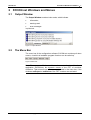


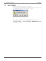


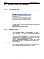
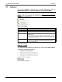


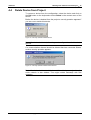


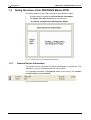

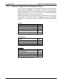
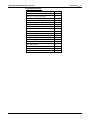


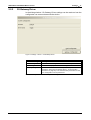
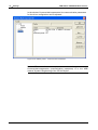
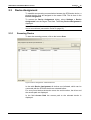
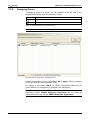
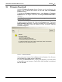

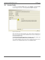


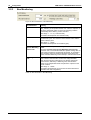

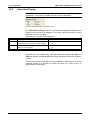

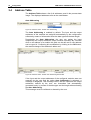
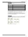


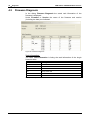


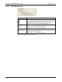
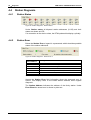
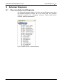
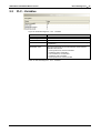
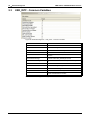
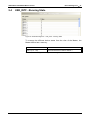
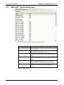
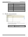
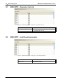

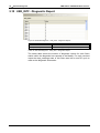

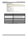


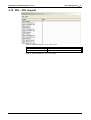


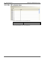
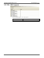


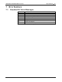
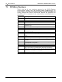
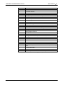
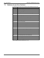

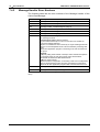

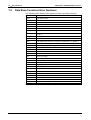
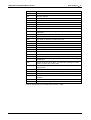
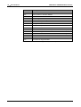


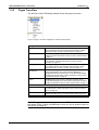


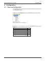

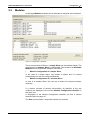


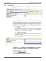

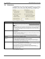
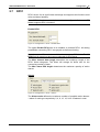
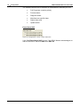
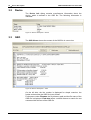

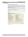
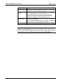
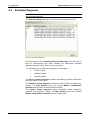


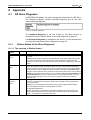

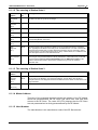
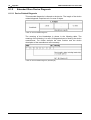
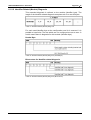

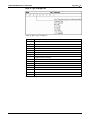
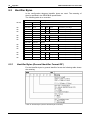
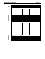

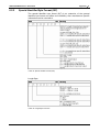
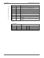


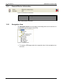


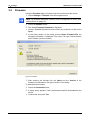

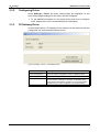
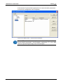
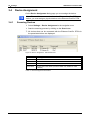
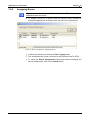

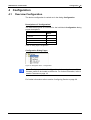
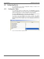
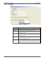
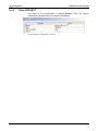

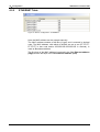
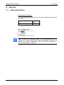

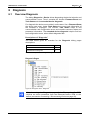
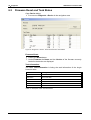
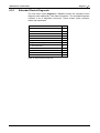

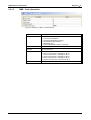
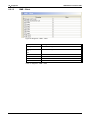
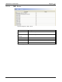
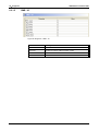

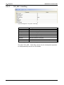


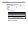


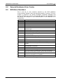


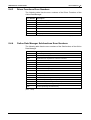

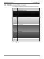
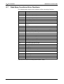
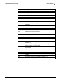
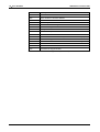


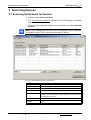

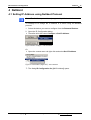
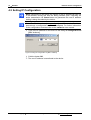

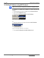
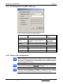


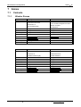
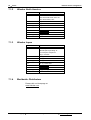


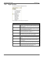

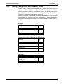

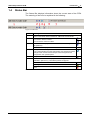


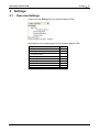
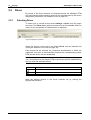
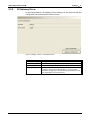

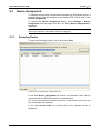


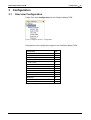

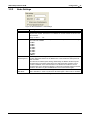
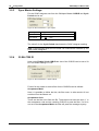
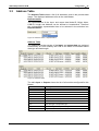

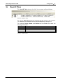

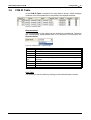

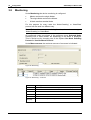
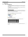
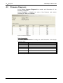


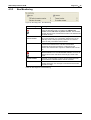
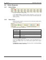

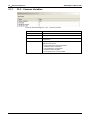
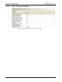
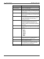
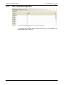
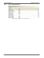
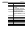
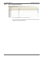
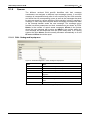

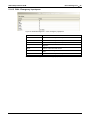
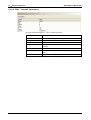
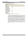
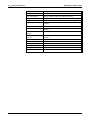


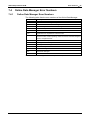
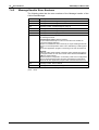
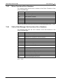


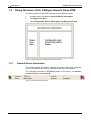

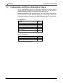


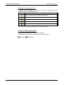


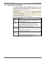
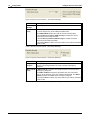
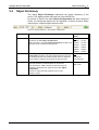
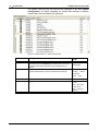


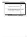
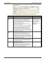
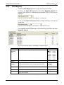

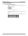
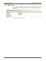
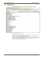


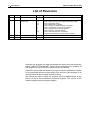

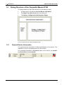
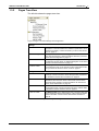
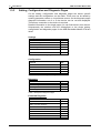
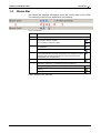


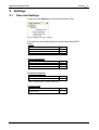


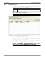

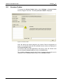

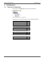


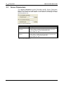


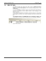


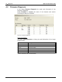
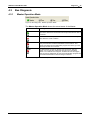


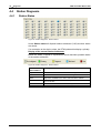

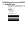
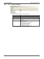
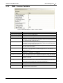
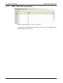

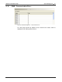
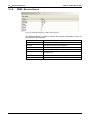


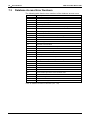


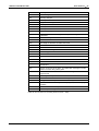
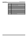


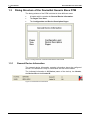
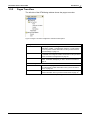


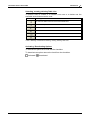

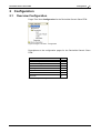

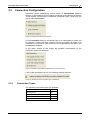
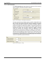
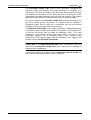
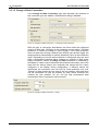

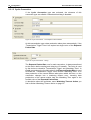
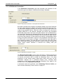

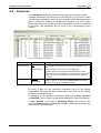

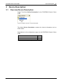

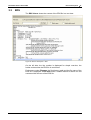


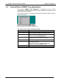
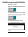


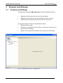
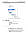


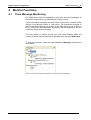

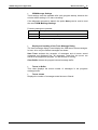


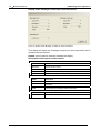
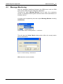

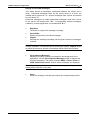


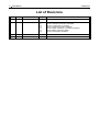


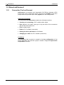
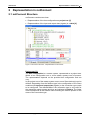


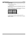
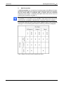
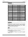
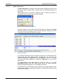


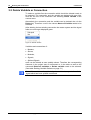


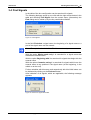

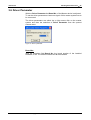


![() [IT] LK/S 4.2](http://vs1.manualzilla.com/store/data/006135181_1-b116a464f76fc09be64d6bd073b26233-150x150.png)