1
B201S/B202S
3U VMEbus
Carrier Boards
for M-Modules
20B201S00 E4
User Manual
1HXZLHGHU6WUDH
'1UQEHUJ
3KRQH
)D[
(0DLOLQIR#PHQGH
:::ZZZPHQGH
,62FHUWLILHG
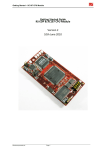
B201S/B202S - 3U VMEbus Carrier Boards for M-Modules
B201S/B202S - 3U VMEbus Carrier Boards for M-Modules
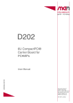
The B201S and B202S are M-Module carrier boards
for universal input/output applications on the
VMEbus. The boards require one slot each on the
VMEbus. M-Modules are screwed tightly on the
carrier board.
B201S
While B201S can carry one M-Module, the B202S is
slightly higher than standard 3U format, providing
enough space for two M-Modules while staying
compatible with VMEbus racks through
special guide rails already included in the
delivery.
B202S
The interrupt controller handles the M-Module’s interrupt priorities. Its
control and vector registers are user-programmable.
The B201S/B202S carrier boards have been designed for low power
consumption.
The use of high-speed CMOS components reduces heating of the
assembly, guaranteeing high reliability and long life.
Technical Data
VMEbus
• only one slot required on the VMEbus
• A24, A16, D16, D08 (E/O) slave
• D08 (O) interrupter
M-Modules
• B201S: one M-Module slot on the board
• B202S: two M-Module slots on the board
• M-Module characteristics: D08, D16, A08, INTA, INTC
Compatibility
• full compatibility with A201S (6U, 4 M-Module slots)
• functional compatibility with B201, B202 (2 M-Module slots) and A201N (4 MModule slots)
Peripheral Connections
• via front panel
MEN Mikro Elektronik GmbH
20B201S00 E4
2
Technical Data
Electrical Specifications
• supply voltage/power consumption:
- B201S: +5V (+5%, -0%) @ 350mA typ. (without M-Modules)
- B202S: +5V (+5%, -0%) @ 320mA typ. (without M-Modules)
• MTBF: 52,000h @ 50°C
Mechanical Specifications
• B201S:
- dimensions: standard single Eurocard, 100mm x 160mm
- front panel: aluminum with 1 handle, cut-out for front connector of M-Module
- weight: 108g
• B202S:
- dimensions: 110mm x 155mm
- front panel: aluminum without handles, cut-outs for front connectors of 2 MModules
- weight: 102g (without M-Modules)
Environmental Specifications
• temperature range (operation): 0..+60°C (industrial temperature range on
request)
• temperature range (storage): -40..+85°C
• relative humidity range (operation): max. 95% non-condensing
• relative humidity range (storage): max. 95% non-condensing
• altitude: -300m to + 3,000m
• shock: 15g/0.33ms, 6g/6ms
• vibration: 1g/5..2,000Hz
Safety
• PCB manufactured with a flammability rating of 94V-0 by UL recognized manufacturers
EMC
• tested according to IEC1000-4-2 (ESD) and IEC1000-4-4 (burst) with regard to
CE conformity
Software Support
• M-Module drivers for WindowsNT, VxWorks, OS-9 as supported
MEN Mikro Elektronik GmbH
20B201S00 E4
3
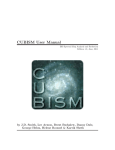
Block Diagram
Block Diagram
VMEbus Bus
Front-Panel I/O
Control Bus
Address Bus
Data Bus
VMEbus Interface/
Interrupt Controller
M-Module
M-Module
Ordering Information
Standard Hardware
01B201S00 B201S VMEbus 3U, A24/A16/D16, for one M-Module
01B202S00 B202S VMEbus 3U, A24/A16/D16, for two M-Modules, incl. guide
rails for rack installation
Accessories
05M000-15 10 snap-in front panel covers for M-Module cut-outs at front panels
05M000-17 25 mounting screw sets to fix M-Modules on carrier boards
User Manuals
20B201S00 B201S/B202S user manual, available for free download at
www.men.de
MEN Mikro Elektronik GmbH
20B201S00 E4
4
About this Document
About this Document
This user manual describes the hardware functions of the boards, connection of
peripheral devices and integration into a system. It also provides additional
information for special applications and configurations of the boards.
The manual does not include detailed information on individual components (data
sheets etc.). A list of literature is given in the appendix.
Unless explicitly stated, the name "B201S" refers both to the B201S and B202S
M-Module carrier boards in this user manual.
History
Edition
Description
Technical Content
Date of Issue
E1
First edition
Jonny Speckner
1994-11-25
E2
Second edition
Jonny Speckner
1995-12-04
E3
Third edition
Jonny Speckner
1998-07-06
E4
Fourth edition, B201S and Thomas Eckert
B202S in one user manual
2000-12-19
Conventions
!
italics
bold
hyperlink
This sign marks important notes or warnings concerning proper functionality of the
product described in this document. You should read them in any case.
Folder and file names are printed in italics.
Bold type is used for emphasis.
Hyperlinks are printed in blue color.
The globe will show you where hyperlinks lead directly to the Internet, so you can
look for the latest information online.
0xFF
Hexadecimal numbers are preceded by "0x", which is the usual C-language
convention, and are printed in a monospace type, e.g. 0x00FFFF.
/IRQ
Signal names preceded by a slash ("/") indicate that this signal is either active low or
that it becomes active at a falling edge.
in/out
Signal directions in signal mnemonics tables generally refer to the corresponding
board or component, "in" meaning "to the board or component", "out" meaning
"coming from it".
Vertical lines on the outer margin signal technical changes to the previous edition of
the document.
MEN Mikro Elektronik GmbH
20B201S00 E4
5
About this Document
MEN reserves the right to make changes without further notice to any products herein. MEN makes no warranty, representation or guarantee
regarding the suitability of its products for any particular purpose, nor does MEN assume any liability arising out of the application or use of
any product or circuit, and specifically disclaims any and all liability, including without limitation consequential or incidental damages.
"Typical" parameters can and do vary in different applications. All operating parameters, including "Typicals" must be validated for each
customer application by customer's technical experts.
MEN does not convey any license under its patent rights nor the rights of others.
MEN products are not designed, intended, or authorized for use as components in systems intended for surgical implant into the body, or other
applications intended to support or sustain life, or for any other application in which the failure of the MEN product could create a situation
where personal injury or death may occur. Should Buyer purchase or use MEN products for any such unintended or unauthorized application,
Buyer shall indemnify and hold MEN and its officers, employees, subsidiaries, affiliates, and distributors harmless against all claims, costs,
damages, and expenses, and reasonable attorney fees arising out of, directly or indirectly, any claim of personal injury or death associated with
such unintended or unauthorized use, even if such claim alleges that MEN was negligent regarding the design or manufacture of the part.
All brand or product names are trademarks or registered trademarks of their respective holders.
Information in this document has been carefully checked and is believed to be accurate as of the date of publication; however, no responsibility
is assumed for inaccuracies. MEN will not be liable for any consequential or incidental damages arising from reliance on the accuracy of this
document. The information contained herein is subject to change without notice.
Copyright © 2000 MEN Mikro Elektronik GmbH. All rights reserved.
MEN Mikro Elektronik GmbH
20B201S00 E4
6
Contents
Contents
1 Getting Started . . . . . . . . . . . . . . . . . . . . . . . . . . . . . . . . . . . . . . . . . . . . . . . . . 9
1.1 Map of the Board. . . . . . . . . . . . . . . . . . . . . . . . . . . . . . . . . . . . . . . . . . 9
1.2 Installation Check List. . . . . . . . . . . . . . . . . . . . . . . . . . . . . . . . . . . . . 11
1.3 Installing M-Modules . . . . . . . . . . . . . . . . . . . . . . . . . . . . . . . . . . . . . 12
1.3.1
Installing an M-Module on B201S . . . . . . . . . . . . . . . . . . . . 12
1.3.2
Installing an M-Module on B202S . . . . . . . . . . . . . . . . . . . . 13
1.4 Installing Driver Software . . . . . . . . . . . . . . . . . . . . . . . . . . . . . . . . . . 14
2 Address Organization . . . . . . . . . . . . . . . . . . . . . . . . . . . . . . . . . . . . . . . . . . . 15
3 Functional Description . . . . . . . . . . . . . . . . . . . . . . . . . . . . . . . . . . . . . . . . . .
3.1 Power Supply. . . . . . . . . . . . . . . . . . . . . . . . . . . . . . . . . . . . . . . . . . . .
3.2 VMEbus Interface . . . . . . . . . . . . . . . . . . . . . . . . . . . . . . . . . . . . . . . .
3.2.1
Slave Interface. . . . . . . . . . . . . . . . . . . . . . . . . . . . . . . . . . . .
3.2.2
Interrupter . . . . . . . . . . . . . . . . . . . . . . . . . . . . . . . . . . . . . . .
3.2.3
VMEbus Connector P1 . . . . . . . . . . . . . . . . . . . . . . . . . . . . .
3.3 M-Module Interfaces . . . . . . . . . . . . . . . . . . . . . . . . . . . . . . . . . . . . . .
3.3.1
M-Module Connectors . . . . . . . . . . . . . . . . . . . . . . . . . . . . .
3.4 Interrupt Controller . . . . . . . . . . . . . . . . . . . . . . . . . . . . . . . . . . . . . . .
3.4.1
Registers of the Controller . . . . . . . . . . . . . . . . . . . . . . . . . .
3.4.2
Power-Up/Reset Behavior. . . . . . . . . . . . . . . . . . . . . . . . . . .
16
16
16
16
18
19
20
20
21
21
22
4 Appendix . . . . . . . . . . . . . . . . . . . . . . . . . . . . . . . . . . . . . . . . . . . . . . . . . . . . .
4.1 Literature and WWW Resources. . . . . . . . . . . . . . . . . . . . . . . . . . . . .
4.2 Board Revisions. . . . . . . . . . . . . . . . . . . . . . . . . . . . . . . . . . . . . . . . . .
4.3 Component Plans. . . . . . . . . . . . . . . . . . . . . . . . . . . . . . . . . . . . . . . . .
23
23
23
24
MEN Mikro Elektronik GmbH
20B201S00 E4
7
Contents
Figures
Figure 1. Map of the Board - B201S - Top View . . . . . . . . . . . . . . . . . . . . . . . . . 9
Figure 2. Map of the Board - B202S - Top View . . . . . . . . . . . . . . . . . . . . . . . . 10
Figure 3. Installing an M-Module on B201S . . . . . . . . . . . . . . . . . . . . . . . . . . . . 12
Figure 4. Installing an M-Module on B202S . . . . . . . . . . . . . . . . . . . . . . . . . . . . 13
Figure 5. Setting the Base Address on B201S - Default (A24) . . . . . . . . . . . . . . 17
Figure 6. Setting the Base Address on B201S - Example (A16) . . . . . . . . . . . . . 17
Figure 7. Setting the Base Address on B202S - Default (A24) . . . . . . . . . . . . . . 17
Figure 8. Setting the Base Address on B202S - Example (A16) . . . . . . . . . . . . . 18
Figure 9. Component Plan of B201S Hardware Revision 02 . . . . . . . . . . . . . . . 24
Figure 10. Component Plan of B202S Hardware Revision 00 . . . . . . . . . . . . . . . 25
Tables
Table 1.
Table 2.
Table 3.
Table 4.
Table 5.
Table 6.
MEN Mikro Elektronik GmbH
20B201S00 E4
Address Map. . . . . . . . . . . . . . . . . . . . . . . . . . . . . . . . . . . . . . . . . . . . .
Address Modifier Codes Permitted on A201S . . . . . . . . . . . . . . . . . . .
Pin Assignment of the 96-Pin VMEbus P1 Connector. . . . . . . . . . . . .
Pin Assignment of the 40-Pin M-Module Plug Connector. . . . . . . . . .
Table of Hardware Revisions - B201S . . . . . . . . . . . . . . . . . . . . . . . . .
Table of Hardware Revisions - B202S . . . . . . . . . . . . . . . . . . . . . . . . .
15
18
19
20
23
23
8
Getting Started
1
Getting Started
This chapter will give an overview of the carrier boards and some hints for first
installation in a system as a "check list".
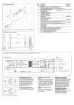
1.1
Map of the Board
Holes for MModule Mounting
Screws
M-Module 0
40-pin plug
connector
VMEbus P1
Figure 1. Map of the Board - B201S - Top View
DIL Switches for Setting the
Base Address
MEN Mikro Elektronik GmbH
20B201S00 E4
9
Getting Started
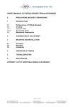
Figure 2. Map of the Board - B202S - Top View
M-Module 1
40-pin plug
connector
VMEbus P1
Front Panel
Mounting Screws
DIL Switches for Setting the
Base Address
Front Panel
Mounting Screws
MEN Mikro Elektronik GmbH
20B201S00 E4
M-Module 0
40-pin plug
connector
10
Getting Started
1.2
Installation Check List
You can use the following hints and "check list" to install the carrier board into a
VMEbus system for the first time and to test proper functioning of the board.
The B201S has an A24/D16 or A16/D16 VMEbus slave interface. If it is required
for the board to issue an interrupt via the bus, then the daisy-chain must be
established through to the B201S.
!
The carrier board is completely trimmed on delivery. Perform the following
procedure without an M-Module installed!
; Power-down the system.
; The board is set for A24 accesses, the base address being 0xE00000. This
base address is set using DIL switches. It may be necessary to set it to an
address with which the master can access the board in A24/D16 mode.
(If you have to change the base address, please refer to Chapter 3.2.1.1 Setting
the Base Address on page 16.)
; Insert the B201S into your VMEbus system, making sure that the VMEbus connectors are properly aligned.
!
Note: The B202S is slightly higher than standard 3U Eurocard format, so that it
can accommodate two M-Modules. Its dimensions are 110mm by
155mm. Because of this deviation you need special guide rails to install
the B202S in your 3U VMEbus system, which are included in the standard B202S delivery. The rails are also available as a standard product
directly from Schroff (guide rail for 4.4" cards), order no. 60817-038.
; Power-up the system.
; After power-up, load a suitable debugger.
; First, attempt to perform a read-word access to the base address plus 0x100,
(i.e. 0xE00100 if the base address was not altered).
With 32-bit masters it may be necessary to load a register on the master board
to set the access mode. In any case you should be aware of the contents of the
high-order byte of the 32-bit address. For instance, access may require using
address 0xFFE00100 or 0xFCE00100.
; If a bus error occurs while you are attempting to read, check if the base address
is set correctly and whether it is possible for the master to access the VMEbus
at all at the selected address and using the correct mode. Then try again.
; Now attempt to perform a word access to the base address plus 0x102. Again,
no bus error should occur. Write accesses to this memory location should be
successful for the right half of the word. For instance, if 0x55 is written to the
register it should be possible to read 0xxx55.
; You must have completed this test successfully before you begin to integrate an
M-Module into the system (see Chapter 1.3 Installing M-Modules on page 12
and description in the respective M-Module manual).
Note: Interrupts cannot be tested in this simple fashion.
MEN Mikro Elektronik GmbH
20B201S00 E4
11
Getting Started
1.3
Installing M-Modules
1.3.1
Installing an M-Module on B201S
Perform the following steps to install an M-Module:
; Hold the M-Module over the target slot of the B201S with the component sides
facing each other.
; Put the M-Module’s front connector through the front panel slot, holding the
M-Module at a 45° angle.
; Align the 40-pin connectors of the M-Module and carrier board.
; Press the M-Module carefully but firmly on the B201S, making sure that the
connectors are properly linked.
; Turn the B201S upside down and use four M-Module mounting screws to fasten the M-Module on the solder side of the B201S.
Note: You can order suitable mounting screws from MEN, see Chapter Ordering
Information on page 4.
Figure 3. Installing an M-Module on B201S
M-Module
Mounting Bolt
40-pin connector
B201S
M3x6 cross-recess
countersink-head
screw (DIN 965)
MEN Mikro Elektronik GmbH
20B201S00 E4
M3x6 slotted panhead screw
(plastics) (DIN 85)
12
Getting Started
1.3.2
Installing an M-Module on B202S
Perform the following steps to install an M-Module:
; Remove the four front panel mounting screws and thus the front panel itself.
(See Figure 2, Map of the Board - B202S - Top View, on page 10.)
; Hold the M-Module over the target slot of the B202S with the component sides
facing each other.
; Align the 40-pin connectors of the M-Module and carrier board.
; Press the M-Module carefully but firmly on the B202S, making sure that the
connectors are properly linked.
; Turn the B202S upside down and use four M-Module mounting screws to fasten both the M-Module and the carrier board front panel on the solder side of
the B202S.
Note: You can order suitable mounting screws from MEN, see Chapter Ordering
Information on page 4.
Figure 4. Installing an M-Module on B202S
M-Module
M-Module
Mounting Bolt
40-pin connector
B202S
M3x6 cross-recess
countersink-head
screw (DIN 965)
MEN Mikro Elektronik GmbH
20B201S00 E4
M3x6 slotted panhead screw
(plastics) (DIN 85)
13
Getting Started
1.4
Installing Driver Software
For a detailed description on how to install driver software please refer to the
M-Module’s software user manual.
MEN Mikro Elektronik GmbH
20B201S00 E4
14
Address Organization
2
Address Organization
As mentioned above, the B201S occupies an address space of 0x800 bytes on the
VMEbus. These 0x800 bytes are divided into four identical parts. Each 0x200byte part is assigned to one M-Module slot. 0x100 bytes are used for addressing
the M-Module itself. The remaining 0x100 bytes are used to address a part of the
interrupt controller. Since the B201S has only one M-Module slot and B202S has
two slots, 0x400 and 0x600 bytes remain unused, respectively, but ensure full
compatibility with the A201S board (see grey text in the address map below).
Table 1. Address Map
Offset Address
Function
0x000..0x0FF
M-Module
0x101
Control Register
0x103
Vector Register
0x200..0x2FF
M-Module (only B202S)
0x301
Control Register (only B202S)
0x303
Vector Register (only B202S)
0x400..0x4FF
M-Module
0x501
Control Register
0x503
Vector Register
0x600..0x6FF
M-Module
0x701
Control Register
0x703
Vector Register
M-Module
0
1
2
3
The base address base of an M-Module is calculated by the formula
base = B201Sbase + modslot ⋅ 0x200
M-Module base address
base
B201Sbase base address of B201S
M-Module slot number on B201S
modslot
Example
The base address set for the B201S is 0xE00000. An M-Module is plugged into
M-Module slot 2. The M-Module base address is then
0xE00000 + 2 ⋅ 0x200 = 0xE00200
For instance, if we are dealing with a 32-bit master which addresses the standard
address area at 0xFFxxxxxx, then the M-Module at address 0xFFE00200 is
selected. The corresponding interrupt control register then has address
0xFFE00301.
MEN Mikro Elektronik GmbH
20B201S00 E4
15
Functional Description
3
Functional Description
3.1
Power Supply
The 5V power supply from the VMEbus is sufficient for the carrier board. Some
M-Modules (e.g. serial interfaces) need ±12V as well.
3.2
VMEbus Interface
3.2.1
Slave Interface
The B201S board is equipped with an A16/A24/D16 slave interface, i.e, only cycles
with standard (24-bit) addresses and short (16-bit) address range are supported. For
accesses from the VMEbus, the slave recognizes this type of cycle on the basis of
the address modifier lines. The data bus interface of the B201S complies with the
D16 specification. However, some M-Modules with a data bus width of only 8 bits
permit only D08(O) accesses. The slave recognizes this type of access by the state
of lines DS0*, DS1*, LWORD* and A1. The B201S will operate with masters
which support so-called "address pipelining". The access time on the B201S
depends on the M-Module concerned. DTACK* is generated 120ns after AS* at the
earliest. The maximum time is limited to 10µs - in line with the M-Module
Standard.
3.2.1.1
Setting the Base Address
The B201S occupies an area of 0x800 in the address space. Identical quarters of
this - that is 0x200 - are reserved for four M-Modules together with the interrupt
handler. Since the B201S supports only one M-Module and B202S supports two
M-Modules, an address range of 0x400 or 0x600 remains unused, respectively.
This ensures full compatibility with the A201S, which has four M-Module slots.
The base address of the B201S can be varied in increments of 0x800 within the
whole A16 or A24 address range. It is set using DIL switches. There is one switch
for each address bit from A11 to A23. If the switch is "on", the corresponding
address bit is compared with 0. If the switch is "off", it is compared with 1. If the
address is the same as the switch setting (taking address modifiers into account), a
"select" signal for the board is generated. In the short address range, the switches
corresponding to A16 to A23 are ignored.
The selection between short address range and standard address range is made by
the SRT switch. If SRT is switched on, short accesses are possible; if SRT is
switched off, standard accesses are allowed.
!
Note: Please note that on B202S the DIL switches are not accessible anymore once
you have installed M-Module 0! On B201S the DIL switches remain accessible even with the M-Module installed. (C.f. Chapter 1.1 Map of the Board on
page 9.)
MEN Mikro Elektronik GmbH
20B201S00 E4
16
Functional Description
Figure 5. Setting the Base Address on B201S - Default (A24)
Default Mode
A24
8
A23
A15
7
A22
A14
6
A21
A13
5
A20
A12
4
A19
A11
3
A18
not used
2
A17
not used
1
A16
SRT
Default Base Address
0xE00000
1
2
3
4
5
6
7
8
on
0
on
0
off
1
off
1
Figure 6. Setting the Base Address on B201S - Example (A16)
Example Address Mode
A16
SRT
not used
not used
A11
A12
A13
A14
A15
A16
A17
A18
A19
A20
A21
A22
A23
Base Address
0x4000
1
2
3
4
5
6
7
8
1
2
3
4
5
6
7
8
on
0
on
0
off
1
off
1
Figure 7. Setting the Base Address on B202S - Default (A24)
Default Mode
A24
Default Base Address
0xE00000
MEN Mikro Elektronik GmbH
20B201S00 E4
8
7
6
5
4
3
2
1
8
7
6
5
4
3
2
1
A16
A15
A14
A13
A12
A11
not used
not used
SRT
on
A17
0
A18
on
A19
0
A20
off
A21
1
A22
off
A23
1
17
Functional Description
Figure 8. Setting the Base Address on B202S - Example (A16)
Example Address Mode
A16
Base Address
0x4000
1
3.2.1.2
2
1
8
7
6
5
4
3
2
1
A15
A14
A13
A12
A11
not used
not used
SRT
on
3
A16
A21
0
4
A17
A22
on
5
A18
6
off
A19
7
1
A20
8
A23
0
off
Address Modifiers
The VMEbus has 6 "address modifier" lines. These lines allow the master to transfer
additional binary information to the slave during a data transfer cycle. The lines are
used to divide the address space of the VMEbus into several classes. The following
codes are permitted for the A201S:
Table 2. Address Modifier Codes Permitted on A201S
HEX
Code
AM
5
4
Function
SRT
3
1
0
3d, 39
H H H
L
H Standard supervisory and non-privileged data access
off
2d, 29
H
L
H Short supervisory and non-privileged
data access
on
L
H
As mentioned above, SRT specifies standard or short access. The factory setting
allows supervisor-mode and nonprivileged-mode access. Other address modes are
possible in principle. They are specified in a programmable FLEX Logic
component.
3.2.2
Interrupter
The interrupter has been implemented using a FLEX Logic IC. This chip permits
interrupts to be issued at a programmable level. The B201S is a D08(O) interrupter.
This means that the interrupter outputs status information on D0..D7 during an
interrupt acknowledge cycle. Depending on which M-Module generates the
interrupt it can be an RORA (= Release On Register Access) or an ROAK (=
Release On Acknowledge) interrupt. This means that the interrupt request is reset
either by the interrupt acknowledge cycle itself or by access to a specific register.
Since the interrupter is fully programmable, it is not necessary to set any jumpers or
DIL switches.
MEN Mikro Elektronik GmbH
20B201S00 E4
18
Functional Description
3.2.3
VMEbus Connector P1
Connector types:
• 96-pin type-C plug connector according to DIN41612/MIL-C-55302/IEC603-2
• mating connector:
type-C 96-pin receptacle according to DIN41612/MIL-C-55302/IEC603-2,
available with solder/wire-wrap pins, for hand-soldering connection or for insulation piercing connection (IDC)
Table 3. Pin Assignment of the 96-Pin VMEbus P1 Connector
ABC
1
32
MEN Mikro Elektronik GmbH
20B201S00 E4
A
B
C
D0
-
D8
D1
-
D9
D2
-
D10
D3
-
D11
D4
-
D12
D5
-
D13
D6
-
D14
D7
-
D15
GND
-
GND
SYSCLK
-
-
GND
-
-
/DS1
-
/SYSRST
/DS0
-
/LWORD
/WRITE
-
AM5
GND
-
A23
/DTACK
AM0
A22
GND
AM1
A21
/AS
AM2
A20
GND
AM3
A19
/IACK
GND
A18
/IACKIN
-
A17
/IACKOUT
-
A16
AM4
GND
A15
A7
/IRQ7
A14
A6
/IRQ6
A13
A5
/IRQ5
A12
A4
/IRQ4
A11
A3
/IRQ3
A10
A2
/IRQ2
A9
A1
/IRQ1
A8
-12V
-
+12V
+5V
+5V
+5V
19
Functional Description
3.3
M-Module Interfaces
One M-Module can be installed on the B201S, and two M-Modules on B202S.
Peripheral equipment may be connected at the front using the front connector of the
M-Module.
3.3.1
M-Module Connectors
The signals from the carrier board are fed to the M-Module via a 40-pin plug
connector. This plug connector corresponds to a receptacle connector on the
M-Module.
Connector types:
• two 20-pin plugs, 2.54mm pitch, square pins ∅ 0.635mm gold
• mating connector:
two 20-pin receptacles, high-precision, 2.54mm pitch, for square pins ∅
0.635mm gold, 6.9mm height
Table 4. Pin Assignment of the 40-Pin M-Module Plug Connector
A B
1
20
MEN Mikro Elektronik GmbH
20B201S00 E4
A
B
/CS
GND
A01
+5V
A02
+12V
A03
-12V
A04
GND
A05
-
A06
-
A07
GND12V
D08
D00
D09
D01
D10
D02
D11
D03
D12
D04
D13
D05
D14
D06
D15
D07
DS1
DS0
/DTACK
/WRITE
/IACK
/IRQ
/RESET
SYSCLK
20
Functional Description
3.4
Interrupt Controller
The FLEX Logic chip handles local interrupt sources with the VMEbus. It supports
all signals used for the VMEbus interrupt protocol. Interrupt vectors from the local
source of the interrupt can be passed on, and the chip also provides the capability of
passing a pre-programmed vector. Eight internal registers (four status registers and
four vector registers) are provided for general use.
3.4.1
Registers of the Controller
The interrupt controller contains eight programmable read-write registers. The four
control registers control the activity of the chip, the other four are the vector
registers, which contain the vector information for the IACK cycle. One pair of
registers is allocated to the M-Module.
Control Registers (read/write)
7..6
5
4
3
-
X/IN
IRE
IRAC
2
1
0
L
X/IN external/internal
This bit governs behavior during an IACK cycle. If the X/IN bit is ’0’, the
chip replies with the /DTACK signal and the vector stored in its vector
register, i.e. it replies internally. If the X/IN bit is set, the M-Module has to
generate the vector and the /DTACK signal.
interrupt enable
This bit must be ’1’ to allow an interrupt to be generated at all. If this bit is
’0’, no interrupt is triggered on the VMEbus - even though an interrupt from
the M-Module is pending.
IRE
IRAC interrupt auto clear
If this bit is set, the IRE bit is cleared during an IACK cycle (in response to
this interrupt request) which disables the interrupt. In order to enable the
interrupt again, the IRE bit must be set again by writing to the control register.
interrupt level
These bits select the line on which the interrupt request is to be generated.
’111’ corresponds to IRQ7, ’110’ to IRQ6 etc. The code ’000’ disables
interrupt generation.
L
Vector Registers (read/write)
7
6
5
4
3
2
1
0
V7
V6
V5
V4
V3
V2
V1
V0
V7..V0
MEN Mikro Elektronik GmbH
20B201S00 E4
interrupt vectors
If the X/IN bit is ’0’, this vector is generated at D0..D7 during the IACK
cycle.
21
Functional Description
3.4.2
Power-Up/Reset Behavior
At power-up, the control registers are all loaded with 0x00, the vector registers are
set to the value 0x0F. This value corresponds to the 68000 vector for an
uninitialized interrupt.
After a reset only the interrupt level is set to zero.
MEN Mikro Elektronik GmbH
20B201S00 E4
22
Appendix
4
Appendix
4.1
Literature and WWW Resources
• M-Module Standard:
ANSI/VITA 12-1996, M-Module Specification;
VMEbus International Trade Association
7825 E. Gelding Dr., Ste. 104,
Scottsdale, AZ 85260
WWW: http://www.vita.com
4.2
Board Revisions
Table 5. Table of Hardware Revisions - B201S
Revision
Comment
Restrictions
00.xx
first revision released
none known
01.xx
second revision
none known
02.xx
third revision
none known
Table 6. Table of Hardware Revisions - B202S
Revision
00.xx
MEN Mikro Elektronik GmbH
20B201S00 E4
Comment
first revision released
Restrictions
none known
23
Appendix
4.3
Component Plans
Figure 9. Component Plan of B201S Hardware Revision 02
MEN Mikro Elektronik GmbH
20B201S00 E4
24
Appendix
Figure 10. Component Plan of B202S Hardware Revision 00
MEN Mikro Elektronik GmbH
20B201S00 E4
25
You can request the circuit diagrams for the current revision of the product described in this
manual by completely filling out and signing the following non-disclosure agreement.
Please send the agreement to MEN by mail. We will send you the circuit diagrams along with a
copy of the completely signed agreement by return mail.
MEN reserves the right to refuse sending of confidential information for any reason that MEN
may consider substantial.
Non-Disclosure Agreement
for Circuit Diagrams provided by MEN Mikro Elektronik GmbH
between
MEN Mikro Elektronik GmbH
Neuwieder Straße 7
D-90411 Nürnberg
(”MEN”)
and
____________________
____________________
____________________
____________________
(”Recipient”)
We confirm the following Agreement:
MEN
Recipient
Date:
______________________
Date:
______________________
Name:
______________________
Name:
______________________
Function:
______________________
Function:
______________________
Signature:
Signature:
____________________________________
____________________________________
The following Agreement is valid as of the date of MEN’s signature.
1HXZLHGHU6WUDH
'1UQEHUJ
3KRQH
)D[
(0DLOLQIR#PHQGH
:::ZZZPHQGH
Non-Disclosure Agreement for Circuit Diagrams page 1 of 2
,62FHUWLILHG
1
Subject
The subject of this Agreement is to protect all information contained in the circuit diagrams of the
following product:
Article Number:__________________ [filled out by recipient]
MEN provides the recipient with the circuit diagrams requested through this Agreement only for
information.
2
Responsibilities of MEN
Information in the circuit diagrams has been carefully checked and is believed to be accurate as
of the date of release; however, no responsibility is assumed for inaccuracies. MEN will not be liable for any consequential or incidental damages arising from reliance on the accuracy of the circuit diagrams. The information contained therein is subject to change without notice.
3
Responsibilities of Recipient
The recipient, obtaining confidential information from MEN because of this Agreement, is obliged
to protect this information.
The recipient will not pass on the circuit diagrams or parts thereof to third parties, neither to individuals nor to companies or other organizations, without the written permission by MEN. The circuit diagrams may only be passed to employees who need to know their content. The recipient
protects the confidential information obtained through the circuit diagrams in the same way as he
protects his own confidential information of the same kind.
4
Violation of Agreement
The recipient is liable for any damage arising from violation of one or several sections of this
Agreement. MEN has a right to claim damages amounting to the damage caused, at least to
DM 100,000.
5
Other Agreements
MEN reserves the right to pass on its circuit diagrams to other business relations to the extent
permitted by the Agreement.
Neither MEN nor the recipient acquire licenses for the right of intellectual possession of the other
party because of this Agreement.
This Agreement does not result in any obligation of the parties to purchase services or products
from the other party.
6
Validity of Agreement
The period after which MEN agrees not to assert claims against the recipient with respect to the
confidential information disclosed under this Agreement shall be _______ months [filled out by
MEN]. (Not less than twenty-four (24) nor more than sixty (60) months.)
7
General
If any provision of this Agreement is held to be invalid, such decision shall not affect the validity of
the remaining provisions and such provision shall be reformed to and only to the extent necessary to make it effective and legal.
This Agreement is only effective if signed by both parties.
Amendments to this Agreement can be adopted only in writing. There are no supplementary oral
agreements.
This Agreement shall be governed by German Law.
The court of jurisdiction shall be Nuremberg.
1HXZLHGHU6WUDH
'1UQEHUJ
3KRQH
)D[
(0DLOLQIR#PHQGH
:::ZZZPHQGH
Non-Disclosure Agreement for Circuit Diagrams page 2 of 2
,62FHUWLILHG
Fax Reply
Who you are...
Name
__________________________ Phone No.
__________________________
Company
__________________________ Fax No.
__________________________
Department __________________________ E-mail
__________________________
Use our online forms
at http://www.men.de
What we can do for you...
Product Support
Manual Feedback
Product Article No.
__________________
Manual Article No. __________________
Revision
__ __ . __ __ . __ __
Edition
If the product is a mezzanine module:
Carrier Article No.
__________________
Revision
__ __ . __ __ . __ __
E ___
Useful or awful?
very useful totally awful
Operating system
Usage
OS-9
I read the manual and decided to buy the
VxWorks
WindowsNT
other:
___________________________________
• Technical Support
• User Manuals
related product.
I read the manual when I got the product.
I refer to the manual only when I have
problems.
Your problems/comments...
1HXZLHGHU6WUDH
'1UQEHUJ
3KRQH
)D[
(0DLOLQIR#PHQGH
:::ZZZPHQGH
,62FHUWLILHG