1
HBAnyware® Utility
Version 3.2
User Manual
Last Updated August 7, 2007
Copyright© 2007 Emulex Corporation. All rights reserved worldwide. No part of this document may be reproduced
by any means nor translated to any electronic medium without the written consent of Emulex Corporation.
Information furnished by Emulex Corporation is believed to be accurate and reliable. However, no responsibility is
assumed by Emulex Corporation for its use; or for any infringements of patents or other rights of third parties which
may result from its use. No license is granted by implication or otherwise under any patent or patent rights of Emulex
Corporation.
Emulex, AutoPilot Installer, BlockGuard, cLAN, FabricStream, FibreSpy, Giganet, HBAnyware, InSpeed, IntraLink,
LightPulse, MultiPulse, SAN Insite, SBOD and Vixel are registered trademarks, and AutoPilot Manager, EZPilot,
SLI and VMPilot are trademarks of Emulex Corporation. All other brand or product names referenced herein are
trademarks or registered trademarks of their respective companies or organizations.
Emulex provides this manual "as is" without any warranty of any kind, either expressed or implied, including but not
limited to the implied warranties of merchantability or fitness for a particular purpose. Emulex Corporation may
make improvements and changes to the product described in this manual at any time and without any notice. Emulex
Corporation assumes no responsibility for its use, nor for any infringements of patents or other rights of third parties
that may result. Periodic changes are made to information contained herein; although these changes will be
incorporated into new editions of this manual, Emulex Corporation disclaims any undertaking to give notice of such
changes.
Last Updated August 7, 2007
HBAnyware User Manual
Page ii
HBAnyware ..............................................................................................1
Introduction.............................................................................................................. 1
Starting the HBAnyware Utility .......................................................................... 2
Starting HBAnyware with Web Launch ........................................................ 2
Starting the HBAnyware Security Configurator............................................ 2
Starting HBAnyware from the Command Line ............................................. 3
Changing Management Mode .......................................................................... 3
The HBAnyware Utility Window Element Definitions ......................................... 4
The Menu Bar ............................................................................................. 4
The Toolbar ................................................................................................. 4
The Toolbar Buttons .................................................................................... 5
The Discovery-Tree..................................................................................... 5
Property Tabs .............................................................................................. 6
Status Bar ................................................................................................... 7
Using the HBAnyware Utility Command-Line Interface...................................... 7
Using the CLI Client (Linux) ........................................................................ 7
Discovering HBAs.................................................................................................. 22
Configuring Discovery Settings ....................................................................... 23
Sorting HBA Information ........................................................................................ 24
Sort by Host Name .......................................................................................... 24
Sort by Fabric Address .................................................................................... 24
Sorting Local HBAs Only ................................................................................. 24
Viewing HBA Information ....................................................................................... 25
Viewing Discovery Information ........................................................................ 25
Discovery Information Field Definitions ..................................................... 25
Viewing Host Information................................................................................. 26
The Host Information Tab .......................................................................... 26
The Host Driver Parameters Tab ............................................................... 27
Viewing General HBA Attributes...................................................................... 28
Adapter Summary Field Definitions ........................................................... 28
Adapter Status Area Field Definitions........................................................ 29
Viewing Detailed HBA Information................................................................... 29
Adapter Details Field Definitions ............................................................... 30
Port Attributes Field Definitions ................................................................. 30
Loop Map Table Definitions ....................................................................... 31
Viewing Fabric Information .............................................................................. 31
Discovery Information Field Definitions ..................................................... 31
Viewing Target Information .............................................................................. 32
Target Information Field Definitions ........................................................... 32
Viewing LUN Information ................................................................................. 33
LUN Information Field Definitions.............................................................. 33
Viewing Port Statistics ..................................................................................... 34
Port Statistics Field Definitions .................................................................. 34
Viewing Firmware Information ......................................................................... 35
Firmware Field Definitions......................................................................... 36
Viewing Target Mapping ................................................................................. 37
Target Mapping Field Definitions ............................................................... 37
Resetting HBAs ..................................................................................................... 38
Updating Firmware ................................................................................................ 38
Prerequisites ............................................................................................. 38
HBAnyware User Manual
Page iii
Procedure ................................................................................................. 38
Updating Firmware (Batch Mode).................................................................... 40
Prerequisites ............................................................................................. 40
Procedure ................................................................................................. 41
Enabling or Disabling an HBA’s BIOS.............................................................. 42
Configuring the Driver............................................................................................ 44
Setting Driver Parameters ............................................................................... 44
Setting Driver Parameters for an HBA....................................................... 44
Setting Driver Parameters for a Host ........................................................ 46
Creating the Batch Mode Driver Parameters File ...................................... 47
Assigning Batch Mode Parameters to HBAs ............................................. 48
Driver Configuration for VMware ..................................................................... 49
Setting Topology.............................................................................................. 49
Mapping and Masking............................................................................................ 50
Automapping SCSI Devices ............................................................................ 50
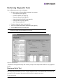
Performing Diagnostic Tests .................................................................................. 51
Running a Quick Test ...................................................................................... 51
Running a POST ............................................................................................. 52
Using Beaconing ............................................................................................. 52
Creating Diagnostic Dumps ............................................................................. 52
Displaying PCI Registers and Wakeup Information ......................................... 53
Running Advanced Diagnostic Tests ............................................................... 54
Running Loopback Tests ................................................................................. 55
Running End-to-End (ECHO) Tests ................................................................. 56
Saving the Log File.......................................................................................... 57
Out-of-Band SAN Management ............................................................................ 58
Adding a Single Host ....................................................................................... 58
Adding a Range of Hosts................................................................................. 59
Removing Hosts .............................................................................................. 60
HBAnyware Security.............................................................................................. 61
Introduction ..................................................................................................... 61
Starting the HBAnyware Security Configurator ................................................ 61
Prerequisites ............................................................................................. 61
Procedure ................................................................................................. 62
Running the Configurator for the First Time/Creating the ACG........................ 62
Designating a Master Security Client............................................................... 63
Access Control Groups.................................................................................... 63
Introduction ............................................................................................... 63
Access Control Group Tab on the MSC..................................................... 63
Access Control Group Tab on a Non-MSC ................................................ 64
ACG Icons................................................................................................. 64
Run the Configurator for the First Time/Create the ACG ........................... 65
Adding a Server to the ACG...................................................................... 65
Deleting a Server from the ACG................................................................ 66
Removing Security from all Servers in the ACG........................................ 66
Generating New Security Keys ................................................................. 66
Restoring the ACG to Its Last Saved Configuration .................................. 67
Accessing a Switch ................................................................................... 67
Access Sub-Groups......................................................................................... 67
Introduction ............................................................................................... 67
ASG Icons ................................................................................................. 68
HBAnyware User Manual
Page iv
Creating an ASG ....................................................................................... 68
Reserved Indices - Examples.................................................................... 69
Adding a Server to an ASG ....................................................................... 70
Deleting an ASG ....................................................................................... 70
Restoring an ASG to Its Last Saved Configuration.................................... 70
Editing an ASG ......................................................................................... 70
About Offline ASGs ................................................................................... 72
Backup Masters............................................................................................... 72
Introduction ............................................................................................... 72
Backup Master Eligible Systems ............................................................... 73
Backup Master Tab and Controls .............................................................. 73
Creating a Backup Master......................................................................... 74
Reassigning a Backup Master as the New MSC from the Old MSC.......... 74
Reassigning a Backup Master as the New MSC
from the Backup Master ............................................................................ 75
HBAnyware User Manual
Page v
HBAnyware
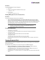
Introduction
Emulex drivers have many options that you can modify to provide for different behavior. You can change
these options using the HBAnyware® utility. The HBAnyware utility is client/server based and provides
'remote' configuration capability to other host platforms running the HBAnyware utility. This remote
configuration capability can be provided either "in-band" (host systems on the same FC SAN) or "out-ofband" (from IP addresses of remote machines). The HBAnyware utility also enables the local and “inband” discovery of Emulex and OEM branded Emulex host bus adapters (HBAs).
The HBAnyware Web Launch feature enables you to download and launch the HBAnyware user
interface by specifying the URL of a server that is hosting the HBAnyware Web Launch software. The
client machine from which the request is being made does not need the HBAnyware package or even an
installed Emulex HBA. You only need a standard web browser, or some other application capable of
making HTTP requests. You do not even need the Java runtime as that too will be automatically
downloaded if it is not already present.
Note: Only the HBAnyware Web Launch GUI is being exported to the requesting client. All
HBA discovery and remote management operations are performed by resources
running on the remote host that served up the GUI component. Therefore, the SAN
"view" displayed by the GUI is not from the perspective of the client running the GUI,
but rather from the perspective of the host from which this GUI was retrieved.
Note: The Linux 2.6 SCSI midlayer provides a number of additional services compared to
earlier Linux 2.4 kernels. For an overview of 2.6 SCSI and Emulex driver changes,
see the white paper on the Linux section of the Emulex Web site.
•
The HBAnyware utility is a user-friendly graphical environment. Use the HBAnyware utility to do
any of the following:
•
Discover local and remote hosts, host bus adapters (HBAs), targets and LUNs
•
Enables the local and “in-band” discovery of Emulex and OEM branded Emulex HBAs
•
Reset HBAs
•
Set HBA driver parameters
•
Set driver parameters simultaneously to multiple HBAs using Batch Update
•
Set global driver parameters to HBAs
•
Update firmware on a single HBA or multiple HBAs using Batch Update
•
Enable or disable the Boot BIOS
•
Run diagnostic tests on HBAs
•
Manage out-of-band HBAs
•
Manage local and in-band remote HBAs
•
Locate HBAs using beaconing
•
Launch HBAnyware directly from your Web browser
HBAnyware User Manual
Page 1
Note: Remote in-band capabilities of the HBAnyware utility are subject to fabric zoning
configuration. Remote hosts you want to discover and manage using the HBAnyware
utility must be in the same zone or discovered and managed out-of-band through an
Ethernet connection.
Starting the HBAnyware Utility
Note: The HBAnyware utility can only discover and manage remote HBAs on hosts running
the HBAnyware utility’s elxhbamgr daemon.
To start HBAnyware:
Note: For in-band management, remote capabilities of the HBAnyware utility are subject to
fabric zoning configuration. Remote hosts you want to discover and manage using the
HBAnyware utility must be in the same zone.
1. su to ‘root’.
2. Run the script:
/usr/sbin/hbanyware/hbanyware
Starting HBAnyware with Web Launch
After the HBAnyware Web Launch software has been installed and the Web Launch server has been
initialized, you can launch the HBAnyware utility directly with your Web browser.
To launch the HBAnyware utility with your Web browser:
1. Open your Web browser.
2. Enter the URL of an HBAnyware.jnlp file. Make sure that the URL specifies a remote server
which has the HBAnyware Web Launch software installed and running. For example:
http://138.239.20.30/hbanyware.jnlp
Note: If the browser window displays “Emulex Corporation HBAnyware Demo of
HBAnyware WebStart web n.n.n.n ...” when attempting to start HBAnyware with Web
Launch, exit the browser and restart it. HBAnyware with Web launch should start
successfully.
Uninstall all non-essential versions of the Java Runtime. HBAnyware Web Launch
services require that only a single version of the Java Runtime be installed on the
browser client. This single version should be JRE version 1.5 or greater.
Starting the HBAnyware Security Configurator
Prerequisites
•
Ensure that all of the systems that are part of, or will be part of, the security configuration are
online on the network so that they receive updates or changes made to the security
configuration.
•
Before running the security configurator out-of-band, you must setup the OOB hosts or they will
not be seen by the security configurator. See the Out-of-Band SAN Management topics for
information.
HBAnyware User Manual
Page 2
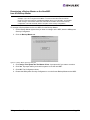
Procedure
To start the HBAnyware Security Configurator:
1. su to ‘root’.
2. Change to the application installation directory. Type:
./install ssc
3. Run the script:
/usr/sbin/hbanyware/ssc
Starting HBAnyware from the Command Line
Procedure
To launch the HBAnyware utility from the command line:
1. Type /usr/sbin/hbanyware/hbanyware. This starts the HBAnyware utility running in in-band
access. You can also start the HBAnyware utility running in out-of-band access by adding an
argument in the form “h=<host>”. The <host> argument may be either the IP address of the host
or its system name. The call will use a default IP port of 23333, but you can override this by
optionally appending a colon (:) and the IP port number.
Note: Remember that not all HBAs for a specific host may be running in-band.
Therefore, running that host out-of-band may display HBAs that do not
appear when the host is running in-band.
Examples of Modifications
•
./hbanyware h=138.239.82.2
The HBAnyware utility will show HBAs in the host with the IP address 138.239.82.2.
•
./hbanyware h=Util01
The HBAnyware utility will show HBAs in the host named Util01.
•
./hbanyware h=Util01
The HBAnyware utility will show HBAs in the host named Util01.
Run this modified command line to launch the HBAnyware utility for a single, remote host in
local mode.
Changing Management Mode
During installation you selected a management mode, however you can change it if you enabled that
option during installation.
The HBAnyware utility enables you to choose three types of host/HBA management:
•
Strictly Local Management - This setting only allows management of HBAs on this host.
Management of HBAs on this host from other hosts is not allowed.
•
Local Management Plus - This setting only allows management of HBAs on this host, but
management of HBAs on this host from another host is possible.
•
Full Management - This setting enables you to manage HBAs on this host and other hosts that
allow it.
HBAnyware User Manual
Page 3
To change management mode:
1. Run the following script:
/usr/sbin/hbanyware/set_operating_mode
2. Choose the management type you want.
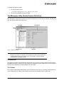
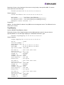
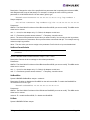
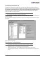
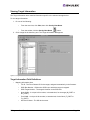
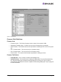
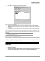
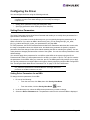
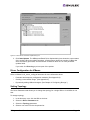
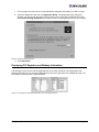
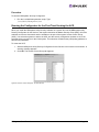
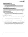
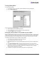
The HBAnyware Utility Window Element Definitions
The HBAnyware utility window contains five basic components: the menu bar, the toolbar, the discoverytree, the property tabs and the status bar.
Figure 1: HBAnyware window
Note: The element you select in the discovery-tree determines whether a menu item or
toolbar icon is active. For example, if you select the local host or other system host,
the Reset Adapter item on the Adapter menu is unavailable. The Reset Adapter
toolbar button is unavailable as well.
The Menu Bar
The menu bar contains command menus that enable you to perform a variety of tasks such as exiting
the HBAnyware utility, resetting host bus adapters and sorting items in the discovery-tree view. Many of
the menu bar commands are also available from the toolbar.
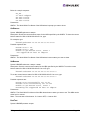
The Toolbar
The toolbar contains buttons that enable you to refresh the discovery-tree, reset the selected HBA and
sort the discovery-tree. Many of the toolbar functions are also available from the menu bar.
HBAnyware User Manual
Page 4
Figure 2: The Toolbar
The toolbar is visible by default. Use the Toolbar item in the View menu to hide the toolbar. If the item is
checked, the toolbar is visible.
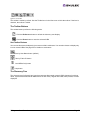
The Toolbar Buttons
The toolbar buttons perform the following tasks:
Click the Rediscover button to refresh the discovery-tree display.
Click the Reset button to reset the selected HBA.
Sort Toolbar Buttons
You can sort discovered adapters by host name or fabric addresses. You can also choose to display only
local or remote HBAs. See page 24 for details on sort buttons.
Sort by Host Name button (default)
Sort by Fabric ID button
Local HBAs Only button
Help button
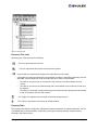
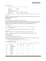
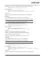
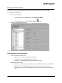
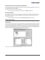
The Discovery-Tree
The discovery-tree (left pane) has icons that represent discovered network (SAN) elements (local host
name, system host names and all HBAs active on each host). Targets and LUNs, when present, are also
displayed.
HBAnyware User Manual
Page 5
Figure 3: Discovery-tree
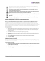
Discovery-Tree Icons
Discovery-tree icons represent the following:
This icon represents the local host.
This icon represents other hosts connected to the system.
A green HBA icon with black descriptive text represents an online HBA.
A gray HBA icon with red descriptive text represents an offline or otherwise temporarily inaccessible HBA. Several situations could cause the HBA to be offline or inaccessible:
•
The HBA on a local host is not connected to the network, but is still available for local
access.
•
The HBA on a local host is malfunctioning and is inaccessible to the local host as well as to
the network.
•
The HBA on a local host is busy performing a local download and is temporarily inaccessible
to the local host as well as to the network.
The Target icon represents connections to individual storage devices.
The LUN icon represents connections to individual LUNs.
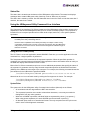
Property Tabs
The property tabs display configuration, statistical and status information for network elements. The set
of available tabs is context-sensitive, depending on the type of network element or HBA currently
selected in the discovery-tree.
HBAnyware User Manual
Page 6
Status Bar
The status bar is located near the bottom of the HBAnyware utility window. The status bar displays
messages about certain HBAnyware utility functions, such as “Discovery in process”.
The status bar is visible by default. Use the Status Bar item in the View menu to hide the status bar. If
checked, the status bar is visible.
Using the HBAnyware Utility Command-Line Interface
The Command Line Interface (CLI) Client component of the HBAnyware utility provides access to the
capabilities of the Remote Management library from a console command prompt. This component is
intended for use in scripted operations from within shell scripts, batch files, or the specific platform
equivalent.
Note: The HBAnyware utility can only discover and manage remote HBAs on hosts running
the HBAnyware utility’s elxhbamgr daemon.
Remote in-band capabilities of the HBAnyware utility are subject to fabric zoning
configuration. Remote hosts you want to discover and manage using the HBAnyware
utility must be in the same zone or discovered and managed out-of-band through an
Ethernet connection.
Using the CLI Client (Linux)
The CLI Client is a console application named HBACMD. Each time you run this application from the
command line, a single operation is performed.
The first parameter of this command is the requested operation. When the specified operation is
completed, the command prompt is displayed. Most operations retrieve information about an entity on
the SAN and display that information on the console.
Most of the CLI Client commands require one or more additional parameters that specify the nature of
the command. A parameter used by many hbacmd commands specifies the World Wide Port Name
(WWPN) of the HBA that is the target of the command. For example, the following command shows the
port attributes for the HBA with the specified WWPN:
/usr/sbin/hbanyware/hbacmd portattrib 10:00:00:00:c9:20:20:20
hbacmd can be run in out-of-band mode by making the first argument h=<host>. For example:
/usr/sbin/hbanyware/hbacmd h=cp-hp5670 listhbas
/usr/sbin/hbanyware/hbacmd h=138.239.91.121 listhbas
Syntax Rules
The syntax rules for the HBAnyware utility Command-Line Interface (hbacmd) are as follows:
•
All commands and their arguments are NOT case sensitive.
•
The requested operation must contain at least three characters, or as many as needed to
distinguish it from any other operation.
•
Whenever a WWPN is specified, individual fields are separated by colons (:) or spaces ( ).
When using space separators, the entire WWPN must be enclosed in quotes (").
•
All hbacmd inputs must be in hexadecimal format. The only exceptions are the cycle-counts
used in some of the diagnostic commands
HBAnyware User Manual
Page 7
Out-of-Band Access
Out-of-band (OOB) access enables you to access HBAs via their IP-address or by the name of the host
on which they reside. Since HBAs may exist on a host but not be a part of a FC network, they will not
appear during normal in-band discovery. Thus, OOB access enlarges the number of HBAs that can be
queried or modified.
Note: A local host cannot be accessed out-of-band.
OOB access via hbacmd uses an additional parameter on the command line. The parameter must be
the first parameter in the list, coming immediately after hbacmd. The remaining parameters are those
documented for each operation.
Note: You can also access an in-band HBA via its OOB address.
The format of the OOB parameter is:
h={<IPAddress> | <host-name>}
Some examples are:
h=128.239.91.88
h=cp-compaq8000
The following lists all HBAs running on the host with a specified IP address:
hbacmd h=128.239.91.88 listHBAs
If you don’t know the IP address, but you know the host name, type:
hbacmd h=cp-compaq8000 listHBAs
If the host is unreachable, the command will return an error.
The CLI Client Command Reference
Note: CLI Client commands are not case sensitive.
Note: The PersistentBinding, SetPersistentBinding, RemovePersistentBinding,
RemoveAllPersistentBinding, BindingCapabilities, BindingSupport and
SetBindingSupport commands are not supported for Linux.
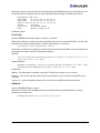
Version
Syntax: HBACMD Version
Description: Shows the current version of the HBAnyware CLI client application. To view the current
version, type:
hbacmd version
Sample response:
HBAnyware Command Line Interface: Version 3.2a3
Parameters: None.
ListHBAs
Syntax: HBACMD ListHBAs
HBAnyware User Manual
Page 8
Description: Shows a list of the discovered manageable Emulex HBAs and some of their attributes. The
list will contain one 6-attribute group for each discovered HBA. Example of an attribute group list:
Manageable HBA List
Port WWN:
10:00:00:00:c9:20:08:cc
Node WWN:
20:00:00:00:c9:20:08:cc
Fabric Name:10:00:00:60:69:90:0b:f6
Flags:
0000f900
Host Name: CP-EMULEX-DECPC
Mfg:
Emulex Corporation
Parameters: None.
SaveConfig
Syntax: HBACMD SaveConfig <wwpn> <filename> <ctrlword>
Description: Saves the contents of the driver parameter list to a file for the specified HBA. The ASCII file
lists parameter definitions, delimited by a comma. Each definition is of the form:
<parameter-name>=<parameter-value>
Save either the values of the global set or those specific to the referenced HBA. The file created by this
command stores itself in the Emulex Repository directory.
Example:
/usr/sbin/hbanyware/hbanyware/hbacmd saveconfig 10:00:00:00:c9:5e:f7:97
lpfc.linux.8x-8.1.10.9.dpv n
Sample response:
HBACMD_SaveConfig: Success writing driver parameters to file /usr/
sbin/hbanyware/RMRepository/lpfc.linux.8x-8.1.10.9.dpv
Parameters:
WWPN - The World Wide Port Name of the HBA. This HBA can be either local or remote.
filename - The file name that will contain the driver parameter list upon successful completion of this
command.
ctrlword - G = save the global parameter set. N = save the local (HBA-specific) parameter set.
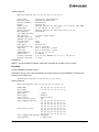
HBAAttrib
Syntax: HBACMD HBAAttrib <wwpn>
Description: Shows a list of all HBA attributes for the HBA with the specified WWPN. To view the
attributes for the HBA, type:
hbacmd hbaattrib 10:00:00:00:c9:20:08:cc
HBAnyware User Manual
Page 9
Sample response:
HBA Attributes for 10:00:00:00:c9:4a:c5:90
Host Name
:
Manufacturer
:
Serial Number :
Model
:
Model Desc
:
Node WWN
:
Node Symname
:
HW Version
:
Opt ROM Version:
FW Version
:
Vender Spec ID :
Number of Ports:
Driver Name
:
Device ID
:
HBA Type
:
Operational FW :
SLI1 FW
:
SLI2 FW
:
IEEE Address
:
Boot BIOS
:
Driver Version :
Kernel Version :
localhost.localdomain
Emulex Corporation
BG53059073
LP1150-F4
Emulex LP1150-F4 4Gb 1port FC: PCI-X2 SFF HBA
20 00 00 00 c9 4a c5 90
Emulex LP1150-F4 FV2.10A5 DV8.0.16.25
1036406d
2.10A5 (J2F2.10A5)
10DF
1
lpfc
F0D5
LP1150-F4
SLI-2 Overlay
SLI-1 Overlay 2.10a5
SLI-2 Overlay 2.10a5
00 00 c9 4a c5 90
Disabled
8.0.16.25; HBAAPI(I) v2.1.c, 02-02-06
1.11a5
Parameters:
WWPN - The World Wide Port Name of the HBA. This HBA can be either local or remote.
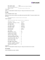
PortAttrib
Syntax: HBACMD PortAttrib <wwpn>
Description: Shows a list of all port attributes for the port with the specified WWPN. To view the port
attributes for the HBA, type:
hbacmd portattrib 10:00:00:00:c9:20:08:cc
Sample response:
Port Attributes for 10:00:00:00:c9:4a:c5:90
Node
Port
Port
Port
Port
Port
Port
Port
WWN
WWN
Symname
FCID
Type
State
Service Type
Supported FC4
:
:
:
:
:
:
:
:
20 00 00 00 c9 4a c5 90
10 00 00 00 c9 4a c5 90
11400
Fabric
Operational
12
00 00 01 20
00 00 00 00
00 00 00 00
00 00 00 00
Port Active FC4
: 00 00 01 00
00 00 00 00
00 00 00 00
00 00 00 00
Port Supported Speed: Unknown
Port Speed
: 2 GBit/sec.
HBAnyware User Manual
00
00
00
00
00
00
00
00
00
00
00
00
00
00
00
00
00
00
00
00
00
00
00
00
01
00
00
00
01
00
00
00
Page 10
Max Frame Size
: 2048
OS Device Name
: /sys/class/scsi_host/host10
Num Discovered Ports: 3
Fabric Name
: 10 00 00 60 69 50 15 25
Parameters:
WWPN - The World Wide Port Name of the port. This port can be either local or remote.
PortStat
Syntax: HBACMD PortStat <wwpn>
Description: Shows all port statistics for the HBA with the specified WWPN. To view port statistics for the
HBA, type:
hbacmd portstat 10:00:00:00:c9:20:08:cc
Sample response:
Port Statistics for 10:00:00:00:c9:20:08:cc
Exchange Count
:
Responder Exchange Count:
TX Seq Count
:
RX Seq Count
:
TX Frame Count
:
RX Frame Count
:
TX Word Count
:
RX Word Count
:
TX KB Count
:
RX KB Count
:
LIP Count
:
NOS Count
:
Error Frame Count
:
Dumped Frame Count
:
Link Failure Count
:
Loss of Sync Count
:
Loss of Signal Count
:
Prim Seq Prot Err Count :
Invalid TX Word Count
:
nvalid RX Frame CRC Cnt :
Link Transition Count
:
Active RPI Count
:
Active XRI Count
:
Rx Port Busy Count
:
Rx Fabric Busy Count
:
Primary Sequence Timeout:
Elastic Buffer Overrun :
Arbitration Timout
:
1496534
37505
1588007
1561255
1588695
1561892
19821312
66368000
77427
259250
1
n/a
0
n/a
0
9
0
0
0
0
0
0
0
0
0
0
0
0
Parameters:
WWPN - The World Wide Port Name of the port. This port can be either local or remote.
ServerAttrib
Syntax: HBACMD ServerAttrib <WWPN>
HBAnyware User Manual
Page 11
Description: Shows a list of attributes of the server running locally to the specified HBA. To view the
server attributes for the HBA, type:
hbacmd serverattrib 10:00:00:00:c9:20:08:cc
Sample response:
Server Attributes for 10:00:00:00:c9:4a:c5:90
Host Name
: localhost.localdomain
FW Resource Path: /usr/sbin/hbanyware/RMRepository/
DR Resource Path: /usr/sbin/hbanyware/RMRepository/
HBAnyware Server Version: 3.0
Parameters:
WWPN - The World Wide Port Name of any HBA local to the designated server. The HBA itself can be
either local or remote.
TargetMapping
Syntax: HBACMD TargetMapping <wwpn>
Description: Shows a list of mapped targets and the LUNs attached to each for the port with the
specified WWPN. To view the target mapping for 10:00:00:00:c9:20:08:0c, type:
hbacmd targetmapping 10:00:00:00:c9:20:08:0c
Sample response:
Target Mapping for 10:00:00:00:c9:4a:c5:90
FCP ID
:
SCSI Bus Number:
SCSI Target Num:
Node WWN
:
Port WWN
:
Tgt Device Name:
115E2
0
0
50:00:60:E8:02:78:6E:03
50:00:60:E8:02:78:6E:03
/dev/sdb
FCP LUN 00
:
SCSI OS Lun
:
Lun Device Name:
Vendor ID
:
Product ID
:
Product Version:
SCSI Capacity :
Block Size
:
0000 0000 0000 0000
0
/dev/sdb
HITACHI
OPEN-3
0118
2347 MB
512 Bytes
FCP LUN 01
:
SCSI OS Lun
:
Lun Device Name:
Vendor ID
:
Product ID
:
Product Version:
SCSI Capacity :
Block Size
:
0001 0000 0000 0000
1
/dev/sdb
HITACHI
OPEN-3
0118
2347 MB
512 Bytes
FCP LUN 02
:
SCSI OS Lun
:
Lun Device Name:
Vendor ID
:
Product ID
:
0002 0000 0000 0000
2
/dev/sdb
HITACHI
OPEN-3
HBAnyware User Manual
Page 12
Product Version: 0118
SCSI Capacity : 2347 MB
Block Size
: 512 Bytes
Parameters:
WWPN - The World Wide Port Name of the port. This port can be either local or remote.
Reset
Syntax: HBACMD Reset <wwpn>
Description: Resets the HBA with the specified WWPN. Resetting an HBA may require several seconds
to complete, especially for remote devices. This command will return for additional input only after the
reset has finished. To reset an HBA whose WWPN is 10:00:00:00:c9:e:51:2e, type:
hbacmd reset 10:00:00:00:c9:2e:51:2e
Sample response:
Reset HBA 10:00:00:00:c9:2e:51:2e
Parameters:
WWPN - The World Wide Port Name of the port. This port can be either local or remote.
Download
Syntax: HBACMD Download <wwpn> <filename>
Description: Loads the specified firmware image to the HBA with the specified WWPN. To load the
firmware image located in hdc190a4.dwc to an HBA with WWPN 10:00:00:00:c9:2e:51:2e, type:
hbacmd download 10:00:00:00:c9:2e:51:2e hdc190a4.dwc
Sample response for a successful download:
Downloading hdc190a4.dwc to hba 10:00:00:00:c9:2e:51:2e
Download Complete.
Parameters:
WWPN - The World Wide Port Name of the HBA that is the target of the firmware download. This HBA
can be either local or remote.
FileName - The file name of the firmware image you want to load. This can be any file accessible to the
CLI client application.
AllNodeInfo
Syntax: HBACMD AllNodeInfo <wwpn>
Description: Shows target node information for each target accessible from the specified HBA. To view
the target node data for 10:00:00:00:c9:20:0d:36, type:
Hbacmd allnodeinfo 10:00:00:00:c9:20:0d:36
HBAnyware User Manual
Page 13
Sample response:
All Node Info for 10:00:00:00:c9:4a:c5:90
Node Type
:
FCP ID
:
SCSI Bus Number:
SCSI Target Num:
Node WWN
:
Port WWN
:
OS Device Name :
EXIST
115E2
0
0
50:00:60:E8:02:78:6E:03
50:00:60:E8:02:78:6E:03
/sys/class/scsi_host/host10/device/target10:0:0
Parameters:
WWPN - The World Wide Port Name of the HBA whose target node information you want to query. This
HBA can be either local or remote.
DriverConfig
Syntax: HBACMD driverconfig <wwpn> <filename><ctrlword>
Description: Sets all driver parameters for the HBA specified by WWPN to the driver parameter values
contained in the driver parameter file. These files can be easily generated via the HBAnyware Driver
Parameter tab. Driver types must match between .dpv file type and host platform HBA.
For example, type:
hbacmd driverconfig 10:00:00:00:c9:2e:51:2e elxconfig G
Below is a sample response:
hbacmd: Success setting driver configuration parameters to values in .dpv file.
Parameters:
WWPN - The World Wide Port Name of the HBA on which to set driver parameters.
ctrlword - G = save the global parameter set. N = make change neither permanent nor global.
GetDriverParams
Syntax: HBACMD GetDriverParams <wwpn>
Description: Shows the name and values of each driver parameter for the selected HBA. To view the
driver parameters for HBA 10:00:00:00:c9:2e:51:2e, type:
hbacmd getdriverparams 10:00:00:00:c9:2e:51:2e
Sample (abbreviated) response:
Driver Params for 10:00:00:00:c9:4a:c5:90. Values in HEX format.
DX
string
Low
High
Def
Cur
Exp
Dyn
00
log-verbose
0
ffff
0
20
1
1
01
lun-queue-depth
1
80
1e
1e
1
4
02
scan-down
0
1
1
1
1
4
03
nodev-tmo
0
ff
1e
3c
1
1
04
topology
0
6
0
0
1
4
05
link-speed
0
4
0
0
1
4
06
fcp-class
2
3
3
3
1
4
07
use-adisc
0
1
0
1
1
1
08
ack0
0
1
0
0
1
4
HBAnyware User Manual
Page 14
09
fcp-bind-method
1
4
2
2
1
4
0a
cr-delay
0
3f
0
0
1
4
0b
cr-count
1
ff
1
1
1
4
0c
fdmi-on
0
2
0
0
1
4
0d
discovery-threads
1
40
20
20
1
4
0e
max-luns
1
8000
100
100
1
4
Parameters:
WWPN - The World Wide Port Name of the HBA whose driver parameters you want to view. This HBA
can be either local or remote.
GetParamsGlobal
Syntax: HBACMD GetParamsGlobal <wwpn>
Description: Shows the name and the global value of each driver parameter for the selected HBA. To
view the global driver parameters for HBA 10:00:00:00:c9:2e:51:2e, type:
hbacmd getparamsglobal 10:00:00:00:c9:2e:51:2e
Sample (abbreviated) response:
Driver Params (Global) for 10:00:00:00:c9:2e:51:2e. Values in HEX.
DX
string
Low
High
glbl
Cur
Exp
Dyn
00
log-verbose
0
ffff
0
40
1
1
01
lun-queue-depth
1
80
1e
1e
1
4
02
scan-down
0
1
1
1
1
4
03
nodev-tmo
0
ff
1e
1e
1
1
04
topology
0
6
0
0
1
4
05
link-speed
0
4
0
0
1
4
06
fcp-class
2
3
3
3
1
4
07
use-adisc
0
1
0
0
1
1
08
ack0
0
1
0
0
1
4
09
cr-delay
0
3f
0
0
1
4
0a
cr-count
1
ff
1
1
1
4
0b
fdmi-on
0
2
0
0
1
4
0c
discovery-threads
1
40
20
20
1
4
0d
max-luns
1
8000
100
100
1
4
Parameters:
WWPN - The World Wide Port Name of the HBA whose driver parameters you want to view. This HBA
can be either local or remote.
SetDriverParam
Note: This command may only be used with the log-verbose, use-adisc and nodev-tmo
parameters.
Syntax: HBACMD SetDriverParam <wwpn> <cw1> <cw2><param> <value>
HBAnyware User Manual
Page 15
Description: Changes the value of the specified driver parameter that is operating the referenced HBA,
and designates the scope of that change. For example, to change the value of the log-verbose
parameter for 10:00:00:00:c9:2e:51:2e and make it global, type:
hbacmd SetDriverParam 10:00:00:00:c9:2e:51:2e g log-verbose 3
Sample response:
Set Driver Parameter log-verbose=3(g) for 10:00:00:00:c9:2e:51:2e
Parameters:
WWPN - The World Wide Port Name of the HBA whose Boot BIOS you want to modify. This HBA can be
either local or remote.
cw1 - L = Local, for this adapter only. G = Global, all adapters on this host.
cw2 - P = Permanent, persists across reboots. T = Temporary, lost after reboot.
param - The name of the parameter whose value you want to modify. You can only use the log-verbose,
use-adisc and nodev-tmo parameters. Do not preceed these commands with lpfc-. For example use logverbose not lpfc-log-verbose.
Value - The new value you want to assign to the parameter. Prefix with 0x to input as hexadecimal.
SetDriverParamDefaults
Note: This command may only be used with the log-verbose, use-adisc and nodev-tmo
parameters.
Syntax: HBACMD SetDriverParamDefaults <wwpn> <cw1> <cw2>
Description: Returns the driver settings to their default parameters.
Parameters:
WWPN - The World Wide Port Name of the HBA whose Boot BIOS you want to modify. This HBA can be
either local or remote.
cw1 - L = Local, for this adapter only. G = Global, all adapters on this host.
cw2 - P = Permanent, persists across reboots. T = Temporary, lost after reboot.
SetBootBios
Syntax: HBACMD SetBootBios <wwpn> <ctrlword>
Description: Enables or disables the BootBIOS on the referenced HBA. To enable the BootBIOS for
10:00:00:00:c9:2e:51:2e, type:
hbacmd setbootbios 10:00:00:00:c9:2e:51:2e E
Parameters:
WWPN - The World Wide Port Name of the HBA whose BootBIOS you want to modify. This HBA can be
either local or remote.
ctrlword - E = enable the Boot BIOS, D = disable the BootBIOS.
PciData
Syntax: HBACMD PciData <wwpn>
HBAnyware User Manual
Page 16
Description: Shows PCI configuration data for the HBA specified by the WWPN. To show PCI
configuration data for HBA 10:00:00:00:c9:2e:51:2e, type:
hbacmd pcidata 10:00:00:00:c9:2e:51:2e
Sample response:
Vendor ID:
Command:
Revision ID:
Subclass:
Cache Line Size:
Header Type:
Base Address 0:
0x00000000
Base Address 2:
0x00000000
Base Address 4:
0x00000000
CIS:
SubSystem ID:
Interrupt Line:
Minimum Grant:
Capabilities Ptr:
0x10DF
0x0157
0x01
0x04
0x20
0x00
0xE0001004
Device ID:
Status:
Prog If:
Base Class:
Latency Timer:
Built In Self Test:
Base Address 1:
0xE0000004
Base Address 3:
0x0000C001
Base Address 5:
0x00000000
0xF0D5
0xFF
0xFF
0x5C
SubVendor ID:
ROM Base Address:
Interrupt Pin:
Maximum Latency:
0xF0D5
0x0230
0x00
0x0C
0xF8
0x00
0x10DF
0x00000000
0x01
0x00
Parameters:
WWPN - The World Wide Port Name of the HBA whose PCI configuration data you want to show.
Wakeup
Syntax: HBACMD wakeup <wwpn>
Description: Shows wakeup parameter data for the HBA specified by the WWPN. To show wakeup
parameter data for HBA 10:00:00:00:c9:2e:51:2e, type:
hbacmd wakeup 10:00:00:00:c9:2e:51:2e
Sample response:
Wakeup Parameters:
Initial Load:
0x02C03992
Flags:
0x00000000
0x00103411
Boot BIOS
0x03433290
SLI-1:
0x06433992
0x00103411
SLI-2:
0x07433992
0x00103411
Has Expansion ROM
0
0x00101303
Parameters:
WWPN - The World Wide Port Name of the HBA whose wakeup parameter data you want to show.
LoopMap
Syntax: HBACMD loopmap <wwpn>
Description: Shows the arbitrated loop map data for the HBA specified by the WWPN. To show the
arbitrated loop map data for HBA 10:00:00:00:c9:2e:51:2e, type:
hbacmd loopmap 10:00:00:00:c9:2e:51:2e
HBAnyware User Manual
Page 17
Below is a sample response:
AL_PA:
01 Local Adapter
E8 SCSI Device
E4 SCSI Device
CA SCSI Device
Parameters:
WWPN - The World Wide Port Name of the HBA whose loopmap you want to show.
GetBeacon
Syntax: HBACMD getbeacon <wwpn>
Description: Shows the current beacon status for the HBA specified by the WWPN. To show the current
beacon status for HBA 10:00:00:00:c9:2e:51:2e, type:
For example, type:
hbacmd getbeacon 10:00:00:00:c9:2e:51:2e
Possible responses are:
Beacon State = On
Beacon State = Off
Unable to get Beacon state, error 1
not supported on host or adapter
Parameters:
WWPN - The World Wide Port Name of the HBA whose beacon status you want to show.
SetBeacon
Syntax: HBACMD setbeacon <wwpn> <state>
Description: Sets the current beacon status for the HBA specified by the WWPN. To set the current
beacon status for HBA 10:00:00:00:c9:2e:51:2e to off, type:
hbacmd setbeacon 10:00:00:00:c9:2e:51:2e 0
To set the current beacon status for HBA 10:00:00:00:c9:2e:51:2e to on, type:
hbacmd setbeacon 10:00:00:00:c9:2e:51:2e 1
Possible responses are:
Beacon State successfully set to On
Beacons State successfully set to Off
Unable to get Beacon state, error 1
Beaconing not supported on host or adapter
Parameters:
WWPN - The World Wide Port Name of the HBA whose beacon status you want to set. This HBA can be
either local or remote.
State - The new state of the beacon: 0 = beacon OFF, 1= beacon ON
PostTest
Syntax: HBACMD posttest <wwpn>
HBAnyware User Manual
Page 18
Description: Runs the POST test on the HBA specified by the WWPN. Support for remote HBA is out-ofband (Ethernet) only. To run the POST test for HBA 10:00:00:00:c9:2e:51:2e, type:
hbacmd posttest 10:00:00:00:c9:2e:51:2e
Sample response:
Running POST, polling for results.....
Power On Self Test Succeeded;time to execute = 8928 ms
Parameters:
WWPN - The World Wide Port Name of the HBA on which to run the POST test.
EchoTest
Syntax: HBACMD echotest <wwpn1> <wwpn2> <count> <StopOnError>
Description: Runs the echo test on the HBAs specified by the WWPN1 and WWPN2.
Note: Support for remote HBA is out-of-band (Ethernet) only. The EchoTest command will
fail if the target WWPN does not support the ECHO ELS command.
To run the echo test for HBA 10:00:00:00:c9:2e:51:2e, type:
hbacmd echotest 10:00:00:00:c9:2e:51:2e
10:00:00:00:c9:2e:51:45 10 1
Sample response:
Echo test: polling for results......
Echo test succeeded; time to execute = 53 ms.
Parameters:
WWPN1 - The World Wide Port Name of the originating HBA.
WWPN2 - The World Wide Port Name of the destination (echoing) HBA.
Count - The number of times to run the test.
StopOnError - Should the test be halted on Error? 0 = no halt, 1 = halt
Loopback
Syntax: HBACMD loopback <wwpn> <type> <count> <StopOnError>
Description: Runs the loop test on the HBA specified by the WWPN.
Note: Only external Loopback tests must be run out-of-band.
To run the loop test for HBA 10:00:00:00:c9:2e:51:2e, type:
hbacmd loopback 10:00:00:00:c9:2e:51:2e 1 10 0
Sample response:
Running Loopback: polling for results......
Loopback Test Failed; xmit errors = 3; rcv errors = 2; time to
execute = 1015 ms.
Parameters:
WWPN - The World Wide Port Name of the HBA on which to run the loopback test(s).
HBAnyware User Manual
Page 19
Type - Type of loopback test where: 0 = PCI LoopBack Test, 1 = Internal LoopBack Test, 2 = External
LoopBack Test
Count - The number of times to run the test (Range = 1,...10000).
StopOnError - Should the test be halted on Error? 0 = no halt, 1 = halt
Dump
Syntax: HBACMD dump <wwpn>
Description: Runs the dump diagnostic retrieval command on the HBA specified by the WWPN. This
command is supported for local HBAs only. The file by default is located in:
/usr/sbin/hbanyware/Dump
To run the dump diagnostic retrieval command for HBA 10:00:00:00:c9:2e:51:2e, type:
hbacmd dump 10:00:00:00:c9:2e:51:2e
Sample response (Abbreviated list):
Revision Information: OS Version
Linux, 2.6.16.20-0.12-smp
Revision Information: Driver Version
Driver Type: Linux lpfc
Driver Name: lpfc
Driver Version: 8.1.6.2; HBAAPI(I) v2.1.c, 02-02-06
Revision Information: HBAnyware Version
HBAnyware Version: 3.2a3
DFC Lib Version:
2.14.0
HBA Information: Adapter Model
Model: LPe11002-M4
Description: Emulex LPe11002-M4 4Gb 2port FC: PCIe SFF HBA
HBA Information: Adapter WWN
Port WWN: 10:00:00:00:c9:4e:2b:28
Node WWN: 20:00:00:00:c9:4e:2b:28
HBA Information: Adapter Serial Number
Adapter Serial Number: VM54139218
HBA Information: Firmware Version
Firmware Version: 2.50A6 (Z2F2.50A6)
Operational FW Version: SLI-2 Overlay
SLI-1 FW Version: SLI-1 Overlay 2.50a6
SLI-2 FW Version: SLI-2 Overlay 2.50a6
Kernel FW Version: 1.12a6
HBA Information: Boot Bios Version
Boot Bios State: 0
Boot Bios Version: Boot Bios Firmware 5.01a7
Parameters:
WWPN - The World Wide Port Name of the HBA on which to you want to run the dump.
HBAnyware User Manual
Page 20
DeleteDumpFiles
Syntax: HBACMD deletedumpfiles <wwpn>
Description: Deletes all dump files associated with the HBA specified by the WWPN. To delete all dump
files for HBA 10:00:00:00:c9:2e:51:2e, type:
hbacmd deletedumpfiles 10:00:00:00:c9:2e:51:2e
Sample response:
HBACMD: Dump file deletion complete.
Parameters:
WWPN - The World Wide Port Name of the HBA whose dump files you want to delete.
HBAnyware User Manual
Page 21
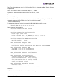
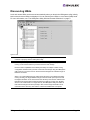
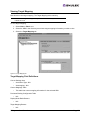
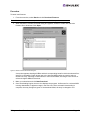
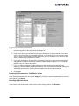
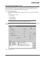
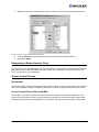
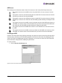
Discovering HBAs
Local and remote HBAs are discovered automatically when you launch the HBAnyware utility. Initially,
both local and remote HBAs are displayed. You can also discover HBAs on out-of-band (OOB) hosts.
For more information, see “The HBAnyware Utility Window Element Definitions” on page 4.
Figure 4: Discovery information
Note: Emulex recommends setting the monitor display resolution to 1024x768 as a
minimum to properly view the HBAnyware utility.
Note: The HBAnyware utility must be installed and the elxhbamgr process(es) must be
running on all remote hosts that you want to discover and manage.
Remote in-band capabilities of the HBAnyware utility are subject to fabric zoning
configuration. Remote hosts you want to discover and manage using the HBAnyware
utility must be in the same zone or discovered and managed out-of-band through an
Ethernet connection.
When n an in-band HBA becomes undiscovered (as seen by the HBAnyware utility
running remotely) the target WWPN changes color from black (normal) to blue and
the target information is not removed from the discovery-tree until the undiscovered
HBA timer has expired (See Configuring Discovery Settings on page 23). Similarly,
when an out-of-band host is no longer seen by the HBAnyware utility, the HBAs on
that host will change from black (normal) to blue, and the target information is not
removed from the discovery-tree until the undiscovered HBA timer has expired.
HBAnyware User Manual
Page 22
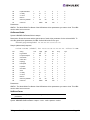
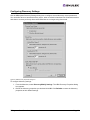
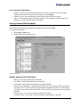
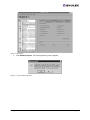
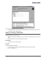
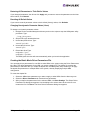
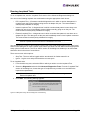
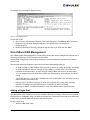
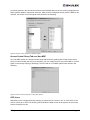
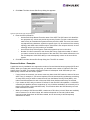
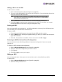
Configuring Discovery Settings
Use the HBAnyware Discovery Settings dialog box to configure several discovery server parameters.
You can define when to start the discovery server, when to refresh in-band and out-of-band discoveries
and when to remove previously discovered HBAs that are no longer being discovered.
Figure 5: HBA Discovery Properties dialog box
To configure discovery settings:
1. From the Menu bar, select Discovery/Modify Settings. The HBA Discovery Properties dialog
box appears.
2. Define the discovery properties you wish and click OK. Click Defaults to return the discovery
properties to their default settings.
HBAnyware User Manual
Page 23
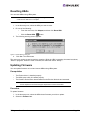
Sorting HBA Information
Sort discovered HBAs by host name, fabric name, HBA name, target name and LUN number. You can also
choose to view local HBAs or remote HBAs. By default, both local and remote HBAs are sorted by host
name/fabric name.
To sort HBAs:
1. Switch between host name or fabric ID in one of two ways:
•
From the menu bar: click View, then click Sort by Host Name or Sort by Fabric ID. The
current adapter display mode is checked.
•
From the toolbar, click one of the following buttons:
Sort HBAs by Host Name (default).
Sort HBAs by Fabric ID.
2. The HBAnyware utility sorts in ascending order. The sort recognizes letters, numbers, spaces
and punctuation marks.
Sort by Host Name
•
Initially sorts by host name. You cannot change host names using the HBAnyware utility; names
must be changed locally on that system.
•
Within each host system, sorts by HBA model.
•
If multiple HBAs have the same model number, sorts models by World Wide Node Name
(WWNN).
•
If targets are present, sorts by World Wide Port Name (WWPN). Multiple HBAs may refer to the
same target.
•
If LUNs are present, sorts by LUN number.
Sort by Fabric Address
•
Initially sorts by fabric ID.
•
Within each fabric ID, sorts by HBA model.
•
If multiple HBAs have the same model number, sorts models by WWNN.
•
If targets are present, sorts by WWPN. Multiple HBAs may refer to the same target.
•
If LUNs are present, sorts by LUN number.
•
If the fabric ID is all zeros, no fabric is attached.
Sorting Local HBAs Only
Displays local HBA's only. Works in conjunction with the Sort by Host Name and Sort by Fabric ID buttons.
To display local HBAs only, do one of the following:
•
From the menu bar: click View, then click Local HBAs Only. The current adapter display mode
is checked.
•
From the toolbar, click the Local HBAs Only
HBAnyware User Manual
button.
Page 24
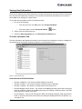
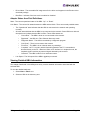
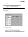
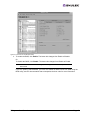
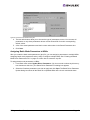
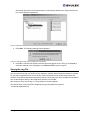
Viewing HBA Information
Viewing Discovery Information
The Discovery Information area contains a general summary of the discovered elements. The Host or
Fabric icon, depending upon which view you select, is the root of the discovery-tree, but it does not
represent a specific network element. Expanding it will reveal all hosts, LUNs, targets and HBAs that are
visible on the storage area network (SAN).
To view the discovery information:
1. Click the Host or Fabric icon at the root of the discovery-tree. Discovered SAN elements appear
in the discovery-tree. Select an element from the discovery-tree to learn more about it.
Figure 6: Discovery information
Discovery Information Field Definitions
•
Number of Hosts - The total number of discovered host computers. This includes servers,
workstations, personal computers, multiprocessors and clustered computer complexes.
•
Number of Fabrics - The total number of discovered fabrics.
•
Number of Adapters -The total number of discovered HBAs.
•
Number of Targets - The total number of unique discovered targets on the SAN. In the
discovery-tree, the same target can appear under more than one HBA.
HBAnyware User Manual
Page 25
Viewing Host Information
There are two tabs that show host information: the Host Information tab and the host Driver Parameters
tab. The Host Information tab is read-only. The host Driver Parameters tab enables you to view and
define HBA driver settings for a specific host.
To view the Host Information and Driver Parameters tabs:
1. Do one of the following:
•
From the menu bar, click View, then click Sort by Host Name.
•
From the toolbar, click the Sort by Host Name
button.
2. Select a host in the discovery-tree.
3. Select the Host Information tab or the Host Driver Parameters tab.
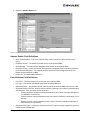
The Host Information Tab
The Host Information tab displays information for the selected host including the number of adapters in
the selected host, the number of fabrics to which it is connected and so on.
Figure 7: Host Information tab
Host Information Field Definitions
•
Number of Adapters - The number of HBAs installed in the host.
•
Number of Fabrics - The number of fabrics to which this host is attached.
•
Number of Targets - The number of storage devices seen by the host.
•
Remote Manager Server Version - The version of the HBAnyware utility server that is running on
the host. If different versions of the HBAnyware utility are installed on different hosts in the SAN,
those differences appear in this field.
•
Host IP Address - If the host is discovered in-band, the dialog box displays "Host discovered inband”. If the host is discovered out-of-band, the dialog box displays the host's IP address, e.g.,
138.239.82.131.
HBAnyware User Manual
Page 26
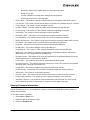
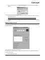
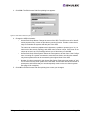
The Host Driver Parameters Tab
The Host Driver Parameters tab enables you to view and edit the HBA driver settings contained in a
specific host. The host driver parameters are global values and apply to all HBAs in that host unless they
are overridden by parameters assigned to a specific HBA using the HBA Driver Parameters tab. For
each parameter, the tab shows the current value, the range of acceptable values, the default value, and
whether the parameter is dynamic (a dynamic parameter allows the change to take effect without
resetting the HBA or rebooting the system).
Note: For the Linux 2.6 kernel, most driver parameters are set globally. You can set the
lpfc_log_verbose, lpfc_nodev_tmo and lpfc_use_adisc locally.
For more information on changing the parameters for a single HBA, see “Setting Driver Parameters for
an HBA” on page 44.
For more information changing the parameters for the host, see “Setting Driver Parameters for a Host”
on page 46.
Figure 8: Host Driver Parameters tab
Driver Parameter Tab Field Definitions
Note: If there is more than one driver type installed, the Installed Driver Types menu shows
a list of all driver types and driver versions that are installed on the HBAs in the host.
•
Installed Driver Type - The current driver and version installed.
•
Adapter Parameter table - A list of HBA driver parameters and their current values.
•
Parameter-specific information - The details about the parameter appears on the right side of
the tab.
HBAnyware User Manual
Page 27
Driver Parameter Tab Buttons
•
Restore - Click to save and restore parameters to this last saved value, if you have made
changes to parameters and have not saved them by clicking Apply.
•
Defaults - Click to reset all parameter values to their default (out-of-box) values.
•
Apply - Click to apply any driver parameter changes. If you changed a parameter that is not
dynamic, you must unload the driver and reload it.
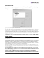
Viewing General HBA Attributes
The General tab contains general attributes associated with the selected HBA.
To view general attributes:
1. Select Host or Fabric sort.
2. Select an HBA in the discovery-tree.
Figure 9: General tab
Adapter Summary Field Definitions
•
Model - The complete model name of the HBA.
•
Port WWN - The Port World Wide Name of the HBA.
•
Node WWN - the Node World Wide Name of the selected HBA.
•
Fabric Name or Host Name - The Fabric Name field shows if you selected, “Sort by Host Name”.
The fabric name is a 64-bit worldwide unique identifier assigned to the fabric. The Host Name
field shows if you selected “Sort by Fabric ID”. The host name is the name of the host containing
the HBA.
•
Driver Version - The version of the driver installed for the HBA.
•
Firmware Version - The version of Emulex firmware currently active on the HBA.
HBAnyware User Manual
Page 28
•
Driver Name - The executable file image name for the driver as it appears in the Emulex driver
download package.
•
Boot Bios - Indicates if the boot code is enabled or disabled.
Adapter Status Area Field Definitions
State - The current operational state of the HBA: “Up” or “Down”.
Link Status - The current link status between the HBA and the fabric. There are several possible states:
•
The “Operational” state indicates that the HBA is connected to the network and operating
normally.
•
All other states indicate that the HBA is not connected to the network. Green HBA icons with red
descriptive text indicate that the HBA is offline. These offline states are:
•
•
“User offline” - The HBA is down or not connected to the network.
•
“Bypassed” - the HBA is in Fibre Channel discovery mode.
•
“Diagnostic Mode” - The HBA is controlled by a diagnostic program.
•
“Link Down” - There is no access to the network.
•
“Port Error” - The HBA is in an unknown state; try resetting it.
•
“Loopback” -an FC-1 mode in which information passed to the FC-1 transmitter is
shunted directly to the FC-1 Receiver. When a FC interface is in loopback mode, the
loopback signal overrides any external signal detected by the receiver.
•
“Unknown” -The HBA is offline for an unknown reason.
Link Speed - The link speed of the HBA in gigabits per second.
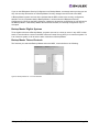
Viewing Detailed HBA Information
The Adapter Details tab in the HBAnyware utility contains detailed information associated with the
selected HBA.
To view the detailed attributes:
1. Select Host or Fabric sort.
2. Select an HBA in the discovery-tree.
HBAnyware User Manual
Page 29
3. Select the Adapter Details tab.
Figure 10: Adapter Details tab
Adapter Details Field Definitions
•
Node Symbolic Name - The Fibre Channel name used to register the driver with the name
server.
•
Hardware Version - The JEDEC ID board version of the selected HBA.
•
Serial Number - The manufacturer assigned serial number of the selected HBA.
•
Discovered Ports - Counts the number of mapped and unmapped ports found during discovery
by the Emulex HBA driver. The mapped ports are targets and the unmapped ports are non
targets such as switches or HBAs.
•
Device ID - The HBA's default device ID.
Port Attributes Field Definitions
•
Port FC ID - The Fibre Channel ID for the port of the selected HBA.
•
Port Type - The current operational mode of the selected HBA’s port.
•
OS Device Name - The platform-specific name by which the selected HBA is known to the OS.
•
Supported Class of Service - A frame delivery scheme exhibiting a set of delivery characteristics
and attributes. There are three classes of service.
•
•
Class-1 provides a dedicated connection between a pair of ports confirmed with delivery
or notification of nondelivery.
•
Class-2 provides a frame switched service with confirmed delivery or notification of nondelivery.
•
Class-3 provides a frame switched service similar to Class-2 but without notification of
frame delivery or non-delivery.
Supported FC4 Types - a 256-bit (8-word) map of the FC-4 protocol types supported by the port
containing the selected HBA.
HBAnyware User Manual
Page 30
Loop Map Table Definitions
•
The loop map shows the different ports present in the loop, and is present only if the port (HBA)
is operating in loop mode. The simplest example would be to connect a JBOD directly to an
HBA. When this is done, the port type will be a private loop, and the loop map will have an entry
for the HBA, and one entry for each of the disks in the JBOD.
Viewing Fabric Information
The Discovery Information area contains information about the selected fabric.
To view the fabric information:
1. Do one of the following:
•
From the menu bar, click View, then click Sort by Fabric ID.
•
From the toolbar, click the Sort by Fabric ID
button.
2. Click on a fabric address in the discovery-tree. The Discovery Information tab shows information
about the selected fabric.
Figure 11: Discovery information
Discovery Information Field Definitions
•
Number of Hosts - The number of hosts discovered or seen by this host on the selected fabric.
•
Number of Fabrics - The number fabrics identified during discovery.
•
Number of Adapters - The number of HBAs discovered by this host on the selected fabric.
•
Number of Targets - The number of storage devices seen by this host on the selected fabric.
HBAnyware User Manual
Page 31
Viewing Target Information
The Target Information area contains information specific to the selected storage device.
To view target information:
1. Do one of the following:
•
From the menu bar, click View, then click Sort by Host Name.
•
From the toolbar, click the Sort by Host Name
button.
2. Click a target in the discovery-tree. The Target Information tab appears.
Figure 12: Target Information tab
Target Information Field Definitions
•
Mapping Information Area
•
FC ID - The Fibre Channel ID for the target; assigned automatically in the firmware.
•
SCSI Bus Number - Defines the SCSI bus to which the target is mapped.
•
SCSI Target Number - The target's identifier on the SCSI bus.
•
Node WWN - A unique 64-bit number, in hexadecimal, for the target (N_PORT or
NL_PORT).
•
Port WWN - A unique 64-bit number, in hexadecimal, for the fabric (F_PORT or
FL_PORT).
•
OS Device Name - The OS device name.
HBAnyware User Manual
Page 32
Viewing LUN Information
The LUN Information area contains information about the selected logical unit number (LUN).
To view the LUN information:
1. Do one of the following:
•
From the menu bar, click View, then click Sort by Host Name.
•
From the toolbar, click the Sort by Host Name
button.
2. Select a LUN in the discovery-tree.
Figure 13: LUN Information tab
LUN Information Field Definitions
•
•
Vendor Product Information Area
•
Vendor ID - The name of the vendor of the LUN.
•
Product ID - The vendor-specific ID for the LUN.
•
Revision - The vendor-specific revision number for the LUN.
Mapping Information Area
•
FCP LUN - The Fibre Channel identifier used by the HBA to map to the SCSI OS LUN.
•
SCSI OS LUN - The SCSI identifier used by the OS to map to the specific LUN.
•
OS Device Name - The name assigned by the operating system (OS) to the selected
LUN.
HBAnyware User Manual
Page 33
•
LUN Capacity
Note: LUN capacity information is only provided when the LUN is a mass-storage (disk)
device. Other devices like tapes and scanners, etc. do not display capacity.
•
Capacity - The capacity of the LUN, in megabytes.
•
Block Length - The length of a logical unit block in bytes.
Viewing Port Statistics
The Statistics tab provides cumulative totals for various error events and statistics on the port. Some
statistics are cleared when the HBA is reset.
To view port statistics:
1. Select Host or Fabric sort.
2. Select an HBA in the discovery-tree.
3. Click the Statistics tab.
Figure 14: Statistics tab
Port Statistics Field Definitions
•
Tx Frames - Fibre Channel frames transmitted by this HBA port.
•
Tx Words - Fibre Channel words transmitted by this HBA port.
•
Tx KB Count - Fibre Channel kilobytes transmitted by this HBA port.
•
Tx Sequences - Fibre Channel sequences transmitted by this HBA port.
•
LIP count - The number of loop initialization primitive (LIP) events that have occurred for the
port. This field is not supported if the topology is not arbitrated loop. Loop initialization consists
of the following:
•
Temporarily suspend loop operations.
HBAnyware User Manual
Page 34
•
Determine whether loop capable ports are connected to the loop.
•
Assign AL_PA IDs.
•
Provide notification of configuration changes and loop failures.
•
Place loop ports in the "monitoring" state.
•
Error Frames - The number of frames received with cyclic redundancy check (CRC) errors.
•
Link Failures - The number of times the link failed. A link failure is a possible cause of a timeout.
•
Loss of Signal - The number of times the signal was lost.
•
Invalid Tx Words - The total number of invalid words transmitted by this HBA port.
•
Ex Count Orig - The number of Fibre Channel exchanges originating on this port.
•
Active XRIs - The number of active exchange resource indicators.
•
Received P_BSY - The number of FC port-busy link response frames received.
•
Link Transitions - The number of times the SLI port sent a link attention condition.
•
Elastic Buf Overruns - The number of times the link interface has had its elastic buffer overrun.
•
Rx Frames - The number of Fibre Channel frames received by this HBA port.
•
Rx Words - The number of Fibre Channel words received by this HBA port.
•
Rx KB Count - The received kilobyte count by this HBA port.
•
Rx Sequences - The number of Fibre Channel sequences received by this HBA port.
•
NOS count - This statistic is currently not supported for the SCSIport Miniport and Storport
Miniport drivers, nor is it supported for arbitrated loop.
•
Dumped Frames - This statistic is not currently supported for the SCSIport Miniport driver, the
Storport Miniport driver or the driver for Solaris.
•
Loss of Sync - The number of times loss of synchronization has occurred.
•
Prim Seq Prot Errs - The primitive sequence protocol error count. This counter is incremented
whenever there is any type of protocol error.
•
Invalid CRCs - The number of frames received that contain CRC failures.
•
Ex Count Resp - The number of Fibre Channel exchange responses made by this port.
•
Active RPIs - The number of remote port indicators.
•
Receive F_BSY - The number of Fibre Channel port-busy link response frames received.
•
Primitive Seq Timeouts - The number of times a primitive sequence event timed out.
•
Arbitration Timeouts - The number of times the arbitration loop has timed out. Large counts
could indicate a malfunction somewhere in the loop or heavy usage of the loop.
Viewing Firmware Information
Use the Firmware tab to view current firmware versions, enable system BIOS and update firmware on
remote and local HBAs.
To view the firmware information:
1. Select Host or Fabric sort.
2. Select an HBA in the discovery-tree.
3. Select the Firmware tab.
HBAnyware User Manual
Page 35
Figure 15: Firmware tab
Firmware Field Definitions
Firmware Area
•
Firmware Version - The Emulex firmware version number for this model of HBA.
•
Operational Firmware Name - If visible, the name of the firmware that is operational.
•
Initial Firmware - The firmware version stub responsible for installing the SLI code into its proper
slot.
•
SLI-1 Firmware Name - The name of the SLI-1 firmware overlay.
•
SLI-2 Firmware Name - The name of the SLI-2 firmware overlay.
•
Kernel Version - The version of the firmware responsible for starting the driver.
Firmware Tab Buttons
•
Enable/Disable - Click to enable or disable the BootBIOS code.
•
Update Firmware - Click to this button to display the HBAnyware Firmware Download dialog
box. Using the HBAnyware Firmware Download dialog box, browse to the file you wish to
download and download the file. See the “Update Firmware Using HBAnyware” topic on page 38
for more information.
HBAnyware User Manual
Page 36
Viewing Target Mapping
Use this tab to view target mapping. The Target Mapping tab is read-only.
Note: Persistent binding is not supported by the Linux 2.6 kernel or by the Emulex version
8 driver for Linux.
To view target mapping:
1. Select Host or Fabric sort.
2. Select the HBA in the discovery-tree whose target mapping information you wish to view.
3. Select the Target Mapping tab.
Figure 16: Target Mapping tab
Target Mapping Field Definitions
Current Settings Area
•
Active Bind Type -N/A
•
Automapping - N/A
Current Mappings Table
•
This table lists current mapping information for the selected HBA.
Persistent Binding Configuration Table
•
N/A
Display Mode Radio Buttons
•
N/A
Target Mapping Buttons
•
N/A
HBAnyware User Manual
Page 37
Resetting HBAs
You can reset HBAs using HBAnyware.
Caution: Do not reset your HBA while copying or writing files. This
could result in data loss or corruption.
To reset the HBA using the HBAnyware utility:
1. In the discovery-tree, select the HBA you want to reset.
2. Do one of the following:
•
From the menu bar, click Adapter, and then click Reset HBA.
•
Click the Reset HBA
button.
3. The following warning screen appears:
Figure 17: Reset Warning dialog box
4.
Click Yes. The HBA resets.
The reset may require several seconds to complete. While the HBA is resetting, the status bar shows
“Reset in progress.” When the reset is finished, the status bar shows “Ready”.
Updating Firmware
You can update firmware on local and remote HBAs using HBAnyware.
Prerequisites
•
The Emulex driver is installed properly.
•
The HBAnyware utility is installed properly.
•
The firmware file has been downloaded from the Emulex Web site and extracted.
Note: For OEM branded HBAs, see the OEM’s Web site or contact the OEM’s customer
service department or technical support department for the firmware files.
Procedure
To update firmware:
1. In the discovery-tree, select the HBA whose firmware you wish to update.
2. Select the Firmware tab.
HBAnyware User Manual
Page 38
Figure 18: Firmware tab
3.
Click Update Firmware. The following warning screen appears:
Figure 19: Firmware Warning dialog box
HBAnyware User Manual
Page 39
4. Click Yes. The Firmware Download dialog box appears.
Figure 20: Firmware Download dialog box
5. Navigate to the extracted firmware file you wish to download. Select the file and click Start
Download. A status bar shows the progress of the download and indicates when the download
is complete.
6. Click Close. The Firmware tab displays the updated firmware information for the selected HBA.
If you are updating the firmware on a dual-channel HBA, repeat steps 1 through 6 to update the firmware
on the second port or use the “Updating Firmware (Batch Mode) Using the HBAnyware Utility” procedure
on page 40.
Note: If the state of the boot code on the board has changed, this change will be reflected
immediately on the General tab.
Updating Firmware (Batch Mode)
Loading firmware in batch mode differs from its non-batch counterpart in that it enables you to install
firmware on multiple HBAs in a single step. Batch firmware loading is restricted to a single firmware file and
to all accessible HBAs for which that file is compatible.
Note: Stop other HBAnyware utility functions while batch loading is in progress.
Prerequisites
•
The Emulex driver is installed.
•
HBAnyware is installed.
•
The firmware file has been downloaded from the Emulex Web site and extracted to the Emulex
Repository folder (RMRepository). This folder is in /usr/sbin/HBAnyware/RMRepository.
HBAnyware User Manual
Page 40
Procedure
To batch load firmware:
1. From the menu bar, select Batch and click Download Firmware.
Note: You do not need to select a particular tree element for this operation.
2. When the Batch Firmware Download dialog box appears, browse to locate and select the
firmware file to download. Click Open.
Figure 21: Batch Firmware Download dialog box
A tree-view appears showing all HBAs and their corresponding hosts for which the selected firmware file is compatible. Check boxes next to the host and HBA entries are used to select or
deselect an entry. Checking an HBA selects or removes that HBA; checking a host removes or
selects all eligible HBAs for that host.
3. Make your selections and click Start Download.
4. Once downloading begins, the tree-view displays the progress. As firmware for a selected HBA
is being downloaded, it appears orange in the tree-view. Once successful downloading is
complete, the entry changes to green. If the download failed, the entry is changed to red.
HBAnyware User Manual
Page 41
Figure 22: Firmware Download dialog box with completed download
5.
When downloading is complete, you can click Print Log to get a hard copy of the activity log.
6. Click Close to exit the batch procedure.
Enabling or Disabling an HBA’s BIOS
Enabling the BIOS is a two-step process:
1. Enable the HBA BIOS (x86 BootBIOS, FCode or EFIBoot) to read the Emulex boot code on the
HBA.
2. Enable the HBA to boot from SAN (using the BIOS utility).
Prerequisites
•
The Emulex driver is installed properly.
Procedure
To enable or disable the HBA BIOS:
1. In the discovery-tree, select the HBA whose BIOS you wish to enable or disable.
2. Select the Firmware Tab.
HBAnyware User Manual
Page 42
Figure 23: Firmware tab with BIOS disabled
3. To enable the BIOS, click Enable. The button title changes from Enable to Disable.
Or
To disable the BIOS, click Disable. The button title changes from Disable to Enable.
Note: If the BIOS state on the board changes, the change reflects immediately on the
General tab
If you are updating x86 BootBIOS, you must also enable the HBA to boot from SAN using the
BIOS utility; see the documentation that accompanies the boot code for more information.
HBAnyware User Manual
Page 43
Configuring the Driver
You can configure the driver using the following methods:
Note: Driver parameter changes made using the HBAnyware utility persist if the driver is
uninstalled. To return to the default settings, you must modify the settings in
modprobe.conf.
•
Setting driver parameters using the HBAnyware utility.
•
Specifying parameters when loading the driver manually.
Setting Driver Parameters
The Driver Parameters tab and Host Driver Parameter tab enable you to modify driver parameters for a
specific HBA or all HBAs in a host.
For example, if you select a host in the discovery-tree, you can globally change the parameters for all
HBAs in that host. If you select an HBA in the discovery-tree, you can change the lpfc_use_adisc,
lpfc_log_verbose and the lpfc_nodev_tmo parameters for only that HBA.
For each parameter, the Driver Parameters tab and Host Driver Parameters tab shows the current value,
the range of acceptable values, the default value, and whether the parameter is dynamic (a dynamic
parameter allows the change to take effect without restarting the HBA or rebooting the system). You can
make parameter changes persistent after a reboot of the system. You can also restore parameters to their
default settings.
You can also apply driver parameters for one HBA to other HBAs in the system using the Driver
Parameters tab. When you define parameters for an HBA, you create a .dpv file. The .dpv file contains
the parameters for that HBA. After you create the .dpv file, the HBAnyware utility enables you to apply
the .dpv file parameters to multiple HBAs in the system, thereby simplifying multiple HBA configuration.
See “Creating the Batch Mode Driver Parameters File” on page 47 for more information.
Note: The Linux 2.6 kernel only supports setting the log_verbose, nodev_tmo and
use_adisk driver parameters for individual HBAs. You must apply other driver
parameters to all HBAs contained in the host.
Setting Driver Parameters for an HBA
To change the driver parameters for an HBA:
1. Do one of the following:
•
From the menu bar, click View, then click Sort by Host Name.
•
From the toolbar, click the Sort by Host Name
button.
2. In the discovery-tree, select the HBA whose parameters you wish to change.
3. Select the Driver Parameters tab. The parameter values for the selected HBA are displayed.
HBAnyware User Manual
Page 44
Figure 24: Driver Parameters tab - HBA selected
4. In the Driver Parameters tab, click the parameter that you want to change. A description of the
parameter appears on the right side of the dialog box.
5. Enter a new value in the Value field in the same hexadecimal or decimal format as the current
value. If the current value is in hexadecimal format, it is prefaced by "0x" (for example, 0x2d).
You may enter a new hexadecimal value without the "0x". For example, if you enter ff10, this
value is interpreted and displayed as "0xff10".
6. If you want the change to be temporary (causing the parameter to revert to its last permanent
setting when the system is rebooted), check the "Make change temporary" box. This option is
available only for dynamic parameters.
7. If you are making changes to multiple parameters, and you want all the changes to be
temporary, check the "Make all changes temporary" box. This setting overrides the setting of the
"Make change temporary" box. Only dynamic parameters can be made temporary.
8. Click Apply.
Restoring All Parameters to Their Earlier Values
If you changed parameters, but did not click Apply and you want to restore the parameters to their last
saved values, click Restore.
Resetting All Default Values
If you want to reset all parameter values to their default (factory) values, click Defaults.
HBAnyware User Manual
Page 45
Setting Driver Parameters for a Host
To change the driver parameters for HBAs installed in a host:
1. Do one of the following:
•
From the menu bar, click View, then click Sort by Host Name.
•
From the toolbar, click the Sort by Host Name
button.
2. In the discovery-tree, click the host whose HBA driver parameters you wish to change.
3. Select the Host Driver Parameters tab. If there are HBAs with different driver types installed,
the installed Driver Types menu shows a list of all driver types and driver versions that are
installed on the HBAs in the host. Select the driver whose parameters you wish to change. This
menu does not appear if all the HBAs are using the same driver.
4. In the Host Driver Parameters tab, click the parameter that you want to change. A description of
the parameter appears on the right side of the dialog box.
Figure 25: Driver Parameters tab - host selected
5. Enter a new value in the Value field. You must enter values in decimal or hexadecimal format,
depending on how the current value is presented. If the value is in hexadecimal format, it is
prefaced by "0x" (for example 0x2d).
6. If you want the change to be temporary (causing the parameter to revert to its last permanent
setting when the system is rebooted), check the "Make change temporary" box. This option is
available only for dynamic parameters.
7. If you are making changes to multiple parameters, and you want all the changes to be
temporary, check the "Make all changes temporary" box. This setting overrides the setting of the
"Make change temporary" box. Only dynamic parameters can be made temporary.
8. Click Apply.
HBAnyware User Manual
Page 46
Restoring All Parameters to Their Earlier Values
If you changed parameters, but did not click Apply and you want to restore the parameters to their last
saved values, click Restore.
Resetting All Default Values
If you want to reset all parameter values to their default (factory) values, click Defaults.
Changing Non-dynamic Parameter Values (Linux)
To change non-dynamic parameter values:
1. Navigate to the /usr/sbin/hbanyware directory and run the scripts to stop the HBAnyware utility
processes. Type:
./stop_hbanyware
2. Stop all I/O to lpfc attached devices.
3. Unload the lpfcdfc driver. Type:
rmmod lpfcdfc
4. Unload the lpfc driver. Type:
rmmod lpfc
5. Reload the driver.Type:
modprobe lpfc
modprobe lpfcdfc
The HBAnyware services will start automatically when you launch the application.
Creating the Batch Mode Driver Parameters File
You can apply driver parameters for one HBA to other HBAs in the system using the Driver Parameters
tab. When you define parameters for an HBA, you create a.depths file. The.depths file contains the
parameters for that HBA. After you create the.depths file, the HBAnyware utility enables you to apply
the.depths file parameters to multiple HBAs in the system, thereby simplifying multiple HBA
configuration.
To create the.depths file:
1. Select the HBA whose parameters you want to apply to other HBAs from the discovery-tree.
2. Select the Driver Parameters tab. Set the driver parameters.
3. After you define the parameters for the selected HBA, click Save Settings. The Select Driver
Parameter File dialog box appears. Use the dialog box to select where to save the file or to
rename the file. Click Save. The Save Driver Parameters dialog box appears.
HBAnyware User Manual
Page 47
Figure 26: Save Driver Parameters dialog box
4. The two radio buttons allow you to choose the type of parameters to save. You can save all
parameters or only those parameters whose current values differ from their corresponding
default values.
5. A list of the saved parameters and their current values show in the Saved Parameters box.
6. Click Save.
Assigning Batch Mode Parameters to HBAs
After you create the batch mode parameters (.dpv) file, you can assign its parameters to multiple HBAs.
Assigning batch mode parameters make it easy to configure multiple HBAs. See “Creating the Batch
Mode Driver Parameters File” on page 47 to learn how to create the .dpv file.
To assign batch mode parameters to HBAs:
1. From Batch menu select Update Driver Parameters. (You do not need to select any discoverytree elements at this time.) The Select Driver Parameter File dialog box appears.
2. Select the file whose parameters you wish to apply and click Open. The Batch Driver Parameter
Update dialog box shows all the batch file compatible HBAs with a check mark beside them.
HBAnyware User Manual
Page 48
Figure 27: Batch Driver Parameters Update dialog box
3. Click Start Updates. The HBAnyware Batch Driver Update dialog box shows the current status
of the update. When the update completes, a final summary shows the number of HBAs that
were successfully processed, and the number of HBAs for which one or more parameter
updates failed.
If you wish, click Print Log to print a report of the update.
Driver Configuration for VMware
Refer to VMware’s vi3_server_config.pdf document for more information about:
•
Persistent and temporary configuration methods. (See Appendix A).
•
Creating a new ramdisk image. (See Appendix A).
•
Dynamically adding LUNs and targets. (See Chapter 6 "Configuring Storage".)
Setting Topology
The Driver Parameters tab allows you to change the topology for a single HBA or for all HBAs in one
host.
To change topology:
1. In the discovery- tree, click the HBA or the host.
2. Select the Driver Parameters tab.
3. Select the Topology parameter.
4. Select a new value from the drop-down list.
HBAnyware User Manual
Page 49
5. Click Apply.
6. Reset the HBA to make this change effective.
Mapping and Masking
Automapping SCSI Devices
The driver defaults to automatically mapping SCSI devices. The procedures in this section apply if the
default has been changed.
To automap SCSI devices:
1. Display driver parameters for the host or HBA - select the Driver Parameters tab or the Host
Driver Parameters tab.
2. Select the AutoMap HBA parameter. Several fields about the parameter appear on the right
side of the screen.
3. Select Enabled.
4. If you want a temporary change (where the parameter reverts to its last permanent setting when
the system reboots), check the "Make change temporary" box. This option is available only for
dynamic parameters.
5. If you need to make changes to multiple parameters, and you want all the changes temporary,
check the "Make all changes temporary" box. This setting overrides the setting of the "Make
change temporary" box. Only dynamic parameters can be temporary.
6. To apply your changes, click Apply.
7. Reboot the system for this change to take effect.
HBAnyware User Manual
Page 50
Performing Diagnostic Tests
Use the Diagnostics tab to do the following:
•
Run these tests on Emulex HBA's installed in the system:
•
PCI Loopback (see page 55)
•
Internal Loopback (see page 55)
•
External Loopback (see page 55)
•
Power-On Self Test (POST) (see page 52)
•
Echo (End-to-End) (see page 56)
•
Quick Test (see page 51)
•
Perform a diagnostic dump (see page 52)
•
View PCI registers and wakeup parameter (see page 53)
•
Control HBA beaconing (see page 52)
Note: Diagnostic test functionality is only supported for HBAs that were discovered out-ofband and for HBAs that are installed in the local host.
Figure 28: Diagnostics tab
All functions are supported locally and remotely, except for the dump feature which is only supported
locally.
Running a Quick Test
The Diagnostics tab enables you to run a "quick" diagnostics test on a selected HBA. The Quick Test
consists of 50 PCI Loopback test cycles and 50 Internal Loopback test cycles.
To run a quick test:
HBAnyware User Manual
Page 51
1. From the discovery-tree, select the HBA on which you wish to run the Quick Test.
2. Select the Diagnostics tab and click Quick Test. A warning message appears.
Figure 29: Quick Test Warning Window
3. Click OK to run the test. The Quick Diagnostics Test message shows the PCI Loopback and
Internal Loopback test results.
Running a POST
The POST (Power On Self Test) is a firmware test normally performed on an HBA after a reset or restart.
The POST does not require any configuration to run.
To run the POST:
1. From the discovery-tree, select the HBA on which you wish to run the POST Test.
2. Select the Diagnostics tab and click Power-on Self Test (POST). A warning dialog box
appears.
3. Click OK. A POST window appears displaying POST information.
Using Beaconing
The beaconing feature enables you to force a specific HBA’s LEDs to blink in a particular sequence. The
blinking pattern acts as a beacon, making it easier to locate a specific HBA among racks of other HBAs.
When you enable beaconing, the two LEDs blink rapidly in unison for 24 seconds, after which the LEDs
report the HBA health status for 8 seconds. When the 8 seconds are up, the HBA returns to beaconing
mode. This cycle repeats indefinitely until you disable this feature or you reset the HBA.
Note: The beaconing buttons are disabled if the selected HBA does not support
beaconing.
To enable or disable beaconing:
1. From the discovery-tree, select the HBA whose LEDs you wish to set.
2. Select the Diagnostics tab and click Beacon On or Beacon Off.
Creating Diagnostic Dumps
The diagnostic dump feature enables you to create a “dump” file for a selected HBA. Dump files contain
various information such as firmware version, driver version and so on, that is particularly useful when
troubleshooting an HBA.
Note: The Diagnostic Dump feature is only supported for local HBAs. If a remote
HBA is selected from the tree-view, the Initiate Diagnostic Dump is disabled.
To start a diagnostic dump:
HBAnyware User Manual
Page 52
1. From the discovery-tree, select a local HBA whose diagnostic information you wish to dump.
2. Select the Diagnostics tab and click Diagnostic Dump. The Diagnostic Dump dialog box
appears. You can specify how many files you want to save using the Files Retained counter.
Click Delete Existing Dump Files if you wish to remove existing dump files from your system.
Figure 30: Diagnostic Dump dialog box
3. Click Start Dump.
Displaying PCI Registers and Wakeup Information
A PCI Register dump for the selected HBA appears in the lower left panel of the Diagnostics tab.
Wakeup information for the selected HBA appears in the lower right panel of the Diagnostics tab. The
information is read-only and is depicted below:
Figure 31: PCI Registers and Wakeup Parameters Area of the Diagnostics tab
HBAnyware User Manual
Page 53
Running Advanced Diagnostic Tests
The Advanced Diagnostics feature gives you greater control than the Quick Test over the type of
diagnostics tests that run. Through Advanced Diagnostics, you can specify which tests to run, the
number of cycles to run, and what to do in the event of a test failure.
To run advanced diagnostics tests:
1. Click Advanced Diagnostics Test on the Diagnostics tab to view the Advanced Diagnostics
dialog box.
You can run four types of tests:
•
PCI Loopback
•
Internal Loopback
•
External Loopback
•
End-to-End (ECHO)
Note: You cannot run the External Loopback test and ECHO test concurrently. If you select
External Loopback the ECHO test section is disabled and vice versa.
All test results, plus the status of running tests, are time stamped and appear in the log at bottom of the
dialog box.
Figure 32: Advanced Diagnostics
HBAnyware User Manual
Page 54
Running Loopback Tests
To run a loopback test, use the "Loopback Test" section of the Advanced Diagnostics dialog box.
You can run the following loopback test combinations using the appropriate check boxes:
•
PCI Loopback Test - A firmware controlled diagnostic test in which a random data pattern is
routed through the PCI bus without being sent to an adapter link port. The returned data is
subsequently validated for integrity.
•
Internal Loopback Test - A diagnostic test in which a random data pattern is sent down to an
adapter link port, then is immediately returned without actually going out on the port. The
returned data is subsequently validated for integrity.
•
External Loopback Test - A diagnostic test in which a random data pattern is sent down to an
adapter link port. The data goes out the port and immediately returns via a loopback connector.
The returned data is subsequently validated for integrity.
Note: You cannot run the External Loopback test and ECHO test concurrently. If you select
External Loopback the ECHO test section is disabled and vice versa.
You can specify the number of test cycles by clicking one of the cycle counts values in the "Test Cycles"
section of the dialog box or enter a custom cycle count if you wish. The Test Status section displays how
many cycles of each test ran. The "Error Action" section of the dialog box enables you to define what
should be done in the event of a test failure.
There are two error action options:
•
Stop Test - The error will be logged and the test aborted. No further tests will run.
•
Ignore - Log the error and proceed with the next test cycle.
To run loopback tests:
1. From the discovery-tree, select the HBA on which you wish to run the Loopback Test.
2. Select the Diagnostics tab and click Advanced Diagnostics Tests. From the "Loopback Test"
section of the dialog box, choose the type of Loopback test you wish to run and define the
loopback test parameters.
Note: You must insert a loopback plug in the selected HBA before running an
External Loopback test.
3. Click Start. The following warning appears:
Figure 33: HBAnyware Utility, Advanced Diagnostic Tests Warning
HBAnyware User Manual
Page 55
4. Click OK. If you choose to run an External Loopback test the following window appears:
Figure 34: HBAnyware Utility, Advanced Diagnostic Tests Warning for External Loopback
5. Click OK. The progress bar indicates that the test is running.
Periodic test feedback, consisting of the current loopback test/cycle plus the completion status
of each type of test, is displayed in the "Test Log" section of the dialog box. Click Clear to erase
the contents of the log display or click Save to File to save the log file.
Running End-to-End (ECHO) Tests
Run echo tests using the "End-to-End (ECHO) Test" section of the Diagnostics tab. The end-to-end test
enables you send an ECHO command/response sequence between an HBA port and a target port.
Note: Not all remote devices respond to an echo command.
You cannot run the ECHO test and the External Loopback test concurrently. If you
select the ECHO Test the External Loopback test is disabled.
To run end-to-end echo tests:
1. Start the HBAnyware utility.
2. From the discovery-tree, select the HBA from which you wish to initiate the End-to-End (ECHO)
Test.
3. Select the Diagnostics tab. Click Advanced Diagnostics Test (see Figure 35 on page 57).
4. Check Echo Test. Enter the World Wide Port Name (WWPN) for the target.
or
Click Select From List if you do not know the actual WWPN of the test target. The Select Echo
Test Target dialog box appears. Select the port you wish to test from the tree-view and click
Select.
HBAnyware User Manual
Page 56
All relevant information for the selected port is automatically added to the Target Identifier section of the Diagnostics dialog box.
Figure 35: HBAnyware Utility, Select Echo Test Target Window
5. Click Start. The following warning window appears:
Figure 36: HBAnyware Utility, Advanced Diagnostic Tests Warning
6. Click OK. A result screen appears and the test results appear in the Test Log. Click Clear to
erase the contents of the log display or click Save to File to save the log file.
Saving the Log File
You can save the test log to a log file for later viewing or printing. When new data is written to a saved
file, the data is appended to the end of the file. Each entry has a two-line header that contains the
identifier of the HBA being tested and the date and time of the test. Over time, the data accumulates to
form a chronological history of the diagnostics performed on the HBA.
After writing an entry into the log, you are prompted to clear the display.
The default name of the saved file is DiagTestLog.log and by default is located in:
/usr/sbin/hbanyware/Dump
HBAnyware User Manual
Page 57
An example of a saved log file appears below:
Figure 37: DiagTestLog Window
To save the log file:
1. After running a test from the Diagnostic Test Setup dialog box, Click Save to File. The Select
Diagnostic Log file Name dialog box appears. The default name of a saved file is
DiagTestLog.log.
2. Browse to the desired directory, change the log file name if you wish and click Save.
Out-of-Band SAN Management
Out-of-Band (OOB) SAN management is achieved by sending the remote management requests over a
LAN using the Ethernet TCP/IP protocol to remote hosts.
In-band SAN management is achieved by sending the remote management requests over a SAN to
remote hosts.
The principle differences between in-band and out-of-band SAN Management are:
•
An OOB host with an HBA installed does not need to connect to a fabric to manage other hosts.
•
An OOB management host can manage all of the HBAs in a remote host, not just the ones
connected to the same fabric. In-band can only manage HBAs connected to the same fabric.
•
You can manage many more hosts since OOB is not constrained by the boundaries of a fabric or
zoning.
•
True board status (e.g. link down) is available since the in-band path is not necessary to send a
status request to the remote host.
•
HBA security in an OOB environment is much more important since many more hosts are
available for management and OOB access is not affected by fabrics or zoning.
•
Discovery of hosts in an OOB environment is much more difficult than in-band discovery.
Adding a Single Host
The HBAnyware utility enables you to specify a single OOB host to manage. If the host is successfully
discovered as a manageable host, it is added to the static list of hosts and if it has not been discovered
in-band, the host and its HBAs are added to the discovery-tree.
To add a single host:
1. Start the HBAnyware utility.
HBAnyware User Manual
Page 58
2. From the Discovery menu, select Out-of-Band/Add Host. The Add Remote Host dialog box
appears.
Figure 38: HBAnyware Utility, Add Remote Host Dialog Box
3. Enter the name or the IP address of the host to be added. Entering the IP address is the best
way to add a new host.
Note: Using the IP address to identify the host avoids name resolution issues.
4. Click OK. You will receive a message indicating whether or not the new host was successfully
added.
Adding a Range of Hosts
You can find the OOB manageable hosts by searching a range of IP addresses using the Add Range of
IP Hosts dialog box.
Figure 39: HBAnyware Utility, Add Remote Hosts Window
The Add Range of IP Hosts dialog box enables you to build the initial list of OOB manageable hosts.
To add a range of hosts:
1. Start the HBAnyware utility.
HBAnyware User Manual
Page 59
2. From the Discovery menu, select Out-of-Band/Add Range of Hosts. The Add Range of IP
Hosts dialog box appears.
3. Enter the complete start and end address range and click Add. The added address range
appears in the dialog box. Add any additional ranges you wish to search.
4. Click Start Discovery. The HBAnyware utility checks each address in the range to determine if
the host is available and remotely manageable. The number of addresses discovered (of
manageable hosts) is periodically updated on the dialog box.
Note: The number of addresses does not correspond directly to the number of hosts added
to the discovery-tree.
For example, some of the addresses discovered may be for hosts that have already
been discovered in-band. However, new HBAs may be discovered on those hosts
that were not discovered in-band.
Also, a host may have more than one HBA installed and both IP addresses for that
host are discovered during the search, but only one host will possibly be added to the
discovery-tree.
5. When the search is complete, click Cancel.
6.
A dialog box appears asking to save the IP ranges you searched. Click Yes to save the address
ranges. If you save the address ranges, these address ranges will appear the next time you use
the Add Range of IP Hosts dialog box. Click No if you do not want to save the address ranges.
The Save Ranges to A File button saves the specified range(s) to a file so that the same
ranges can be automatically invoked when the HBAnyware utility is started again
Removing Hosts
Periodically you may want to remove hosts that are no longer part of the network. You may want to
remove a host when it is removed from the network or to detect hosts that are no longer being
discovered. Removing hosts that can no longer be discovered improves the operation of the discovery
server.
To remove hosts:
1. From the Discovery menu, select Out-of-Band/Remove Host. The Remove Remote Hosts
dialog box shows a list of discovered OOB hosts. Any host not currently discovered appears in
red. Click Show Undiscovered Hosts Only to only display currently undiscovered hosts.
2. From the Remove Remote Hosts dialog box, select the hosts you wish to remove. You can
select all the displayed hosts by clicking Select All.
3.
Click OK to remove the selected hosts.
HBAnyware User Manual
Page 60
HBAnyware Security
Introduction
After you install the base HBAnyware software, which includes the HBAnyware utility and remote server,
on a group of systems, the HBAnyware utility on any of those systems can remotely access and manage
the HBAs on any systems in the group. This may not be a desirable situation, because any system can
perform actions such as resetting boards or downloading firmware.
You can use the HBAnyware utility security package to control which HBAnyware enabled systems can
remotely access and manage HBAs on other systems in a Fibre Channel network. HBAnyware security
is systems-based, not user-based. Anyone with access to a system that has been granted HBAnyware
client access to remote HBAs can manage those HBAs. Any unsecured system is still remotely
accessible by the HBAnyware client software (HBAnyware utility).
The HBAnyware security software provides two main security features:
1. Prevent remote HBA management from systems that you do not want to have this capability.
2. Prevent an accidental operation (such as firmware download) on a remote HBA. In this case,
you do not want to have access to HBAs in systems you are not responsible for maintaining.
The first time you run the HBAnyware Security Configurator on a system in an environment where no
security as been configured, the initial Access Control Group (ACG) is created. At this point, only this
system has remote access to the HBAs in the systems in the ACG. They are no longer remotely
accessible from any other system.
Subsequently, you can create additional Access Sub-Groups (ASGs). This grants systems in the ACG
the ability to remotely access the HBAs of other selected systems in the ACG.
Starting the HBAnyware Security Configurator
Prerequisites
Before you can start the HBAnyware Security Configurator, you must have the following items installed
on your system:
•
The Emulex driver
•
The HBAnyware Utility
•
The HBAnyware Security Configurator
Note: Before you start the Configurator, you must make sure that all of the systems that are
part of, or will be part of, the security configuration are online on the network so that
they receive updates or changes made to the security configuration.
Any system that is already part of the security installation might not run with the
proper security attributes, if updates to the security configuration are made while it is
offline.
Any system that is part of the security installation and that is offline when the
HBAnyware Security Configurator starts will not be available for security configuration
changes even if it is brought online while the Configurator is running.
HBAnyware User Manual
Page 61
Procedure
To start the HBAnyware Security Configurator:
1. Run the /usr/sbin/hbanyware/ssc script. Type:
/usr/sbin/hbanyware/ssc
Running the Configurator for the First Time/Creating the ACG
When you install the HBAnyware utility Security software on a system and run the HBAnyware utility
Security Configurator for the first time, that system becomes the Master Security Client (MSC). All of the
available servers are discovered and are available to be part of the system Access Control Group
(ACG). You select the systems to add to the ACG, and the security configuration updates on all of the
selected servers as well as on the initial system. This selection constitutes the participating platforms in
this security installation.
To create the ACG:
1. Start the HBAnyware utility Security Configurator for the first time in an unsecure environment. A
warning message appears.
2. Click OK. The Access Control Group tab appears:
Figure 40: Access Control Group tab - No ACG Servers
HBAnyware User Manual
Page 62
3. Select the unsecured servers that you want to add to the ACG from the Available Servers list.
Figure 41: Access Control Group tab with ACG Servers
4. Click the left arrow to add the servers to the Access Control Group Servers list.
5. Click OK or Apply.
Designating a Master Security Client
The first time you run the HBAnyware Security Configurator on any system in a Fibre Channel network,
that system becomes the MSC (Master Security Client). See “Running the Configurator for the First
Time” on page 62 for more information.
Access Control Groups
Introduction
The Access Control Group tab shows the systems that are part of a client's Access Control Group (ACG)
and, from the Master Security Client (MSC), allows you to select the systems that belong to the ACG.
Access Control Group Tab on the MSC
On the MSC, you select or deselect the systems that are to be part of the security installation in the
Access Control Group tab. When you select unsecure systems and move them to the Access Control
Group Servers list, these systems updates to secure them and bring them into the MSC's ACG. When
HBAnyware User Manual
Page 63
you select systems in the ACG and move them to the Available Servers list, the security configuration for
those systems update to make them unsecure. After you have configured security from the MSC for the
first time, the Access Control Group tab looks similar to the following:
Figure 42: Access Control Group tab on an MSC System
Access Control Group Tab on a Non-MSC
On a non-MSC system, the Access Control Group tab shows the systems that are part of the client's
ACG. You cannot modify the ACG on a non-MSC. (You can modify the ACG only on the MSC or a client
higher in the security topology's hierarchy.) The ACG tab on a non-MSC system looks similar to the
following:
Figure 43: Access Control Group tab on a Non_MSC System
ACG Icons
Depending on the configured security topology, a system can be a server in one or more ACGs. It can
also be a client to an ACG. The following icons indicate the state of each of the systems in the Access
Control Group Servers list.
HBAnyware User Manual
Page 64
The system is a secure server in the ACG. It does not belong to an Access Sub-Group
(ASG). You can remove this system from the ACG.
The system is a secure server in the ACG and belongs to one or more ASGs. You can
remove this system from the ACG.
The system is a secure server in the ACG and a client to an ASG. You cannot remove this
system from the ACG until you remove it as a client from the ASG.
The system is a secure server in the ACG, a secure server in one or more ASGs and a client
to an ASG You cannot remove this system from the ACG until you remove it as a client from
the ASGs.
The system is a Backup Master. You cannot remove this system from the ACG until you
remove it as a Backup Master.
Run the Configurator for the First Time/Create the ACG
When you install the HBAnyware Security software on a system and run the HBAnyware Security
Configurator for the first time, that system becomes the Master Security Client (MSC). All of the
available servers are discovered and available to become part of the system Access Control Group
(ACG). Select the systems to add to the ACG, and the security configuration updates all of the selected
servers as well as on the initial system. This selection constitutes the participating platforms in this
security installation.
To create the ACG:
1. Start the HBAnyware Security Configurator for the first time in an unsecure environment. The
computer from which you run the Configurator becomes the MSC. The “Unsecured System”
message appears.
2. Click OK. The Access Control Group tab appears (Figure 40).
3. Select the unsecured servers that you want to add to the ACG from the Available Servers list
(Figure 42).
4. Click the left arrow to add the servers to the Access Control Group Servers list.
5. Click OK or Apply.
Adding a Server to the ACG
After you create the initial Access Control Group (ACG) on the Master Security Client (MSC), you may
add unsecured servers to the ACG.
To add servers to the ACG:
1. On the Access Control Group tab, from the Available Servers list, select the unsecured servers
to add to the ACG (Figure 42).
2. Click the left arrow to add the server to the Access Control Group Servers list.
3. Click OK or Apply.
HBAnyware User Manual
Page 65
Deleting a Server from the ACG
To delete a server from the Access Control Group (ACG):
1. On the Access Control Group tab, from the Access Control Group Servers list, select the
secured systems to delete from the ACG (Figure 42).
2. Click the right arrow to remove the servers from the Access Control Group Servers list.
3. Click OK or Apply.
Removing Security from all Servers in the ACG
You can remove security from all systems only from the Master Security Client (MSC). Removing the
entire security topology on all of the servers in the MSC's ACG puts the servers in an unsecure state.
The MSC is also put in an unsecure state; consequently, it is no longer the MSC. Any participating
systems that are not online will not receive the 'remove security' configuration update, and as a result
will no longer be accessible remotely.
To remove security from all servers in the ACG:
1. On the Access Control Group tab, click Remove Security. A warning message appears.
2. Click Yes. Security is removed from all servers in the ACG.
Generating New Security Keys
You can generate new security keys only from a Master Security Client (MSC). After the new security
keys are generated, they are automatically sent to all of the remote servers in the Access Control Group
(ACG).
Note: All the servers that are part of the ACG must be online when this procedure is
performed so that they may receive the new keys. Any servers that do not receive the
new keys will no longer be accessible remotely.
To generate new security keys for all servers in the ACG:
1. From the MSC, start the HBAnyware Security Configurator. The Access Control Group tab
appears (see Figure 41 on page 63).
2. On the Access Control Group tab, click Generate New Keys. A dialog box warns you that you
are about to generate new security keys for all systems.
3. Click Yes. The new keys generate and are sent to all of the remote servers in the ACG.
HBAnyware User Manual
Page 66
Restoring the ACG to Its Last Saved Configuration
You can restore the ACG to its last saved configuration, if there are unsaved changes to the ACG, only
from the Master Security Client (MSC).
To restore the ACG to its last saved configuration:
1. From the Access Control Group tab on the MSC, click Restore (Figure 42).
Accessing a Switch
You can enable switch access only on a Master Security Client (MSC). Switch access grants the client
access rights to a switch to remotely access HBAs on servers in the Access Control Group (ACG).
To enable switch access:
1. From the Access Control Group tab, check Enable Switch Access. (Figure 42).
Access Sub-Groups
Introduction
Use the Access Sub-Group tab to create multiple Access Sub-Groups (ASGs) and multiple levels (tiers)
in the security topology hierarchy. The hierarchy can be as many levels deep as desired. However, we
recommend the hierarchy extend no more than three levels deep, as it becomes increasingly difficult to
keep track of the topology the deeper it goes. The hierarchy shows in the Access Sub-Groups tab as a
tree. You can create, modify and delete ASGs at each level in this tree.
Figure 44: Access Sub-Groups tab with Sub-Groups Created
HBAnyware User Manual
Page 67
ASG Icons
The following icons indicate the state of each of the servers in the Access Sub-Group Servers list.
The system is a server in the ASG but not in any child ASGs. You can remove it from the
ASG.
The system is a server in the ASG and at least one child ASG. You cannot remove it from the
ASG until you remove it from the child ASGs.
The system is a server in the ASG and a client to a child ASG. You cannot remove it from the
ASG until you remove it as a client from the child ASG (by either deleting or editing the child
ASG).
The system is a server in the ASG, a server in at least one other child ASG and a client to a
child ASG. You cannot remove it from the ASG until you remove it from the child ASGs and
as a client from the child ASG (by either deleting or editing the child ASG).
The system is a server in the ASG and a client to a non-child ASG. You can remove it from
the ASG.
The system is a server in the ASG, a server in at least one child ASG, and a client to a nonchild ASG. You cannot remove it from the ASG until you remove it from the child ASGs.
Creating an ASG
Create a new Access Sub-Group (ASG) by selecting one system from the Access Control Group (ACG)
to be the client, and some or all of the other systems to be servers to this client, thus defining the new
client's ACG. When the HBAnyware Security Configurator is run on the new client, the ACG shows the
servers that were configured in the ASG by its parent client.
To create an ASG:
1. Click the Access Sub-Groups tab.
Figure 45: Access Sub-Groups tab with No Sub-Groups Created
HBAnyware User Manual
Page 68
2. Click New. The New Access Sub-Group dialog box appears:
Figure 46: New Access Sub-Group dialog box
3. Enter the ASG information:
•
Access Sub-Group Name: Enter the name of the ASG. The ASG name is for identification purposes only. It does not provide any security function. Provide a name that will
make it easy to remember the systems that are part of the ASG. The name can contain
any alphanumeric characters, symbols or spaces (up to 31). At each level of the security
topology, each ASG name must be unique. If the name is not unique at its level, an error
message informs you of this when you click OK.
•
Access Sub-Group Client System: Select the system that is to be the client.
•
Number of indices reserved for this Access Sub-Group: Select the number of 'indices'
you want to reserve for the client system of the new ASG. This number reflects the number of subsequent 'child' ASGs that you can subsequently create on the new client's
system.
4. Click OK in the New Access Sub-Group dialog box. The ASG is created.
Reserved Indices - Examples
A particular security installation can support the creation of several hundred access groups (ACGs and
ASGs). When you create each new access group, you allocate some number of 'indices' to the client
system of the new ASG. This number reflects the number of subsequent 'child' ASGs that you can
subsequently create at the new client's system.
•
If zero indices are reserved, you cannot create any lower-level ASG under the client of the new
ASG. Thus, for example, if you want to implement a multi-tiered security architecture consisting
of many ASGs, and you want to create them all from the Master Security Client (MSC), zero
indices would be allocated to each of the new ASGs client platforms when they are created.
•
If you create an ASG, and you reserve 25 indices for the new ASG client platform, a child ASG
created by this platform will have a maximum of only 24 indices available to be reserved (one is
taken by the creation of the child ASG itself). This continues down the ASG hierarchy as each
lower level ASG is created.
•
When you create an ASG from the MSC, a maximum of 50 indices (or less if fewer are available)
can be reserved. For all other clients, the maximum depends on how many indices were
reserved to that client when its ASG was created, and on how many it has subsequently
allocated to its ASGs.
HBAnyware User Manual
Page 69
Adding a Server to an ASG
To add a server to an ASG:
1. Click the Access Sub-Group tab (see Figure 45 on page 68).
2. The name of the ASG appears in the Access Sub-Groups tree. From the Available Servers list,
select the servers to add to the ASG.
Note: Out-of-band servers will appear in the Available Servers list even though the ASG
client system may not have discovered them yet. These servers can still be added to
the Access Sub-Group Servers list.
3. Click the left arrow to move the servers to the Access Sub-Group Servers list.
4. Click OK or Apply to update servers, adding them to the ASG. The new client can remotely
manage the HBAs on those servers using the HBAnyware utility.
Deleting an ASG
Only a leaf node ASG may be deleted (i.e. not ASGs underneath it in the tree). If an ASG has at least
one child ASG, you must delete those child ASGs first.
To delete an ASG:
1. From the Access Sub-Group tree, select the leaf node ASG you wish to delete.
2. Click the Delete button. A dialog box appears warning you that if you continue the access subgroup will be deleted.
3. Click Yes. This operation is immediate. There is no need to click OK or Apply.
Restoring an ASG to Its Last Saved Configuration
You can restore an Access Sub-Group (ASG) to its last saved configuration if there are unsaved
changes to it.
To restore an ASG to its last saved configuration:
1. Click the Access Sub-Group tab (see Figure 45 on page 68).
2. Select the ASG whose configuration you want to restore.
3. Click Restore.
4. Click OK or Apply to save your changes.
Editing an ASG
You can change the name, client system or reserved indices of an Access Sub-Group (ASG).
To edit an ASG:
1. Click the Access Sub-Group tab (see Figure 45 on page 68).
2. Select the ASG you want to edit.
HBAnyware User Manual
Page 70
3. Click Edit. The Edit Access Sub-Group dialog box appears:.
Figure 47: Edit Access Sub Group dialog box
4. Change the ASG information:
•
Access Sub-Group Name: Change the name of the ASG. The ASG name is for identification purposes only. It does not provide any security function. Provide a name that is
easy to remember the systems that are part of the ASG.
The name can contain any alphanumeric characters, symbols or spaces (up to 31). At
each level of the security topology, each ASG name must be unique. If the name is not
unique at its level, an error message informs you of this when you click OK.
•
Access Sub-Group Client System: Select the new system to be the client. If the Configurator is running on a system connected to more than one fabric, the client list contains
only those systems that can be accessed by the original client of the ASG.
•
Number of indices reserved for this Access Sub-Group: Select the new number of 'indices' to reserve for the client system of the new ASG. This number reflects the number of
subsequent 'child' ASGs that you can subsequently create on the new client's system.
See page 69 for examples.
5. Click OK in the Edit Access Sub-Group dialog box to save your changes.
HBAnyware User Manual
Page 71
About Offline ASGs
Sometimes a client system may not be online when the HBAnyware Security Configurator is running. In
this case, the Access Sub-Group (ASG) for the client appears offline in the ASG tree, much like the
following:
Figure 48: Access Sub-Groups tab - Client System Offline
The offline ASG entry serves as a placeholder for where the real ASG would be in the tree. You cannot
modify or delete the entry (although it is removed from the display if all of its child ASGs are deleted).
It is possible to delete the child ASGs of an offline ASG. However, we recommend that you delete them
only if the client for the offline ASG will never be put online again. It is best to delete child ASGs when
the parent ASG is online.
If you choose to delete a child ASG, the operation is immediate. There is no need to click OK or Apply.
Backup Masters
Introduction
A Backup Master mirrors the security data of the Master Security Client (MSC) in case it has to take over
as the MSC if the MSC is unable to operate or is removed from the security configuration. A Backup
master system receives all the updates to the security configuration on the MSC. However, you cannot
make modifications to the security configuration on a Backup Master.
When the Configurator runs on a Backup Master, the Access Control Group tab looks like the tab on a
non-MSC system. The Access Sub-Group tab shows the ASGs, but you cannot change the ASGs (see
Figure 42 on page 64).
The Backup Master tab is available only when the HBAnyware Security Configurator is running on the
MSC or a Backup Master. Use this tab to set up a system as a Backup Master to the MSC and to replace
the MSC with a Backup Master.
Each time you start the HBAnyware Security Configurator on the MSC and no Backup Master is
assigned, a message warns you that no Backup Master Client is assigned to the security configuration.
HBAnyware User Manual
Page 72
If you run the HBAnyware Security Configurator on a Backup Master, a message warns you that you can
only view security information on a Backup Master. Security changes must be made to the MSC.
A Backup Master system receives all the updates that the MSC makes to the security configuration,
therefore it is very important that the Backup Master is online when the HBAnyware Security
Configurator is running on the MSC. Otherwise, updates to the security configuration are not reflected to
the Backup Master. If the Backup Master then becomes the MSC, the security configuration may be
corrupted.
Backup Master Eligible Systems
To be eligible to become a Backup Master, a system must not be a client or server in any ASG. In other
words, it must be either a server in the MSC's Access Control Group (ACG) or an unsecure system. If it
is an unsecure system, it will be secure when it becomes a Backup Master.
Backup Master Tab and Controls
The first time you select the Backup Master tab on the MSC, it looks similar to the following:
Figure 49: Backup Master tab - First Time Selected
HBAnyware User Manual
Page 73
Creating a Backup Master
To create a Backup Master:
1. On the Master Security Client (MSC), start the HBAnyware Security Configurator.
2. Click the Backup Master tab.
Figure 50: Backup Master tab with Backup Masters
3. Select a system from the Available Systems list.
4. Click the left arrow to move the system to the Backup Masters list.
5. Click OK or Apply to save your changes.
Reassigning a Backup Master as the New MSC from the Old MSC
Because a Backup Master may have to take over as the Master Security Client (MSC), it should be able
to physically access all of the HBAs that the MSC can access. If the MSC connects to multiple fabrics,
select its Backup Master from the Available Systems list connected to the same fabrics as the MSC.
To reassign a Backup Master as the new MSC from the old MSC:
1. On the MSC, start the HBAnyware Security Configurator.
2. Click the Backup Master tab (see Figure 50)
3. In the Backup Masters list, select the Backup Master system that you want to reassign as the
MSC.
4. Click Assign New Master Client. A dialog box appears and asks if you want to proceed.
5. Click Yes on the dialog box. The selected Backup Master becomes the new MSC. The current
MSC becomes a server in the new MSC's ACG. After the changes are made, a message
indicates that the reassignment is complete.
6. Click OK. The Configurator closes because the system is no longer the MSC.
HBAnyware User Manual
Page 74
Reassigning a Backup Master as the New MSC
from the Backup Master
WARNING: Use this method only if the MSC cannot relinquish control to a Backup Master. For
example, if you can no longer boot the MSC or connect to the Fibre Channel network.
Under any other circumstances, if the Backup Master takes over as the MSC, and the MSC
is still running or comes back online later, there will be two MSCs for the same security
configuration. This will eventually lead to corruption of the security configuration.
To reassign a Backup Master as the new MSC from the Backup Master:
1. On the Backup Master system that you want to reassign as the MSC, start the HBAnyware
Security Configurator.
2. Click the Backup Master tab.
Figure 51: Backup Master “Warning” dialog box
3. Click Assign This System As The Master Client. A prompt asks if you want to continue.
4. Click Yes. A prompt notifies you that this system is now the new MSC.
5. Click OK. The Configurator closes.
6. Restart the HBAnyware Security Configurator to run the former Backup Master as the MSC.
HBAnyware User Manual
Page 75