1
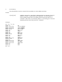
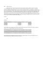
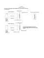
8080 Debug ICE User Manual Code Version 0.32 7/03/2011
Chapter 1
Introduction/Background
The Intel 8080 microprocessor was popular in the mid-to-late 1970’s and was the processor used in the
first examples of what would later be called S-100 computer systems. Once the Z80 was introduced, the 8080
became less attractive as it required three supply voltages, a two-phase clock, and an external status latch. The
Z80 worked off a single +5V supply, required a single clock input, and brought out the necessary status signals
with no latch required. This simplified the design and reduced cost. After designing a simple PIC-based Z80
ICE, I decided to work on an 8080 version as well. Hopefully it will be useful for maintaining and
troubleshooting early 8080-based computer designs. Like the Z80 ICE, it can display memory, write to I/O
ports, etc. (Before I started the Z80 design, I became aware of a product developed in the early 80’s by Nicolet
Paratronics called the Z80 NICE. It offered a lot more capabilities than I had planned to implement, with only a
small increase in component cost. Using the capabilities of this device as a reference, I designed the Z80 ICE,
which is very similar to the 8080 one. I added some new capabilities as well, which I hope will prove useful.
Many thanks to Jeff Jonas for the generous loan of his NICE unit so I could become familiar with it.)
Chapter 2
Setup
The 8080 ICE was designed to be used with either a terminal, or a terminal emulation program such as
TeraTerm or HyperTerm running on a PC or Mac.
Serial settings are 8 data bits, no parity, and 1 stop bit. No hardware handshaking is needed. Note: The
R command can process data and store it in the target system’s memory at up to 19.2 K baud, if the target
system is running at 1 MHz or higher. If a slower 8080 clock is used, higher baud rates can cause a data overrun
condition, which will cause an error message to be displayed. (Using hardware handshake won’t fix this, as the
PC takes too long to react to CTS going inactive.) In this case, simply switch to a slower baud rate.
The ICE automatically detects the baud rate. After powering up the unit, hit Enter on the terminal to
send a carriage return. The ICE uses this to detect the baud rate and set its rate to match. Supported rates are
300, 600, 1200, 2400, 4800, 9600, and 19200 baud. After the ICE has set its baud rate, it will send the sign-on
message. If you don’t see this after pressing Enter, reset or power down the system and try again.
Note: The ICE’s PIC microcontroller is reset by the same active-high signal that resets the 8080. If
there is a problem with the target system that causes this signal to stay high or float, the ICE’s microcontroller
will be held in reset, and will never send anything to the terminal.
The ICE will initially come up in Quit mode. (8080 paused) Press X to dump the registers and see if
everything is OK. If the register display hangs, reset or power down the system and try again.
If you would prefer to have the ICE come up and start running automatically, as a standard 8080 chip
would, use the EA command to enable “AutoRun” mode. This setting will be saved in EEPROM, and the next
time you power up, the 8080 will start executing from address 0 after reset ends. The DA command can be used
to disable AutoRun mode.
Note: In my simple test system, using the ICE instead of the 8080 by itself adds about 100 mA to the
total system current.
Chapter 3
Command Line Interpreter
Commands may be entered in either upper or lower case. All numeric values such as addresses or
counts are entered and displayed in hex. When entering a 16-bit value (d16) 1-4 hex digits can be entered. 1 or
2 digits can be entered for an 8-bit value (d8). If a command accepts parameters it must be followed by a space.
The parameters can be separated by either a comma or a space. Each command must be followed immediately
by either a semicolon or a carriage return.
The command line can hold up to 31 characters. Once that limit is reached, you should hear a beep
from the terminal. Any additional characters entered will replace the last character on the line.
The command(s) on the command line will be executed when a carriage return is typed.
There are two prompts:
OK====> indicates the last command was accepted and executed without error
ERR===> indicates that the last command was either not accepted, or caused
an error when it was executed.
In either case, the ICE is ready for a new command to be entered.
Some commands may take a long time to execute, and you may decide to abort the command.
The following commands may be either paused using Ctl-S, then resumed using Ctl-S or Ctl-Q,
or stopped, by using Ctl-C:
D
L
V
T
U
Display memory
List memory
Verify (compare) memory
Trace
Untrace
It is possible to put more than one command on the same command line. In this case, use a semicolon
instead of carriage return to signal the end of a command. Using the repeat line (RL) command, it is possible to
repeat a sequence of commands in a loop. Delay can be inserted between commands with the Z command.
For example, the command
O 80 A5;Z 10;RL<CR>
will write A5 to I/O address 80, then delay for 16 (0x10) mSec, and repeat. To break out of the loop, press CtlC.
The following commands always end command line processing, and will prevent looping if used in a
command line repeat loop:
G, L, Q, R, S, T, U, W, X
Chapter 4
Overview of Operation
The ICE has two modes of operation – Go mode and Quit mode.
In Go mode, the ICE executes 8080 instructions at full speed, but not all of the commands are available.
Basically, commands that don’t require participation by the 8080 can be executed in this mode, such as enabling
or disabling interrupts or hold requests to the 8080. Breakpoints can be changed in Go mode, since they are not
used in this mode.
In Quit mode, the 8080 is paused, and can be used to implement the full set of commands, such as displaying or
disassembling memory, computing checksums, writing to I/O ports, etc. The Trace and Untrace commands can
be used in Quit mode to execute code, but not at full speed. Since the Trace mode displays all of the registers
after each instruction, its speed is affected by the baud rate being used. This command is always slower than
Untrace. The Untrace command does not display anything after each instruction, but it does grab the current PC
value from the 8080 to check against breakpoints and printpoints. This takes some time. With the 8080 clocked
at 2 MHz, Untrace executes roughly 1600 instructions/second. (This is not fast enough to keep up with data
coming off of a floppy disk, so don’t try to boot from a floppy in untrace mode.)
Interrupts:
The ICE can recognize interrupts in Go mode, but not in Quit mode. In Go mode, the user can enable or disable
interrupts reaching the CPU. In Quit mode, no interrupts can reach the CPU.
Hold Requests:
The ICE can recognize Hold requests in Go mode, but not in Quit mode. In Go mode, the user can enable or
disable Hold requests reaching the CPU. In Quit mode, no Hold requests can reach the CPU.
Reset:
The PIC MCU uses the same reset signal as the 8080, so it comes up in a known state whenever the 8080 gets
reset:
Interrupts are enabled, or will be at least, when Go mode is entered. Hold requests are enabled as well.
The ICE comes up in Quit mode unless Autorun is enabled, then it comes up in Go mode, with the 8080
executing code.
All breakpoint and printpoint enables are cleared
The “saved memory address” is set to 0xFFFF. (More on this later)
The default PC starting value for the next G command is reset to 0000
Since the PIC gets reset whenever the 8080 is reset, you need to send it a carriage return to allow the auto-baud
detection to complete. If characters are not echoed to the terminal after you see the version text displayed, reset
or power down the target system and try again.
Chapter 5
Go Mode Commands
These commands can be entered in either mode (except Q):
BP
BPC
EBP
DBP
EPP
DPP
C
EI
DI
EH
DH
EA
DA
H
CF
Q
RL
ST
Z
-
Set breakpoint (address)
Set breakpoint count
Enable breakpoint
Disable breakpoint
Enable printpoint
Disable printpoint
Clear all breakpoints and printpoints
Enable interrupts
Disable interrupts
Enable hold requests (DMA)
Disable hold requests
Enable start-up Autorun (setting saved in EEPROM)
Disable start-up Autorun (setting saved in EEPROM)
hexadecimal sum and difference
Clock frequency measurement (8080 clock)
Quit (pause 8080)
Repeat (command) line
Status display
Sleep (insert delay)
BP:
(Set breakpoint address)
Sets one of the three breakpoint addresses, which are used by the trace and untrace commands.
Breakpoints end the current trace or untrace command when reached (and enabled) during either of these
commands. They are compared to the current PC after each instruction is executed.
Breakpoints only work in Quit mode. Current breakpoint status can be displayed with the ST command.
Format:
BP n,d16
Example:
OK ====> ST
---> 0ABC 00 D
---> 0246 00 D
---> 0369 00 D
IH
OK ====> BP 1 123
OK ====> BP 2 654
OK ====> BP 3 982
OK ====> ST
---> 0123 00 D
---> 0654 00 D
---> 0982 00 D
IH
OK ====>
n is 1,2 or 3. d16 is a 16-bit address
BPC:
(Set breakpoint pass count)
Sets the pass count for one of the three breakpoint addresses, which are used by the trace and untrace
commands. (Count=0 and count=1 will produce the same result) Setting the count to 3 will cause a trace to
stop on the third time that breakpoint matches the current PC. (If it is enabled)
If the pass count does not reach zero while a trace or untrace command is executing, its value is
preserved and can be examined with the ST command to see how many times that breakpoint was hit. So if the
pass count was set to 10 at the start of the command and is 7 after the trace or untrace stops, that address was hit
3 times.
Format:
BPC n,d8
Example:
OK ====> ST
---> 0123 00 D
---> 0654 00 D
---> 0982 00 D
IH
OK ====> BPC 1,33
OK ====> BPC 2,66
OK ====> BPC 3,99
OK ====> ST
---> 0123 33 D
---> 0654 66 D
---> 0982 99 D
IH
OK ====>
n is 1,2 or 3. d8 is an 8-bit count
EBP:
(Enable breakpoint(s))
Enables one of the three breakpoints, which are used by the trace and untrace commands. If no
parameter is entered, all three breakpoints will be enabled.
Format:
EBP [n]
DBP:
n is 1,2 or 3
(Disable breakpoint(s))
Disables one of the three breakpoints, which are used by the trace and untrace commands. If no
parameter is entered, all three breakpoints will be disabled.
Format:
DBP [n]
Example:
OK ====> ST
---> 0123 33 D
---> 0654 66 D
---> 0982 99 D
IH
OK ====> EBP
OK ====> ST
---> 0123 33 E
---> 0654 66 E
---> 0982 99 E
IH
OK ====> DBP 3
OK ====> ST
---> 0123 33 E
---> 0654 66 E
---> 0982 99 D
IH
OK ====>
n is 1,2 or 3
EPP:
(Enable printpoint(s))
Enables one of the three printpoints, which are used by the trace and untrace commands. If no
parameter is entered, all three printpoints will be enabled.
Printpoints cause the current 8080 register values to be displayed when reached (and enabled) during an
untrace command. They are compared to the current PC after each instruction is executed.
Note that printpoints and breakpoints share the same three address values, so a particular address can be
enabled as a breakpoint, a printpoint, or both. (Breakpoint pass count values don’t affect printpoint operation.)
Format:
EPP [n]
DPP:
n is 1,2 or 3
(Disable printpoint(s))
Disables one of the three printpoints, which are used by the trace and untrace commands. If no
parameter is entered, all three printpoints will be disabled.
Format:
DPP [n]
Example:
OK ====> EPP
OK ====> ST
---> 0123 33 E P
---> 0654 66 D P
---> 0982 99 E P
IH
OK ====> DPP 2
OK ====> DPP 3
OK ====> ST
---> 0123 33 E P
---> 0654 66 D
---> 0982 99 E
IH
OK ====>
n is 1,2 or 3
EI:
(Enable interrupts)
Enables interrupts to reach the 8080 when in Go mode. If this command is entered while the CPU is in
Go mode, interrupts will be enabled immediately. An “I’ appears on the last line of the status display if
interrupts are currently enabled. (Interrupts are always disabled in Quit mode, even if an I is displayed)
Format:
EI
DI:
(Disable interrupts)
Prevents interrupts from reaching the 8080 when in Go mode. If this command is entered while the
CPU is in Go mode, interrupts will be disabled immediately.
Format:
EI
Example:
OK ====> ST
---> 0123 33 E P
---> 0654 66 D P
---> 0982 99 E P
IH
OK ====> DI
OK ====> ST
---> 0123 33 E P
---> 0654 66 D P
---> 0982 99 E P
H
OK ====> EI
OK ====> ST
---> 0123 33 E P
---> 0654 66 D P
---> 0982 99 E P
IH
OK ====>
EH:
(Enable hold requests)
Enables hold requests to reach the 8080 when in Go mode. If this command is entered while the CPU is
in Go mode, hold requests will be enabled immediately. An “H’ appears on the last line of the status display if
hold requests are currently enabled. (Hold requests are always disabled in Quit mode, even if an H is displayed)
Format:
EH
DH:
(Disable hold requests)
Disables hold requests from reaching 8080 when in Go mode. If this command is entered while the
CPU is in Go mode, hold requests will be disabled immediately.
Format:
DH
Example:
OK ====> ST
---> 0123 33 E P
---> 0654 66 D P
---> 0982 99 E P
IH
OK ====> DH
OK ====> ST
---> 0123 33 E P
---> 0654 66 D P
---> 0982 99 E P
I
OK ====> EH
OK ====> ST
---> 0123 33 E P
---> 0654 66 D P
---> 0982 99 E P
IH
OK ====>
EA:
(Enable Autorun)
Enables Autorun after power-up or reset. This setting is saved in EEPROM and will be maintained even
when power is removed. Enabling Autorun causes the 8080 to immediately start executing code from address 0
at power-up. The ICE is in Go mode at this point. Interrupts and hold requests are enabled. The current
Autorun setting is part of the status display.
Format:
EA
DA:
(Disable Autorun)
Disables Autorun after power-up or reset. This setting is saved in EEPROM and will be maintained
even when power is removed. Disabling Autorun causes the ICE to enter Quit mode at power-up until a G
command is executed.
Format:
DA
Example:
OK ====> EA
OK ====> ST
---> 0000 00 D
---> 0000 00 D
---> 0000 00 D
IHA
OK ====> DA
OK ====> ST
---> 0000 00 D
---> 0000 00 D
---> 0000 00 D
IH
OK ====>
H:
(Hex “calculator”)
Computes hexadecimal sum and difference. If values entered are A and B, in that order,
command displays A+B, A-B. Results are limited to 16 bits and will wrap above 0xFFFF.
Format:
H d16,d16
Values entered as 1-4 hex digits.
Example:
OK ====> H 10A5,674C
77F1,A959
OK ====> H FFFE,0002
0000,FFFC
OK ====> H 2000,1000
3000,1000
OK ====>
CF:
(Clock frequency)
Measure the frequency of the 8080 clock. Value displayed can have up to 1 part in
256, or about 0.4% error. Minimum displayable clock rate is ~ 19 KHz.
Format:
CF
Example:
OK ====> CF
8080 clock frequency is ~ 1.993 MHz
OK ====>
Q:
(Quit)
Quit (stop 8080 and enter Quit mode)
Format:
Q
Example:
OK ====> Q
.Z...
OK ====>
A=00
BC=1234
DE=F74C
HL=5542
S=FFF0
P=824D
MOV A,L
RL
(Repeat Line)
This command may be used to repeat a command or group of commands on a single command line.
This could be used together with the sleep command to create a repetitive write to the same memory location,
for instance, so that an oscilloscope can be used to observe timing and signal behavior. To break out of the loop,
press Ctl-C.
Example:
OK ====>
P 8000 A5;Z 9;RL
Above command line will write 0xA5 to address 0x8000 then it will delay for 9 mSec, then repeat.
ST
(Status)
Display breakpoint/printpoint and hardware status. The first three lines of the status display are
devoted to breakpoint/printpoint information. The first value is the address which will be compared to the PC.
The second value is the breakpoint pass count. The third value is either a D or E which indicates whether that
address and pass count are currently enabled (E) or disabled (D) as a breakpoint. The fourth value, if displayed,
is a P if the address is currently enabled as a printpoint.
The fourth line shows the current states of the two hardware enables. If interrupts are enabled, an I will
be displayed. If Hold requests are enabled, an H will be displayed. Note that both of these are always disabled
in Quit mode, regardless of what is displayed. If start-up Autorun is enabled, an A will also be displayed.
Finally, if the 8080 is currently executing instructions at full speed (a Go command has been issued) the word
Running will be displayed.
Format:
ST
Example:
OK ====> ST
---> 0123 33 E P
---> 0654 66 D P
---> 0982 99 E P
IH
OK ====> G
Execution begins at ====> 473F
OK ====> ST
---> 0123 33 E P
---> 0654 66 D P
---> 0982 99 E P
IH Running
OK ====>
Z
(Sleep)
Causes the command processor to insert a variable delay before processing any other commands.
Format:
Z d8
The parameter is used to specify the desired delay in mSec.
Chapter 6
Quit Mode Commands
These commands can only be used in Quit mode:
CS
D
E
F
G
I
L
M
MT
O
P
R
S
SR
T
U
V
W
X
-
Generate and display 16-bit checksum of memory region
Display memory
Examine a single memory location (intended for ‘scope loops)
Fill memory
Go
Input from I/O port
List (disassemble) memory
Move memory block
Memory test (destructive)
Output to I/O port
Put data into a single memory location (intended for ‘scope loops)
Read Intel Hex file into memory
Substitute into memory
Soft reset
Trace
Untrace
Verify
Write Intel Hex file from memory
Examine/change registers
CS:
(Checksum memory region)
Adds memory contents from start address to end address (inclusive) and displays 16-bit sum.
The result may exceed 16 bits, but only the low 16-bits are displayed. This should match the checksum
generated by many EPROM programmers. CS can also be used to check how reliable EPROM memory reads
are by repeating the command and comparing the results.
Format:
CS start,end
Addresses entered as 1-4 hex digits.
Format:
CS
Example:
OK ====> CS 0000,03FF
Checksum: 0x73FD
OK ====>
D:
(Display memory)
Displays memory contents from start address to end. Start address is truncated so that display always
starts at nnn0. Multiples of 16 bytes are displayed, until end address is reached (or passed). ASCII equivalents
for the data are also displayed. A dash is inserted after the first 8 bytes.
Format:
D [start],[end]
Addresses entered as 1-4 hex digits. Both parameters are optional. If no end
address is entered, 0x80 bytes are displayed. If no start address is entered,
display begins at the next address after the end of the last D or L command.
(This is the “saved memory address”) So entering just D will start displaying
from the end of the previous D command.
Example: (ASCII section is not correct)
OK ====> D 0002,0019
0000
0010
C3 F1 A5 26 72 89 CE 27-F3 06 82 01 CD 00 77 BC
3C 1F 5A 62 CE 98 CE 27-F3 06 82 01 CD 00 77 BC
....This text do
es not go with t
C3
3C
C3
3C
C3
3C
C3
3C
he data on the l
eft.............
.I once shot an.
elephant in my.p
ajamas. What he.
was doing in my.
pajamas I’ll nev
er know.........
OK ====> D
0020
0030
0040
0050
0060
0070
0080
0090
F1
1F
F1
1F
F1
1F
F1
1F
A5
5A
A5
5A
A5
5A
A5
5A
26
62
26
62
26
62
26
62
72
CE
72
CE
72
CE
72
CE
89
98
89
98
89
98
89
98
CE
CE
CE
CE
CE
CE
CE
CE
27-F3
27-F3
27-F3
27-F3
27-F3
27-F3
27-F3
27-F3
06
06
06
06
06
06
06
06
82
82
82
82
82
82
82
82
01
01
01
01
01
01
01
01
CD
CD
CD
CD
CD
CD
CD
CD
00
00
00
00
00
00
00
00
77
77
77
77
77
77
77
77
BC
BC
BC
BC
BC
BC
BC
BC
E:
(Examine a single memory location)
Read 8-bit data from selected 8080 memory address and display it. This command reads from a single
8080 memory location, unlike the D command, and is useful for creating a repeated memory read
operation with the Z and RL commands, so that target system signals can be examined with a nonstorage oscilloscope.
Format:
E address
16-bit memory address entered as 1-4 hex digits.
F:
(Fill memory)
Fills memory from start address to end with the value given.
Format:
F start,end,value
Addresses entered as 1-4 hex digits. Value is 1-2 hex digits. Same value is
written to every location. No attempt is made to verify that the write
succeeded.
G:
(Go)
Go (Start 8080 CPU executing at full speed)
Format:
G [starting address]
Starting address entered as 1-4 hex digits. If no starting
address is entered, current PC value is used.
I:
(Input from I/O port)
Input 8-bit data from selected 8080 I/O port and display it
Format:
I address
8-bit I/O address entered as 1-2 hex digits.
L:
(List memory)
Lists (disassembles) memory contents from start address to end as 8080 instructions.
Format:
L [start],[end]
Addresses entered as 1-4 hex digits. Both parameters are optional. If no end
address is entered, 19 instructions will be displayed. If no start address is
entered, display begins at the next address after the end of the last D or L
command. (This is the “saved memory address”) So entering just L will start
displaying from the end of the previous L command.
Example:
OK ===>
0000 F3
0001 31
0004 21
0007 01
000A 1E
000C 7E
000D 81
000E 4F
000F 78
0010 CE
0012 47
0013 23
0014 1D
0015 C2
0018 D3
001A 00
001B C3
001E CC
0021 C4
0024 00
0025 00
OK ===>
l 0 25
F0 80
00 00
00 00
1A
00
0C 00
00
00 00
0C 00
1A 00
DI
LXI SP,#80F0
LXI H,#0000
LXI B,#0000
MVI E,#1A
MOV A,M
ADD C
MOV C,A
MOV A,B
ACI #00
MOV B,A
INX H
DCR E
JNZ 000C
OUT 00
NOP
JMP 0000
CZ 000C
CNZ 001A
NOP
NOP
M:
(Move memory block)
Moves a block of memory data from one area of memory to another. The destination area must be
writeable for the command to work, but no attempt is made to confirm that the write actually succeeded.
Format:
M start,end,dest
The block of data between start and end (inclusive) is copied to a new area of
memory, starting at dest.
MD:
(Memory detect)
Reads and writes 16 bytes at start of all 64 1K pages of target memory and tries to detect read-only
memory and RAM. If data always reads the same despite writing several patterns, we assume its read-only
memory. If data always matches what we wrote, we assume it’s RAM. Data in each 1K page is compared with
data in lower 1K pages to detect stuck or unconnected upper address bits or the same memory appearing several
times in the memory space. Page number displayed is lowest 1K page in target memory that contains the same
data as this one. If no memory repeats, then each page will display its own page number. Note that if the bus
always floats to the same value, or is terminated to a logic one level when floating, the data will always read the
same, so it will be detected as read-only memory. Note: Executing this command will write to the first 16 bytes
of every page, so memory contents will be changed.
Format:
MD
Example:
0000000000000000111111111111111122222222222222223333333333333333
0123456789ABCDEF0123456789ABCDEF0123456789ABCDEF0123456789ABCDEF
RRRRRRRR
RRRRRRRR
RRRRRRRR
OOOOOOOO
OOOOOOOO
WWWWWWWW
00000000
00000000
33333333
01234567
01234567
89ABCDEF
Above display shows 8K Read-only memory located in first eight 1K pages, and the same memory appears at
32K as well. An 8K RAM appears only in the top 8K pages.
0000000000000000111111111111111122222222222222223333333333333333
0123456789ABCDEF0123456789ABCDEF0123456789ABCDEF0123456789ABCDEF
RRRRRRRRRRRRRRRRRRRRRRRRRRRRRRRRRRRRRRRRRRRRRRRRRRRRRRRRRRRRRRRR
WWWWWWWWWWWWWWWWWWWWWWWWWWWWWWWWWWWWWWWWWWWWWWWWWWWWWWWWOOOOOOOO
0000000000000000111111111111111122222222222222223333333333333333
0123456789ABCDEF0123456789ABCDEF0123456789ABCDEF0123456789ABCDEF
Above display shows 8K Read-only memory located in top eight 1K pages. The rest of the address space is
filled with RAM that is fully decoded. (Does not repeat)
MT:
(Memory test)
Performs a destructive test of memory by writing a rotating pattern of first a single 1 bit, then a single 0
bit and the rest ones to each memory location in the indicated range. After the pattern is written to the entire
area, all locations are checked to see if the value read matches what was written. Any mismatches are displayed
as address, value written, value read. The entire memory range is written and read 16 times, so any particular
address may appear in the error list up to 16 times, if it fails for all data values.
Format:
MT start,end
O:
(Output to I/O port)
Write 8-bit data entered to selected 8080 I/O port
Format:
O port #,d8
8-bit I/O port number/address entered as 1-2 hex digits.
P:
(Put (write) data into a target system memory location)
Write 8-bit data entered to selected 8080 memory location. This command writes to a single memory
location, and is useful for creating a repeated memory write operation with the Z and RL commands, so
that target system signals can be examined with a non-storage oscilloscope.
Format:
P address,d8
16-bit memory address entered as 1-4 hex digits.
R:
(Read Intel Hex file into memory)
Used to load target system memory with test programs, etc, saved in Intel Hex format. An optional 16bit offset may be entered. This offset will be added to the addresses in the Hex file before storing the file data in
memory. This is useful if the code being loaded is relocatable. If no offset is entered, an offset of 0 is used.
(No offset)
The R command can process data and store it in the target system’s memory at up to 19.2 K baud, if the
target system is running at 1 MHz or higher. If a slower 8080 clock is used, higher baud rates can cause a data
overrun condition, which will cause an error message to be displayed. (Using hardware handshake won’t fix
this, as the PC takes too long to react to CTS going inactive.) In this case, simply switch to a slower baud rate.
Format:
R [d16]
S:
(Substitute into memory)
Used to load hex data values into system memory. No attempt is made to determine if write to memory
was successful, so you can substitute into EPROM, but it won’t accomplish much.
Format:
S d16
To advance to next address without changing contents, hit CR. To back up to previous
address, hit a dash (-). To exit substitute memory mode, hit a period (.).
SR:
(Soft reset)
Causes the ICE to reset all of the 8080’s registers to zeroes.
Format:
SR
T:
(Trace)
This command may be used to step through target system code one instruction at a time. The 8080’s
internal registers are displayed after each instruction. An optional parameter may be entered to specify a
number of instructions to be executed. Entering T 10 will execute 10 instructions and then stop. If an enabled
breakpoint is reached before 10 instructions have executed, the trace will stop immediately. If the number of
instructions to execute is entered as 0, the trace instruction will continue until a breakpoint is hit, and will not
count instructions. If no parameter is entered, only one instruction will be executed.
If the 8080 encounters a Halt instruction when tracing, it will stop fetching opcodes and will no longer
be controllable by the ICE. A message will be displayed in this case, and the system will need to be reset to
restore normal operation.
Format:
T [d16]
U:
(“Untrace”)
This command is similar to the trace command, but the registers are not displayed after every
instruction, so execution is much faster. The registers may be displayed when specific PC values are hit using
printpoints. Untracing will stop if the requested number of instructions has been executed, or if an enabled
breakpoint has been reached. A parameter must be entered to specify a number of instructions to be executed.
Entering U 10 will execute 10 instructions and then stop and display the registers. If an enabled breakpoint is
reached before 10 instructions have executed, the untrace will stop immediately. If the number of instructions
to execute is entered as 0, the untrace instruction will continue until a breakpoint is hit, and will not stop based
on instruction count. When the untrace command stops, the total number of instructions executed during this
one command is displayed. This could be used to count, for instance, how many 8080 instructions are executed
between system reset and a prompt appearing. Ctl-C can also be used to stop the untrace command.
If the 8080 encounters a Halt instruction when untracing, it will stop fetching opcodes and will no
longer be controllable by the ICE. A message will be displayed in this case, and the system will need to be reset
to restore normal operation.
During an untrace command, the 8080’s PC is monitored and when instructions that modify it, such as
branches, calls, and returns are executed, their address is saved in a 12-entry FIFO buffer. When the untrace
command stops, these instructions are displayed above the CPU registers, and can be used to trace backwards
from the current PC value to see what the recent sequence of calls or branches was before we stoppped. A
maximum of 12 of these instructions will be displayed. If fewer than 12 were executed during the current
untrace command, only that number will be displayed.
Format:
U d16
V
(Verify/compare memory)
This command will verify/compare two regions of memory and display any differences found.
Differences will be displayed as: address in first region, value in first region, value in second region.
Format:
V start,end,dest
Parameters are d16. All bytes from start to end (inclusive) will be compared.
W
(Write memory out as Intel Hex file)
Used to save target system EPROM images, etc, in Intel Hex format. A 16-bit offset must be entered.
This offset will be added to the addresses in the Hex file before storing the file data in memory. This may be
useful if the code is located at an address other than 0, but you want the Intel Hex file addresses to start at 0 for
loading into an EPROM programmer, for instance. Offset addition will wrap at 64K, so 0xF000 + 0x1000 =
0x0000. If you don’t want any offset, just enter 0.
Format:
W start,end,offset
Parameters are d16. All bytes from start to end (inclusive) will be written.
Start must be a lower address than end.
X
(Examine and edit the contents of the 8080’s registers)
Used to display or change 8080 register contents. Valid register selection arguments are:
F, A, B, D, H, S, P. HL, BC, and DE must be edited as a 16-bit pair.
Format:
X [regsel]
If no register selection argument is enterred, the complete register set will be displayed
Example:
OK ====> x
.Z...
OK ====>
A=00
BC=1234
DE=F74C
HL=5542
S=FFF0
P=824D
MOV A,L
Chapter 7
Cabling Information:
Chapter 8
How does it work?
The ICE consists of a 2 MHz 8080 CPU, a 74HC4049 level shifter chip, a CPLD custom logic chip, an
RS-232 level translator/charge pump chip, and a PIC microcontroller. The PIC chip communicates with a
terminal through the RS-232 chip and controls the 8080. It is capable of reading 8080 register values, loading
the 8080’s registers, single-stepping the 8080 through code, starting the 8080 running at full speed, and stopping
the 8080. The CPLD chip contains logic to allow the PIC to control the 8080 and also to inhibit the hold request
and interrupt signals from reaching the 8080. It can also prevent the 8080’s DBIN, and WRb signals from
reaching the target system. In Quit mode, these two signals are forced to their inactive state in the target system,
to insure that the target system is not using the data bus. This is necessary as the data bus is used for PIC-to8080 communication in this mode. In Go mode, the PIC chip starts up the 8080 and lets it run. In this mode,
the ICE operates just like a normal 8080 chip. In Quit mode, the 8080 has been paused, and can be used to
implement the commands that give the ICE its power. All communication with the target system’s memory
takes place through the 8080. To read data from a memory location, the PIC arranges for the 8080 to read from
that location, and then hand the data to the PIC. If the 8080 is halted, it is not fetching op codes, and cannot be
controlled by the PIC chip. This condition is detected and a message is displayed. The system must be reset to
restore normal operation. The 74HC4049 chip converts the 0-12V PHI 1 and PHI 2 8080 clock signals into 05V signals that can be fed into the CPLD.
Chapter 9
Watchdog Timer - 8080 Reset Issue
Some 8080-based designs may have a circuit called a “watchdog timer”. When code is executing
normally, the 8080 writes to or reads from a particular I/O or memory address maybe a few times each second.
This action resets the timer and maintains normal operation. If the CPU crashes, it stops resetting the timer. As
a result, the timer reaches a preset count, which causes the RESET input to the 8080 to go high, resetting the
CPU and restoring normal operation of the system. If an ICE is used, since the 8080 is paused a lot of the time,
the watchdog timer will not get reset, and will keep resetting the 8080 (and the PIC chip), perhaps five
times/second or faster. The ICE can’t work if it keeps getting reset. There are two ways that the ICE can be
used in systems with a watchdog timer:
1) Disable the watchdog timer. Some boards may have a jumper on the main board that can be used for
this purpose. You may need to solder across two pads temporarily to disable the timer. Other systems
may have a different way to disable the timer (or no way at all).
2) Modify the ICE to supply its own RESET signal to the 8080 and the PIC chip. If you do this, you’ll
need to cycle power to the ICE to reset it, since any target system reset switch will no longer function.
Provision has been made on the pc board for an optional reset circuit. To use this circuit, open jumper
JP1, which is normally shorted, and install C17, R1, and D1. (These components are normally not
installed.) The values shown on the schematic for R1 and C17 have not been tested, and may need to be
adjusted for reliable operation. D1 prevents C17 from discharging into the CPLD and 8080 when power
is removed.
3) Chapter 10
Code with a Halt Instruction
The PIC controls the 8080 by feeding it opcodes. When the 8080 executes a Halt instruction, it stops
fetching opcodes and waits for an interrupt or reset. Some code may normally sit in a halted state waiting for an
interrupt, then perform some action such as checking for a key press, serial character received, etc, then after
any required tasks have been performed, execute a halt and wait for the next interrupt. The ICE will not work
properly when executing this type of code, as the 8080 stops fetching instuctions when halted, and cannot be
controlled by the PIC. The ICE can still be used in this type of system, but the code containing the Halt
instruction cannot be executed. To avoid executing the Halt instruction as soon as the system is powered up,
disable “autorun” mode, so that the 8080 will come up paused after reset. To do this, reset the system, hit
<Enter> to get the sign-on message and prompt, then type
DA <Enter>
This will disable autorun mode. (This setting is saved in EEPROM.) Now reset the system, and hit <Enter> to
get the sign-on message and prompt. Now you should be able to use the ICE to test memory, access I/O ports,
etc, but don’t execute the code that includes the Halt instruction, as the ICE won’t work after that.
Chapter 11
Differences between this unit and Nicolet’s Z80 NICE
New commands not present in NICE:
CF - Measure clock frequency
CS - form 16-bit checksum of memory block
E - Examine and display a single memory location, for scope loops
MD - Try to detect RAM and EPROM in target memory space
P - Put data into a single memory location, for scope loops
W - Write out memory as Intel Hex
EA, DA - control start-up behavior (Go or Quit)
? - display help screen with command list
Other differences:
L command displays hex data bytes along with instructions
L command resolves branch target addresses
M command checks for overlap between source and destination regions and changes move order if nec.
U command displays branch trace instead of the last few PC values as “backtrace”
U and T commands check for # of instructions = 0, which disables instruction count limit.
U command displays total instructions executed since start of command.
8080 HLTA halt status bit is monitored and a message is displayed if CPU is halted.
IC sockets enable using different 8080 chips, or replacing PIC or RS-232 chip if damaged.
RS-232 level translator chip is used to provide better voltage levels to PC or terminal. NICE uses 5V
and Gnd.
R command (read Intel Hex) can operate at higher baud rates. The manual for the NICE unit implies
that a maximum of 300 baud can be supported without hardware handshaking. I haven’t seen any
problems loading files at much higher baud rates, with no hardware handshake.
Operating current - NICE draws about 500 mA from the Z80 socket. My unit draws much less. The
PALs and MCU used in the NICE draw much more current than the CPLD and PIC chip.
NICE supports assembly of instructions into RAM. (I don’t) This is a nice feature, (no pun
intended) but a lot of work, which I couldn’t justify. It didn’t seem useful enough to warrant the effort.