1
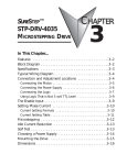
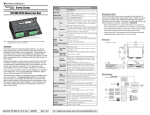
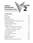
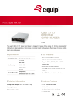
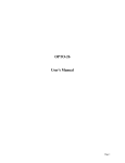
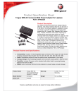
Sure Step™ Microstepping Drive Specifications
STEPPING SYSTEMS
STP-DRV-4035
Microstepping Drive
Power
Connector
Part Number
Input Power
(with red Power On LED)
Pulse Signal
Motor steps on falling edge of pulse and minimum pulse width
is 0.5 microseconds
WARNING: When connecting a step motor to the STP-DRV-4035
drive, be sure that the motor power supply is switched off. When
using a motor not supplied by AUTOMATIONDIRECT, secure any
unused motor leads so that they can’t short out to anything. Never
disconnect the motor while the drive is powered up. Never connect
the motor leads to ground or directly to the power supply. (See the
Typical Wiring Diagram on the back side of this data sheet for the
step motor lead color code of AUTOMATIONDIRECT supplied motors.)
Direction
Signal
Needs to change at least 2 microseconds before a step pulse is sent
Connecting the Logic
12-42 VDC (including ripple voltage)
Output Power
Output current selectable from 0.4 to 3.5 Amps/phase motor current
(maximum output power is 140 W)
Current Controller
Input Signal
Circuit
Dual H-bridge Bipolar Chopper (3-state 20 kHz PWM with MOSFET switches)
Input
Signals
Motor
Connector
Connecting the Motor
STP-DRV-4035
Opto-coupler input with 440 Ohm resistance (5 to 15 mA input current), Logic
Low is input pulled to 0.8 VDC or less, Logic High is input 4 VDC or higher
0 will disable current to the motor
Enable Signal Logic
(current is enabled with no hook-up or logic 1)
Self Test
Mounting
Hole (1 of 6)
Switches for
Selecting Current,
Step Resolution,
Current Reduction
and Self Test
Power On
LED
Logic
Connector
(STEP+/-, DIR+/-, EN+/-)
Note: The Microstepping Drive works with 4, 6 and 8 lead bipolar step motors.
WARNING
To minimize the risk of potential safety problems, you should follow
all applicable local and national codes that regulate the installation
and operation of your equipment. These codes vary from area to area
and it is your responsibility to determine which codes should be
followed, and to verify that the equipment, installation, and operation
are in compliance with the latest revision of these codes.
Equipment damage or serious injury to personnel can result from the
failure to follow all applicable codes and standards. We do not guarantee
the products described in this publication are suitable for your particular
application, nor do we assume any responsibility for your product design,
installation, or operation.
Sheet 1 of 2
STP-DRV-4035
V–
Current
0.4 to 3.5
A/Phase
Self Test
Internal to the
STP-DRV-4035
220 ohms
STEP–
Drive Input Circuit
You will need to supply a source of step pulses to the drive at the
STEP+ and STEP– terminals and a direction signal at the DIR+ and
DIR– terminals, if bidirectional rotation is required.
The ENABLE input allows the logic to turn off the current to the step
motor by providing a signal to the EN+ and EN– terminals. If you do
not have a need to disable the output to the step motor, just leave the
EN+ and EN– terminals disconnected.
All logic inputs can be controlled by a DC output signal that is either
sinking (NPN), sourcing (PNP), or differential.
Connecting to an Indexer with Sinking Outputs
Step+
Step–
Dir+
220 ohms
STEP+
Below and on the back of this data sheet are examples for connecting
various forms of outputs from both indexers and PLCs.
V+
Connect to
Power Supply
(12 - 42 VDC)
Microstep
Sequencer
Optical
Isolation
A+
MOSFET
Amplifier
Dir–
+5V OUT
A–
Indexer
with
Sinking
Outputs
B+
B–
Steps/Rev:
1/2, 1/5,
1/10 or 1/50
Enable+
Enable–
Logic Connections
from PLC or Indexer
The STP-PWR-3204 power supply
from AUTOMATIONDIRECT is the best
choice to power the step motor drive.
Step Motor
Power Supply
12 - 42 VDC
DIR+
DIR–
STP-DRV-4035
Drive
STEP+
EN+
STEP–
EN–
N/C
N/C
Connections
to Bipolar
Step Motor
Connecting to an Indexer with Sourcing Outputs
50% Idle
Current Reduction
Connecting the Power Supply
DIR
STEP
+
Fuse *
–
–
Data Sheet: STP-DRV1-DS, 1st Ed, Rev H – (07/2011)
Block Diagram
VDC
This publication is based on information that was available at the
time it was printed. At Automationdirect.com® we constantly strive to
improve our products and services, so we reserve the right to make
changes to the products and/or publications at any time without
notice and without obligation. This publication may also discuss
features that may not be available in certain revisions of the product.
DIP Switch Microstepping 400 (200x2), 1,000 (200x5), 2,000 (200x10), or 10,000 (200x50) steps/rev
Selectable Idle Current
0% or 50% reduction
(idle current setting is active if motor is at rest for 1 second or more)
Functions Reduction
Phase Current
0.4 to 3.5 Amps/phase with 32 selectable levels
Setting
Natural convection (mount drive to metal surface if possible)
Drive Cooling Method
3 x 4 x 1.5 inches [76.2 x 101.6 x 38.1 mm]
Dimensions
Use #4 screws to mount on wide side (4 screws) or narrow side (2 screws)
Mounting
Screw terminal blocks with AWG 18 maximum wire size
Connectors
9.3 oz. [264g]
Weight
-20–80 °C [-4–176 °F]
Storage Temperature
Chassis Operating
0–55 °C [32–131 °F] recommended; 70 °C [158 °F] maximum
(use fan cooling if necessary); 90% non-condensing maximum humidity
Temperature
CE (complies with EN55011A and EN50082-1 (1992)); RoHS
Agency Approvals
+
If you have any questions concerning the installation or operation of
this equipment, or if you need additional information, please call us
at 770-844-4200.
Off or On (uses half-step to rotate 1/2 revolution in each direction
at 100 steps/second)
The logic inputs are optically isolated to
prevent electrical noise problems to the
drive. The logic inputs require using DC
power from a different supply source
than what is used to power the step
motor power circuits. A schematic
diagram of the input circuit is shown to
the right.
Indexer
with
Sourcing
Outputs
COM
DIR–
DIR
DIR+
STP-DRV-4035
Drive
STEP–
EN+
STEP+
EN–
N/C
STEP
N/C
* External fuse not req'd when using the
STP-PWR-3204 P/S, fuse is internal.
If the power supply you choose does not have a fuse on the output,
you will need to install a 4 amp fast acting fuse on the “+” power
supply lead as shown in the above diagram.
WARNING: Be careful not to reverse the polarity from the power
supply to the drive. Reverse connection will destroy your drive and
void the warranty.
For a complete user manual, please visit www.automationdirect.com
Connecting to an Indexer with Differential Outputs
DIR+
Indexer
DIR–
with
Differential
Outputs STEP+
STEP–
DIR+
DIR–
STP-DRV-4035
Drive
STEP+
EN+
STEP–
EN–
N/C
N/C
Current Setting Table
R
R
(If enable function is used)
STEP–
EN–
STEP+
EN+
AMPS/ 0.4
PHASE 0.8
AMPS/ 0.4
PHASE 0.8
1.6
(If enable function is used)
Setting Phase Current
0.1
0.2
AMPS/ 0.4
PHASE 0.8
1.6
1.1
0.1
0.2
AMPS/ 0.4
PHASE 0.8
1.6
1.9
1.6
AMPS/ 0.4
PHASE 0.8
0.1
0.2
AMPS/ 0.4
PHASE 0.8
1.6
AMPS/ 0.4
PHASE 0.8
2.6
0.1
0.2
2.7
Data Sheet: STP-DRV1-DS, 1st Ed, Rev H – (07/2011)
0.1
0.2
3.4
1.6
0.1
0.2
3.5
1.6
The microstepping drive has a built-in feature that will reduce the
motor current by 50% anytime the motor is not moving. Drive
heating is reduced by about 50% and the feature lowers motor
heating by 75%. Slide DIP switch position 4 toward the label marked
“50% Idle” to enable this feature. Please be aware that when this
feature is used, holding torque is reduced.
50% IDLE
50% IDLE
Idle Current Reduction
Selected
(Factory Default)
A+
A–
B+
Cable Color Code
Term Wire Pin #
1
A+
Red
2
A– White
B+ Green 3
B– Black
4
B–
Extension Cable
STP-EXT-020
Stepper Drive
12" Motor Pigtail
with Connector
Step Motor
STP-MTR-xxxxx
Connector
Mounting the Drive
The microstepping drive can be mounted on either the wide or the
narrow side of the chassis using #4 screws. The wide side requires four
screws, while the narrow side requires two screws.
WARNING: Never use the drive in a space where there is no air flow
or the surrounding air temperature is greater than 70 °C.
Wide Side Mount
Narrow Side Mount
Smooth Flat Surface
#4 Screws
Unless you are running at 1 Amp/phase motor current or below,
you may need a heat sink. Often, the metal subpanel being
used for the control system will make an effective heat sink.
Dimensions
1.50
[38.1]
0.125
[3.2]
2.50
[63.5]
4x Ø0.125
[Ø3.2]
2x Ø0.125
[Ø3.2]
3.70
[94.0]
3.75
[95.3]
4.00
[101.6]
Self Test
The microstepping drive includes a self test feature. This feature can
be used for trouble shooting your system. Slide DIP switch position
1 toward the label marked “TEST” and the step motor will slowly
rotate 1/2 revolution forward and then 1/2 revolution backward. This
motion will repeat until the DIP switch is returned to the off position.
The self test will use half step mode and ignore any input signals on
the STEP and DIR terminals. The ENABLE input will continue to
function normally.
TEST
TEST
Self Test OFF
(Factory Default)
Sheet 2 of 2
VDC –
No Current Reduction
Self Test ON
1/2
1/10
1/5
1/2
1.6
1
1/5
1/50
1/10
1/50
1.6
0.1
0.2
3.3
VDC +
+
4
10,000
STEPS/REV
(1/50)
0.1
0.2
1
1/5
1/50
1/10
1/50
1/5
1/50
1/10
1/50
1.8
1.6
4
1/2
1/10
1/5
1/2
STEPS/REV
(1/10)
1/2
1/10
1/5
1/2
2 3
1,000
STEPS/REV
(1/5)
2,000
2 3
Factory
Default
1/5
1/50
1/10
1/50
2 3
STEPS/REV
(HALF)
1/2
1/10
1/5
1/2
2 3
400
AMPS/ 0.4
PHASE 0.8
1.6
0.1
0.2
AMPS/ 0.4
PHASE 0.8
2.5
–
STP-PWR-3204
Idle Current Reduction
Microstepping
The microstepping drive has the ability to be set up for more than just
the normal full and half step resolutions found in other drives. This
ability is referred to as microstepping. It is accomplished by precisely
controlling the amount of current in each phase at each step position
and allows the steps to be electronically subdivided even further. The
drive can be set up for either half step or three microstep resolutions,
1/5, 1/10 or 1/50 microsteps. In a typical 1.8° step motor, this will
equate to 1,000, 2,000 or 10,000 steps per revolution. DIP switch
positions 2 and 3 are used to set the resolution as shown below:
AMPS/ 0.4
PHASE 0.8
STP-DRV-4035
Typical Wiring
Diagram
STPDRV-4035
5 6 7 8 9
5 6 7 8 9
Locate the 9 position DIP switch on the drive.
0.1
The last five positions, 5-9, have a value of
0.2
0.4
current printed adjacent, and are used to set the
0.8
motor phase current. There is always a base
1.6
current of 0.4 A. To add to the base current, slide
the appropriate switches toward their labels marked on the drive’s PC
board.
Example: 2.2 Amps = 0.4 (base current) + 1.6 + 0.2
1.6
0.1
0.2
5 6 7 8 9
Current Setting Formula
0.1
0.2
5 6 7 8 9
Set the drive to the proper motor phase current before applying power
to the drive. The rated current is usually printed on the step motor
label. Setting the DIP switches for the rated current can be achieved
by either following the simple formula that follows below or skipping
to the Current Setting Table shown to the top right and setting the
DIP switch positions to match what is shown in the table for the
current.
1.0
AMPS/ 0.4
PHASE 0.8
1.7
Factory
Default
5 6 7 8 9
0.1
0.2
0.9
AMPS/ 0.4
PHASE 0.8
5 6 7 8 9
R
STEP
5 6 7 8 9
ENABLE
Step Motor
Power Supply
5 6 7 8 9
EN–
STP-DRV-4035
Drive
3.2
5 6 7 8 9
EN+
STEP–
R
2.4
0.1
0.2
AMPS/ 0.4
PHASE 0.8
1.6
5 6 7 8 9
STEP+
DIR+
DIR
1.6
0.1
0.2
AMPS/ 0.4
PHASE 0.8
1.6
3.1
5 6 7 8 9
R
DIR–
0.1
0.2
AMPS/ 0.4
PHASE 0.8
1.6
5 6 7 8 9
STEP
12-24 VDC
0.1
0.2
AMPS/ 0.4
PHASE 0.8
1.6
2.3
5 6 7 8 9
ENABLE
R
STP-DRV-4035
Drive
PLC
with
Sourcing
Outputs
DIR–
DIR
COM
5 6 7 8 9
PLC
with
Sinking
Outputs
+12-24V
DIR+
0.8
–
+
+
0.1
0.2
AMPS/ 0.4
PHASE 0.8
1.6
0.1
0.2
AMPS/ 0.4
PHASE 0.8
1.6
5 6 7 8 9
–
+12-24V 12 - 24 VDC
COM
0.1
0.2
AMPS/ 0.4
PHASE 0.8
1.6
1.5
5 6 7 8 9
(If enable function is used)
PLC with 12-24 VDC Sink or Source Outputs
0.1
0.2
AMPS/ 0.4
PHASE 0.8
1.6
0.7
5 6 7 8 9
EN+
3.0
5 6 7 8 9
EN–
STEP+
2.9
5 6 7 8 9
R
(If enable function is used)
STEP–
0.1
0.2
AMPS/ 0.4
PHASE 0.8
1.6
2.8
5 6 7 8 9
R
2.2
0.1
0.2
AMPS/ 0.4
PHASE 0.8
1.6
5 6 7 8 9
R
STEP
2.1
0.1
0.2
AMPS/ 0.4
PHASE 0.8
1.6
5 6 7 8 9
ENABLE
2.0
5 6 7 8 9
EN–
5 6 7 8 9
EN+
STEP–
0.1
0.2
AMPS/ 0.4
PHASE 0.8
1.6
5 6 7 8 9
R
STEP+
STP-DRV-4035
Drive
1.4
0.1
0.2
AMPS/ 0.4
PHASE 0.8
1.6
5 6 7 8 9
R
DIR+
1.3
0.1
0.2
AMPS/ 0.4
PHASE 0.8
1.6
5 6 7 8 9
R
STEP
DIR–
DIR
1.2
5 6 7 8 9
ENABLE
COM
Indexer
with
Sourcing
Outputs
STP-DRV-4035
Drive
0.1
0.2
AMPS/ 0.4
PHASE 0.8
1.6
5 6 7 8 9
DIR–
0.1
0.2
AMPS/ 0.4
PHASE 0.8
1.6
0.6
0.1
0.2
AMPS/ 0.4
PHASE 0.8
1.6
5 6 7 8 9
DIR+
DIR
0.1
0.2
AMPS/ 0.4
PHASE 0.8
1.6
0.5
5 6 7 8 9
+12-24V
Indexer
with
Sinking
Outputs
0.4
0.1
0.2
AMPS/ 0.4
PHASE 0.8
1.6
5 6 7 8 9
Indexer with 12-24 VDC Sink or Source Outputs
0.1
0.2
AMPS/ 0.4
PHASE 0.8
1.6
5 6 7 8 9
Some step and direction signals, especially those of some PLCs, do
not use 5 volt logic. In these cases, a signal as high as 24 VDC can be
used with the step motor drive by adding an external dropping
resistor to the STEP, DIR and EN input logic terminals.
For 12 VDC logic, add an 820 Ohm, 1/4 watt resistor
For 24 VDC logic, add an 2200 Ohm, 1/4 watt resistor
Typical Wiring Diagram
Logic Motor
Power Power
5VDC 32 VDC
Using Logic That is Not 5 Volt TTL Level
For a complete user manual, please visit www.automationdirect.com
0.25
[6.4]
0.875
[22.2]
Dimensions = in [mm]
0.15
[3.8]
3.00
[76.2]
0.25
[6.4]