1
University of Southern Queensland
Faculty of Engineering & Surveying
Remote Access of Automated Test Equipment
A dissertation submitted by
Nathan John Hetherington
in fulfillment of the requirements of
ENG4112 Research Project
towards the degree of
Bachelor of Engineering (Computer Systems) &
Bachelor of Information Technology (Applied Computer Science)
Submitted: October,2004
i
Abstract
The control of Programmable Instruments using the GPIB, is possible through the use
of Application Programmers Interface (API). This thesis investigates the possibilities of
using a web server to provide remote access, to allow interactive control of the instruments
in an Automated Test Equipment(ATE) rack.
Fully documented programs where developed using the lcc-win32 software development environment, and tested using an Apache web server. Programs and web pages
where developed for all the instruments included in the ATE Rack.
A web server to host all the pages developed for interaction with the ATE rack
was configured to provide a password controlled system. But due to security issues
regarding the PC that the equipment is attached to, connection to the Internet was not
possible. But some tests where performed to simulate the various components that the
Internet is comprised of, to detect possible errors that may occur.
ii
University of Southern Queensland
Faculty of Engineering and Surveying
ENG4111/2 Research Project
Limitations of Use
The Council of the University of Southern Queensland, its Faculty of Engineering and
Surveying, and the staff of the University of Southern Queensland, do not accept any
responsibility for the truth, accuracy or completeness of material contained within or
associated with this dissertation.
Persons using all or any part of this material do so at their own risk, and not at the
risk of the Council of the University of Southern Queensland, its Faculty of Engineering
and Surveying or the staff of the University of Southern Queensland.
This dissertation reports an educational exercise and has no purpose or validity beyond
this exercise. The sole purpose of the course pair entitled “Research Project” is to
contribute to the overall education within the student’s chosen degree program. This
document, the associated hardware, software, drawings, and other material set out in
the associated appendices should not be used for any other purpose: if they are so used,
it is entirely at the risk of the user.
Prof G Baker
Dean
Faculty of Engineering and Surveying
154
ENG4111 / 4112 – Project Reference Book – B
I certify that the ideas, designs and experimental work, results, analyses and
conclusions set out in this dissertation are entirely my own effort, except where
otherwise indicated and acknowledged.
I further certify that the work is original and has not been previously submitted
for assessment in any other course or institution, except where specifically
stated.
My Full Name (*)
Student Number: XXXXXXXX (*)
___________________________________
Signature
___________________________________
Date
Figure 11.3: The required text and layout of the Certification page of your dissertation. Substitute your
name and student number as indicated (*) and reproduce the text exactly as shown
here.
Acknowledgements
The assistance received by continuous meeting with one of my supervisor David Parsons
through the duration of the project, aiding in the various aspects of the ATE equipment
and the direction of this project. Also for acquiring and passing on of information relevant
to this project.
The assistance received by supervisor John Leis with regards to the different aspect of this project and possible solutions.
The assistance received by laboratory technician Terry , who helped with gaining
access to the ATE equipment and assistance when problems where encountered.
My partner Rebecca who tolerated me through this stressful time, and got me
coffee.
v
vi
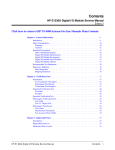
Contents
1 Introduction
1
2
3
IEEE 488 General Purpose Interface Bus
2.1
History of IEEE 488 Standard . . . . . . . . . . . . . . . . . . . . . . . .
3
2.2
Type of IEEE 488 Cards Available . . . . . . . . . . . . . . . . . . . . . .
4
2.3
IEEE 488 Connector and Wire Configuration . . . . . . . . . . . . . . . .
5
2.4
3
3.2
5
Data Bus . . . . . . . . . . . . . . . . . . . . . . . . . . . . . . . .
6
2.3.2
Transfer Bus . . . . . . . . . . . . . . . . . . . . . . . . . . . . . . .
6
2.3.3
Management Bus . . . . . . . . . . . . . . . . . . . . . . . . . . . .
7
IEEE 488 Connection Details . . . . . . . . . . . . . . . . . . . . . . . . .
7
Application Programmers Interface Libraries
3.1
4
2.3.1
11
Standard Instrument Control Library . . . . . . . . . . . . . . . . . . . . .
11
3.1.1
SICL Commands . . . . . . . . . . . . . . . . . . . . . . . . . . . .
12
Virtual Instrument Standard Architecture . . . . . . . . . . . . . . . . . .
14
Remote Access Implementation Method
17
4.1
Project Background . . . . . . . . . . . . . . . . . . . . . . . . . . . . . . .
17
4.2
Project Implementation Outline . . . . . . . . . . . . . . . . . . . . . . . .
18
Writing C Programs
5.1
21
Data Types and Structures . . . . . . . . . . . . . . . . . . . . . . . . . .
5.1.1
Basic Data Types . . . . . . . . . . . . . . . . . . . . . . . . . . . .
vii
22
22
7
8
9
Data Arrays . . . . . . . . . . . . . . . . . . . . . . . . . . . . . . .
25
5.1.3
Structures . . . . . . . . . . . . . . . . . . . . . . . . . . . . . . . .
26
5.2
Variable Scope
. . . . . . . . . . . . . . . . . . . . . . . . . . . . . . . . .
27
5.3
Input/Output in C . . . . . . . . . . . . . . . . . . . . . . . . . . . . . . .
28
5.3.1
Standard I/O with keyboard and monitor . . . . . . . . . . . . . .
28
5.3.2
Using files for I/O
. . . . . . . . . . . . . . . . . . . . . . . . . . .
30
Functions . . . . . . . . . . . . . . . . . . . . . . . . . . . . . . . . . . . .
31
5.4
6
5.1.2
Common Gateway Interface
33
6.1
HTML CGI Program Calling Method . . . . . . . . . . . . . . . . . . . .
34
6.2
CGI Program Basic Structure . . . . . . . . . . . . . . . . . . . . . . . . .
34
6.2.1
Obtaining Input . . . . . . . . . . . . . . . . . . . . . . . . . . . . .
35
6.2.2
Processing Data . . . . . . . . . . . . . . . . . . . . . . . . . . . . .
36
6.2.3
Output from CGI Application . . . . . . . . . . . . . . . . . . . .
37
Writing CGI Programs for Devices
39
7.1
Step 1: Open a Session with the Device . . . . . . . . . . . . . . . . . . . .
39
7.2
Step 2: Getting Data from Input String . . . . . . . . . . . . . . . . . . . .
40
7.3
Step 3: Obtain Device Commands . . . . . . . . . . . . . . . . . . . . . . .
40
7.4
Step 4: Changing Settings on the Device . . . . . . . . . . . . . . . . . . .
42
7.5
Step 5: Error Detection . . . . . . . . . . . . . . . . . . . . . . . . . . . . .
42
7.6
Step 6: Output Results . . . . . . . . . . . . . . . . . . . . . . . . . . . . .
42
7.7
Compiling Device Programs . . . . . . . . . . . . . . . . . . . . . . . . . .
43
Creating Web Pages for Remote Access
45
8.1
HTML Basics . . . . . . . . . . . . . . . . . . . . . . . . . . . . . . . . . .
45
8.2
Frames . . . . . . . . . . . . . . . . . . . . . . . . . . . . . . . . . . . . . .
49
8.3
Creating HTML pages for ATE Instruments . . . . . . . . . . . . . . . . .
52
Setting Up an Apache Web Server
9.1
Installing Apache . . . . . . . . . . . . . . . . . . . . . . . . . . . . . . . .
viii
55
56
9.2
General Configuration . . . . . . . . . . . . . . . . . . . . . . . . . . . . .
58
9.3
Configuring Server . . . . . . . . . . . . . . . . . . . . . . . . . . . . . . .
59
9.3.1
Controlling Access . . . . . . . . . . . . . . . . . . . . . . . . . . .
59
Adding Web Pages and CGI Programs . . . . . . . . . . . . . . . . . . . .
61
9.4
10 System Test
63
11 Conclusion
65
11.1 Suggested Further Development . . . . . . . . . . . . . . . . . . . . . . . .
65
A Project Specification
69
B ASCII Character Set
71
C GPIB Interface Cards
73
D HTML Pages
85
D.1 Function Generator . . . . . . . . . . . . . . . . . . . . . . . . . . . . . . .
85
D.2 Switch Unit . . . . . . . . . . . . . . . . . . . . . . . . . . . . . . . . . . .
86
D.3 Power Supply . . . . . . . . . . . . . . . . . . . . . . . . . . . . . . . . . .
87
D.4 Oscilloscope . . . . . . . . . . . . . . . . . . . . . . . . . . . . . . . . . . .
88
E CGI Applications
91
E.1 Basic CGI Applications . . . . . . . . . . . . . . . . . . . . . . . . . . . . .
91
E.1.1 CGI get Method . . . . . . . . . . . . . . . . . . . . . . . . . . . .
91
E.1.2 CGI post Method . . . . . . . . . . . . . . . . . . . . . . . . . . . .
97
E.2 CGI Programs for Devices . . . . . . . . . . . . . . . . . . . . . . . . . . . 100
E.2.1 Function Generator . . . . . . . . . . . . . . . . . . . . . . . . . . . 100
E.2.2 Oscilloscope . . . . . . . . . . . . . . . . . . . . . . . . . . . . . . . 107
E.2.3 Switch Unit . . . . . . . . . . . . . . . . . . . . . . . . . . . . . . . 113
E.2.4 Power Supply . . . . . . . . . . . . . . . . . . . . . . . . . . . . . . 121
F Basic C Programs
127
ix
F.1 Data Types . . . . . . . . . . . . . . . . . . . . . . . . . . . . . . . . . . . 127
F.2 Structures . . . . . . . . . . . . . . . . . . . . . . . . . . . . . . . . . . . . 128
F.3 Variable Scope
. . . . . . . . . . . . . . . . . . . . . . . . . . . . . . . . . 129
F.4 Input/Output Example . . . . . . . . . . . . . . . . . . . . . . . . . . . . . 129
G Application Interface Library
131
G.1 VISA Library . . . . . . . . . . . . . . . . . . . . . . . . . . . . . . . . . . 131
G.2 SICL Library . . . . . . . . . . . . . . . . . . . . . . . . . . . . . . . . . . 255
H Device Manuals
345
H.1 Function Generator . . . . . . . . . . . . . . . . . . . . . . . . . . . . . . . 345
H.1.1 Quick Reference . . . . . . . . . . . . . . . . . . . . . . . . . . . . . 345
H.2 Oscilloscope . . . . . . . . . . . . . . . . . . . . . . . . . . . . . . . . . . . 356
H.3 MUX . . . . . . . . . . . . . . . . . . . . . . . . . . . . . . . . . . . . . . . 413
H.4 Power Supply . . . . . . . . . . . . . . . . . . . . . . . . . . . . . . . . . . 434
x
Chapter 1
Introduction
The objective of this project was to develop a method of providing remote access between
a users computer and the devices in the Automated Test Equipment rack. This access
method was to be in a manner that overcomes some of the problems with the system
that was investigated previously. In completing this project the following steps had to be
achieved:
1. Interface card had to be identified
2. Application Programmers Interface Libraries had to be obtained
3. Device command had to be Identified
4. Programs that Interface with device had to be written
5. Web pages for interaction with devices had to be written
6. Web server had to be installed and configured
At the moment there is no system that provides remote access to the Automated Test
Equipment, this is due to limitations enforced by the Information Technology Services
department of the University. The previous system never evolved further then the setup
phase before these limitations where put in place for security reasons. The software that
was going to be used was Hewlett Packard Virtual Engineering Environment Version 5
and was the predecessor of the software being used on the PC connected to the Test
equipment. Version 5 provided remote access, but was hard to configure and required
software ports left open (listening) that are not used by the standard applications
permitted by firewalls.
1
Along with the inherited security problems that the software processed, the Windows 95 Operating system on which the software ran also created a security threat to the
whole University network. And to compound the already large deficiencies of the system,
it’s performance was troublesome and unpredictable. Hence a need for a method that
would remove the security problems and hopefully improve the reliability and performance
is the foundation of this project.
The major proportion of this project is the software generated to provide the remote access. The complete code for this project is contained on the CD-ROM attached to
the back of the thesis. This CD is broken it to the various stages required to implement
the remote access that was produced by the project. The directories and the files that
they contain are :
1. Libraries : Contains the API library files need to write a program.
2. Manuals : Contains the various device manuals that contain the commands for each
device.
3. HTML files : Contains the Web pages need to interface with the devices.
4. C files : Contains the cgi programs source files that interface with the devices.
5. Apache : Contains the installation executable for the Apache Web Server.
2
Chapter 2
IEEE 488 General Purpose Interface
Bus
The concept of using Automated Test Equipment for automation of test that are mundane
and prone to user errors is becoming more of an widely used technique. The ability to
write a program for a test sequence is becoming more attractive, as programs that provide
a graphical user interfaces become available. These software packages allow the user to
interact with the ATE systems via an interface card, without having to worry about the
underlying system. The interface protocol that most ATE systems uses is known as the
IEEE 488 standard, and has become a solid foundation for future ATE equipment to build
on.
2.1
History of IEEE 488 Standard
The IEEE 488 standard was original started in the late 1960’s as the Hewlett Packard
Interface Bus(HPIB), this was the protocol that Hewlett Packard originally devised
to connect and control devices that they manufactured. With the introduction of
programmable devices the need arose for the introduction of a standard by which devices
from different manufactures could interfaced was required.
In 1975 the Institute of Electrical and Electronic Engineers (IEEE) published the
IEEE 488 standard that detailed the electrical, mechanical and functional specifications
of the interface bus. This interface bus was specifically designed for the interaction with
programmable instrumentation and was reviewed in 1978 but no major changes where
made to the standard. This standard is now in world wide use by the major programmable
instrumentation manufactures and known by three different names:
3
1. Hewlett Packard Interface Bus (HPIB)
2. General Purpose Interface Bus (GPIB)
3. IEEE 488 Bus.
Work on standard continued as the original standard did not outline the syntax and
formating conventions for the communications with devices. Finally the new standard was
completed and released as the IEEE 488.2, with the original standard being dubbed IEEE
488.1. This standard contained information on Codes, Formats, Protocols, and Common
Commands for use with the IEEE 488 standard. The new standard did not replace the
original, with most new devices supporting both, instead it provides a reasonable level of
compatibility.
Finally in 1990 the IEEE 488 standard was appended to include the Standard
Commands for Programmable Instrumentation (SCPI) documents.
The Standard
Commands for Programmable Instrumentation is the most recent attempt to provide
compatibility between Programmable Instrumentation from different manufactures, this
is topic of [15] . This standard defines specific commands that each instrument class must
obey, if followed this will provide complete compatible and configurable systems among
these instruments.
2.2
Type of IEEE 488 Cards Available
Currently on the market there are many manufactures that are producing IEEE 488.1
and 488.2 cards for interfacing with programmable instruments.Some of the major
manufactures being National Instruments and Agilent Technologies Inc. Each of which are
compatible with the different instrument manufactures due to the standards specifications
and each with their own system drivers and API libraries.
Currently there are a few different interconnection methods between the interface
card and programmable Instrument. The main ones being the CN24 connector and cable
that uses a 24 pin connector and cable with 24 wires, the RS232 and Universal Serial
Bus(USB). The Last two connection methods are not commonly used as they are serial
connections, and the ASCII characters used by the IEEE 488 standard is more suited for a
Parallel transfer media such as the first method. Appendix C contains the various GPIB interface card produced by Industrial Automation Products and the card used in this project.
4
The speeds that the serial communication can obtain is less then that of the parallel systems, this is due to the fact that they can only send 1 bit at a time. But
the distances that a serial communication link can send is usually larger and the error
recovery is easier as the use of a parity bit is often sufficient to correct errors. In parallel
communication if an error occurs then more then one bit may be corrupted and retransmit
is required. The type of communication link required depends on environment under
which the equipment will be used, but the advantages of the 24 wire connection make it
the dominant method used.
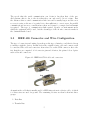
2.3
IEEE 488 Connector and Wire Configuration
The type of connectors and wiring depends upon the type of interface card that is chosen
to interface with the devices. In this section the original 24 wire cable and connector will
be considered.The cable and connectors often refereed to as the CN24 connector due to the
fact that they are comprised of 24 connector pins and 24 wires, the picture below depicts
such cables and connectors:
Figure 2.1: IEEE 488 CN24 cable and connectors
As mention the cable that is usually used for GPIB interactions is a 24 wire cable, of which
8 of these wires are used for ground. The remaining 16 wires are then broken into three
groups:
1. Data Bus
2. Transfer Bus
5
3. Management Bus
2.3.1
Data Bus
The data bus occupies 8 of the 16 signal wires, this is due to the fact that most of the
devices use the ASCII character set for there interactions. The ASCII character set only
requires a 7-bit number, but most computer systems use 8-bits(1 byte). The advantages
of using the ASCII character is that the commands can be recognizable to humans and
the data can be manipulated quite easily in programming languages. The data bus is
used to transfer data, control information and address.
An example of how the devices use this is shown using the APPL: command used
by the Function Generator, It contains 5 ASCII characters that can be sent via the data
bus one at a time in binary. So the decimal equivalent of how this command would be
sent is 65,80,80,76 and 58. The devices store the characters in a buffer then apply the
command, assuming the command is a valid one.
2.3.2
Transfer Bus
The transfer bus provides a handshaking protocol that allows the system to communicate
Asynchronously. It does so by allocating each of it’s three wire a specific meaning, such as
Not Ready for Data, Not Data Accepted and Data Available. Through the use of these
control line the system can communication without conflicts and the state of the device
can easily be obtain by checking the signals on these wires.
When a device wishes to transmit data on the bus, it sets the DAV line high
(data not valid), and checks to see that the NRFD and NDAC lines are both low, and
then it puts the data on the data lines. When all the devices that can receive the data
are ready, each releases its NRFD (not ready for data) line. Then when the last receiver
releases NRFD, and it goes high, the interface takes DAV low indicating that valid data
is now on the bus. In response each receiver takes NRFD low again to indicate it is busy
and releases NDAC (not data accepted) when it has received the data. When the last
receiver has accepted the data, NDAC will go high and the device can set DAV high again
to transmit the next byte of data.
This form of handshaking communication allows the devices to transmit at their
own pace and provides error detection through the use if the NDAC(not data accepted)
line. If any device fails to perform it’s part of the handshaking and releases NRFD or
NDAC lines then data cannot be sent, this will eventually result in a timeout error.
6
2.3.3
Management Bus
There are 5 wire allocated to manage the flow of data bytes across the interface and
control amongst the various devices connected on the one bus.
The ATN (Attention) signal is asserted by the Interface Card to indicate that it
is placing an address or control byte on the data bus. ATN is released to allow the
assigned device to place status or data on the data bus. The interface card regains control
by reasserting ATN, this is normally done synchronously with the handshake to avoid
confusion between control and data bytes.
The EOI (End or Identify) signal has two uses. A device may apply a signal on
the EOI line simultaneously with the last byte of data to signal the end-of-data. The
interface card can assert EOI along with ATN to initiate a parallel poll. Although
many devices do not use parallel poll, all devices should use EOI to end transfers (many
currently available devices do not).
The IFC (Interface Clear) signal is set high only by the System Controller in order to initialize all device interfaces to a known state. After releasing IFC, the System
Controller is the Active Controller.
The REN (Remote Enable) signal is asserted only by the System Controller. Its
assertion does not place devices into remote control mode; REN only enables a
device to go into remote mode when addressed to listen. When in remote mode, a
device will ignore its local front panel controls until the local button is press on that device.
The SRQ (Service Request) line is like an interrupt: it may be asserted by any
device to request the interface card to take some action. The interface card must
determine which device is signaling SRQ by conducting a serial poll. The requesting
device releases SRQ when it is polled.
2.4
IEEE 488 Connection Details
Through the use of the Transfer and Management Bus the IEEE 488 standard is able to
have up to 15 devices connected simultaneously, with each device being assigned a unique
Primary address ranging from 0-30. This is similar to the way that Ethernet works,
the data is broadcast to all devices and the device uses the addressing information to
determine if the data was intended for them. A secondary address may also be assigned
to each device, also ranging from 0 to 30, but this address is optional and is usually not
7
assigned.
The cables that link the devices is a shielded 24-wire cable, and the distances allowed by the standard is either 20 meters or 2 times the number of instrument connected
to the bus, whichever is smaller. The speeds that are achieved by the GPIB standard are
in the range of 250 Kbytes/sec to 1MBytes/sec, note it is in Bytes/sec due to the fact
that the 8 data bus line. When considering the operating speed of the interface bus the
cable size must be taken into consideration, if high speeds are desired the the length on
cables used to connect the devices and interface card must be small.
The pin allocation is depicted in the following diagram:
Figure 2.2: IEEE 488 CN24 Connector Pin Configuration
From the diagram and Green[5] it can be seen that the 16 signal wires are broken down as
follows :
Data Bus:
Data bus
}
REN
EOI
Remote Enable
End or Identify
}
}
}
ATN
Attention
#
DI01 - DI08
Management Bus:
8
Ten
Synchronous
Signals
IFC
SRQ
Interface Clear
Service Request
#
# Six
Transfer Bus
NRFD
NDAC
DAV
Asynchronous
Not Ready For Data
Not Data Accept
Data Available
# Signals
# Twisted Pairs
#
This shows how the IEEE 488 standard handles the transfer of both synchronous and
asynchronous data.
9
10
Chapter 3
Application Programmers Interface
Libraries
An Application Program Interface as defined by (www.whatis.com,2004) is the specific
method prescribed by a computer operating system or by an application program by
which a programmer writing an application program can make requests of the operating
system or another application. In the case of this project the desired API is for the GPIB
card, so that programs can be written to interface with the programmable instruments
via the GPIB interface card.
After some researching on the topic of an API for the GPIB interface card contained in the system that the remote access is to be implemented, the manufactures of
the card Agilent Technologies Inc provide the API for download as part of a drivers
suit. Contained with the drivers which are necessary for correct operation of the card,
are two API’s. Which where the Standard Instrument Control Libraries and the Virtual
Instrument Standard Architecture, and these will be discussed further in the following
sections.
3.1
Standard Instrument Control Library
The Standard Instrument Control Library is a modular instrument communications
library that works with a variety of computer architectures, I/O interfaces and operating
systems according to [14]. This Library allows programs to be written in C/C++ or
Visual Basic that can interface with a GPIB card. One of the advantages as stated in [14]
is that programs written using this library can be ported at the source code level from
one system to another without, or with very few changes.
11
One down fall of the SICL library is that they are Hewlett Packard dependent,
meaning that they can only be used in conjunction with Hewlett Packard hardware.
Although it is limiting, the advantage is that the library is efficient,reliable and easy
to use with HP hardware. Also the library can be used to communicate over the
different interface methods used for programmable instrument communications such as
HPIB,GPIB,RS-232 and USB. This library contains a 32-bit and a 16-bit version for
windows, which is an advantage as the system connected to the ATE rack is running the
c
Windows95
operating system which is a 16-bit OS. The SICL library was the only one
that worked on the equipment in question for this project, so all programs written will
use this library.
3.1.1
SICL Commands
The reader is referred to [14] for a more detailed explanation of the commands and
specifics of developing applications using the SICL library, But a brief overview of some
of the important aspect of the library will be discussed in the following sections. The
concepts discussed in this section are Instrument independent and will be used for the
development on CGI programs in a later section. There are a few example programs
within [14] so these programs will be referred to rather than new example.
The first thing that an application has to do before it can interface with a device,
is create what is known as a device session which creates an ID by which the application
can identify the device it is talking too. As mentioned in the IEEE 488 standard each
device is given a unique address(see Table 7.1), this address in what is used by the SICL
library when communicating with a device. Also when the drivers for the GPIB card are
setup, the interface card is given a unique name so that more one interface card can be in
the one system at a time, each can be identified by it unique name. The way a session is
open is similar to the way that C opens a file and is displayed by the following code:
id = iopen(”hpib7,9”)
From the line of code above it can be seen that the iopen function is used open a
session with a device. It only requires the one argument which is a string that identifies
the interface card hpib7 and the address of the device on that interface 9. If the
function is successful then a variable of type INST will be returned and stored in the
id variable and will return 0 if it fails, INST is a user defined data type that is de12
fined by the library. This id will be used by the functions that read and write to the devices.
After a session is created then the iprintf and ipromptf functions can be used to
communicate with the device. The strings that these functions use are ASCII characters,
and are dependent on the device with which the interaction are with. The use of these
two functions are :
iprintf( id,”APPL:%s:%s\n”,wave type,VtoV Peek)
iscanf(id,”%t”,buff )
iprompt( id,”*IDN?\n”,”%t”,buff)
The iprintf function can be used with two or three arguments, and follows a similar format to the fprintf function for C. The first argument is compulsory as it contains
the device’s identity that is used in the communication. The second argument is the
string that is sent to the device, this string can be a constant string or composed of string
variable as long as it follows the format that the device expects. If the second argument
contains variable then a third argument must be used and is the list of variable names
that correspond to the format identifiers contained in the string.
The iscanf function is the similar to the C scanf function, except for the addition
of the session identifier. The function will read the data on the GPIB and will store it in
the variable passed to it, the %t format string specifies that an ASCII string will be read
back. The iprompt function prompts the device with the string specified and then stores
the response from the device in the variable in the fourth argument. The same sequence
of events could be achieved by using the iprintf followed by a iscanf, but this function
makes the process neat with only one line required.
Finally after all interactions with the device have been completed then the device
session must be close, just like a file in C. This is done using the iclose method passing
the session id as it’s argument like follows:
iclose( id)
For the purpose of assisting in the writing of reliable code the library provides
two functions to add in error detection and correction. The first of which is ioerror which
installs a default error handling routine which is called if any of the SICL functions result
in an error. The second of which is itimeout which allows the programmer to specify a
time(in milliseconds) that SICL will wait for a response from a device. When incorporated
into applications the programmer can detect errors and take action to minimize or fix
13
such errors.
3.2
Virtual Instrument Standard Architecture
The VISA library is similar to SICL, except they where developed with compatibility in
mind, allowing the library to be used on any manufactures hardware. Agilent Virtual
Instrument Software Architecture (VISA) is an IO library designed according to the
VXIplug&play System Alliance that allows software developed from different vendors to
run on the same system as stated in [19].
As with SICL, the VISA must create a device session before any communications
between the interface card and programmable instrument can take place. The way that
this is done is different then the SICL as two commands are need to create a session.
These commands are :
viOpenDefaultRM(&defaultRM);
viOpen(defaultRM, ”GPIB0::22::INSTR”,VI NULL,VI NULL,&vi);
With the VISA driver a session with the default resource manager must be created before a session with a device. This is due to the fact that VISA is an object-oriented
system and the word ’resource’ more specifically refers to a particular implementation
(or instance in object-oriented terms) of a Resource Class. The resource manager
is what maintains all of the class instances, so the class that is about to be create
must be registered with it. This class is then linked to the device, this section is
similar to SICL. The interface card is identity and the address of the device are
specified via a string. The next two arguments are VI NULL which means ”Do not
return the number of bytes transferred”, these are constants defined in the VISA
library which alter the operation of the VISA functions. Finally the last argument
is the address of a session variable and is exactly the same as the ID variable in the
SICL library, it is used by the I/O functions to determine what devices they are talking too.
The Input and output functions of the VISA library works exactly the same as in
SICL. These functions are viPrintf and viScanf and their arguments are exactly the same
as the previously explained iprintf and iscanf, each requiring a session id, a string and the
name of any variables that are being used in the string. The following shows their operation:
viPrintf(vi,”*IDN?\n”);
viScanf(vi, ”%t”, buf);
14
Closing the session after all the interactions have taken place is performed via the viClose
command with the session id being passed to it as it’s argument. The VISA library has
a large range of error detection functions and are explained in full in [19] and user are
referred to this manual if more information is desired.
15
16
Chapter 4
Remote Access Implementation
Method
With the advances in modern communication systems the potential to provide remote
access to application is becoming easier. The Internet has spawned an enormous following
and has become a multimedia base communications network. Due to the structure of
the Internet it is quite reliable and cheap and for these reasons has become an enormous
success. But because it is a shared media and the number of clients cannot always be
known, it’s performance cannot be measured exactly.
Taking into mind the Internet’s inherent advantages and disadvantages this is the
media that was in mind during the creation of this project. Nearly everyone can gain
access to the Internet from a vast number of locations around the world and due to it’s
shared nature the cost is relatively low, hence making it a perfect resource. However
the shared nature that makes the Internet so appealing causes a problem, security. This
problem has manifested itself recently as hackers write viruses, worms and Trojan horses
that gain access to systems thought to be secure, causing the need for protection.
4.1
Project Background
Some of the issues mentioned above are the exact reason that the previous attempts
to provide remote access to the ATE racks failed. The problem in this case was that
the software HP-VEE V5.0 that was being used to provide the remote access created a
security hole in the Universities firewall. The way that the software operated required
17
that a software port be left open so the server could listen on this port for any attempts
to connect. Hence for correct operation this required that the Firewall did not block this
port. As stated by [2] having any open ports exposes you to potential attacks that might
exploit known or yet-unknown vulnerabilities, this page also contains links to sites the
help identify open ports.
The vulnerabilities that [2] is talking about are those that exist either in the Operating system itself, or Trojan horses that have found their way onto the system. In
the case of the system that the HP-VEE software was installed on, the Windows
c 95
operating system is being used. This operating system was designed when networking
and the Internet where not very popular, so the concept of security was over looked or
undermined. So as well as the software leaving a port open, the OS on which it run could
also jeopardize the security of the whole university network.
With this in mind one way around the firewall would be to use an application
that uses a port that is allowed by the firewall. That is exactly why for this project the
web server based system was chosen as this application uses port 80 (HTTP) which is
allowed by nearly all firewalls. Also most web servers have the ability to specify the files
that can be access by a user and also can implement password access. The implementation
is similar to that used by most web pages that obtain data and process it in some manner,
such as a database searches that the google search engine performs.
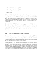
4.2
Project Implementation Outline
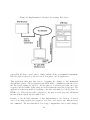
The concept of the way that the remote access will be implemented for the ATE rack, is
the Common Gate Way Interface Method which will be discussed in detail in chapter 6.
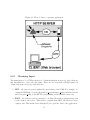
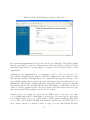
But for now the diagram below shows the basic configuration of this method:
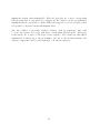
The diagram shows the communication paths between the different elements of this
implementation. At the centre of the system is the PC with a GPIB card, this system could
possibly contain multiple interface cards, and is a detrimental part of the implementation.
The PC is responsible for the communications between the user via the Internet and the
ATE rack via the GPIB card, and is responsible for controlling and monitoring the access
to the services that it provides.
The way that the PC performs these tasks is through an Apache Web Server that
is installed and configured to provide the services described previously. All configuration
changes can be done via configuration file and are discussed in chapter 9. The web server
allows the user to access web pages for interacting with the ATE systems, and these web
18
Figure 4.1: Implementation of Remote Access using Web Server
pages allow the user to enter data to change settings on the programmable instrument.
Once the data is retrieved by the web server, it is passed onto an application.
This application then uses this data to determine the changes to the Instrument
that the user desires. The program uses the SICL API to communicate with the device
and the desired setting are enforced. For the purpose of detecting problems, the device
is queried and the results of this query are check against the data sent by the user. The
application is then responsible for replying to the user, and must do so in the form of a
HTML code. This response will be displayed to the user as a web page and will inform
the user if their request was successful or not.
Because of the modular structure of this implementation, the division of devices
can be done using separate web pages for each device and even for the different device
sub commands. The way that this is done is up to implementor and is easily changed,
19
making the system easily maintainable. Each web page has one or more corresponding
CGI program that is responsible for carrying out the changes on the programmable
instrument that it corresponds to. If the ATE rack is upgrade or a device is replace, then
it is possible to alter the system with minimal effort.
Also the addition of providing advanced features, such as sequencing, this could
be done via separate web pages with their corresponding CGI program. Each page
would handle one or more of the steps for the sequence. The actual way that this is
implemented is entirely up to the programmer, and due to the modular structure, the
separate components could be used separately or in various sequences.
20
Chapter 5
Writing C Programs
The first and often most important decision when undertaking a software development
project is what programming language to use. Some of the criteria that must be
considered, as outline in [16], these are Readability, Writability, Reliability and Cost.
Each criteria must be considered in great detail as their weighting will vary for different projects, for example a real-time system will place greater importance in the reliability.
Also in conjunction with these criteria, other factors can greatly influence the decision of what programming language to use. In the case of this project, the availability of
the Application Programmers Interface for a programming language played a major roll.
The API for the GPIB interface card was only available for C/C++ and Visual Basic, so
a decision between the two had to be made.
Visual Basic is a simple programming language that allow the user to write programs quick and easily. But as with nearly everything this advantage comes with a cost,
visual basic programs can be unreliable and can be limiting in what features are provide
for the programmer to use.
The C/C++ programming language on the other hand is one with a much longer
history and although it is a high-level language, it also provides low-level features that the
programmer can implement into there code. C/C++ are languages that are very powerful
and provide the programmer with a large array of features, but can be dangerous if used
incorrectly by the programmer.
Although I have had experience with both of these languages, the C/C++ programming language is the one that was chosen for this project. This is due to the fact
that I have had more experience with the language and the programs compiled in C/C++
21
are more efficient (eg. Run faster, more reliable) than most other languages. In addition
the advantage of object-oriented programming provided by C++ allows for more efficient
code to be produced if desired.
The reader is referred to suitable introductory books if the fundamentals of C/C++
are not known. Suitable books include “Beginning with C” by Ron House [6] and
Object-Oriented Programming in C++ by Richard Johnsonbaugh and Martin Kalin [12],
however the some of the basics will be outlined in the following chapter.
5.1
Data Types and Structures
The most important structure in any programming language is the variables in which data
can be stored, manipulated and retrieved. The C/C++ language has a vast variety of data
types that the user can user and structures that allows the user to group variables that
logically belong in one structure.
5.1.1
Basic Data Types
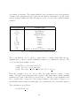
Within C there are a few data types and the user can define their own, each of which are
used to associate the data stored with it’s meaning and method of processing. A table
below shows the various data types, the amount of memory they occupy and the type of
data stored in them.
There are three basic data types:
1. char - ASCII characters.
2. int - Integer numbers.
3. float - Floating point numbers.
4. Pointers - Stores memory addresses.
The type of data that can be allocated to each variable is enforce by the compiler, so that
unintentional assignments don’t result data loss and hard to find bugs. The use can force
the allocation of a variable into a different type via type casting, this is done by placing a
(data type) in front of the variable to be converted.
22
For example :
int var = (int)float var;
This will cause the floating point variable to be converted to a integer variable and
assigned to int var.
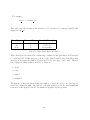
Data Types
char
int
float
Num. of Bytes
1
4
4
Variable Example
a,g,b,A,G
1,2,7,8,12
1.2,20.4,100.3
Table 5.1: Basic Data Types and Sizes
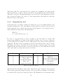
These data types can only hold a certain range of values, for integers this is -2,147,483,648
to +2,147,483,647. If this range is to short for the desired variable then a modifier, that
increases or decreases the number of bytes used by the data type, can be used. There is
four of these modifiers available in C/C++, these are :
1. short
2. long
3. signed
4. unsigned
The first two of these modifiers change the number of bytes allocated to the data type it
is used in conjunction with. The last two deal with weather or not the most significant
bit is used as the sign bit, if it is 1 the number is negative and 0 is positive.
23
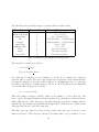
The following table shows the ranges of variables if the modifier is used :
Data Types
short int
unsigned short int
unsigned int
int
long int
signed char
unsigned char
float
double
long double
Num. of Bytes
2
2
4
4
4
1
1
4
8
16
Range
-32,768 to +32,768
0 to +65,535
0 to +4,294,967,295
-2,147,483,648 to +2,147,483,648
-2,147,483,648 to +2,147,483,648
-128 to +127
0 to +255
Increases accuracy
Increases accuracy
Increases accuracy
Table 5.2: Effects of modifiers and data type size
The way that a variable is as follows :
int variable name;
long int Variable Name;
Note that the C language is case sensitive, so in the above example two separated
variables will be created. The size of the variables are dependent on the system that the
programs is compiled on. Because of this a method of determining the size of a data type
is required, especially for dynamic memory allocation. In C the function sizeof(variable)
does exactly that, it’s usage is as follows:
size = sizeof(variable);
This will return an integer variable which is the number of bytes that the data
type occupies. By using this function then programs can be written to perform reliably no
matter what the size of the data types, especially when the program is obtaining memory
dynamically. An example program is shown in Appendix C, it shows how to define various
data types and the use of the sizeof function.
The final data type that C provide is the pointer, this data type is used to store
memory addresses. This data type allows C programs with a very powerful tool, as it
24
allows for functions to access variable outside their scope and the allocation on dynamic
variables. With the use of pointer the programmer is able to create abstract data types
that can grow in size dynamically, which useful when the number of elements is unknown.
The basic way to define a pointer is by putting a * character directly in front of
the variable name. The pointer can be of various data types so that the compile will
know how many bytes there are to each variable. This is required for features such as
the increment and decrement functions provided by C on pointers. The creation of a C
pointer is demonstrated in the following code:
int *int ptr;
int ptr = malloc(5*sizeof(int));
The first line of code creates a pointer to a int type variable, at this stage the
pointer is full of random garbage which happens to occupy the memory location assigned
to it by the compiler. The second line user the malloc function to create a block of
memory with 5 integer sized variables, note that the 5 could easily be a variable with any
value. If the malloc function is successful in the creation of this memory block then the
address of the first byte of the block is returned and entered into the int ptr variable,
however if malloc fails NULL is returned.
The most important thing to note here is that the variable int ptr contains the
address of the variable, hence to access the contents of the memory address the indirection
operator (*) must be used. This must be placed before the variable name, similar to the
way the pointer is created, then the pointer can be used just like a normal variable. This
property will be shown in the following example:
*int ptr = 4;
printf(”The pointer contains %d \”);
5.1.2
Data Arrays
The previous data types are only capable of holding one variable at a time. In most cases
such as a string of characters are need, especially when writing programs for the GPIB as
the commands to the devices are comprised of string of ASCII characters. So a way in
which logically grouped data can be stored is required.
25
The C/C++ languages provide the user with the ability to define an array of a
specific data type of any dimension. The way in which an array is created and indexed is
as follows :
char array[10];
int intarray[10][10];
array[0]= ’h’;
intarray[0][0] = 2;
With indexing an array in C the index range is from 0 to the size-1, so in the
example above the index is 0 to 9. The second line in the example shows how a multi
dimensional array is created, the indexing is the same as a single dimensional array except
an index for each dimension is required.
5.1.3
Structures
In most cases it is common that different data types are required to identify an object, for
example a student may have a Name, age, Student number and grade point average. So it
makes sense to group this type of data into one entity, this is the purpose of C structures
and C++ classes. The following code is an example of how a structure is created and
defined as a new data type in C is as follows:
typedef Struct Student {
int age,student number;
char name[30];
float GPA;
} STUDENT;
After the structure is defined using the typedef function then the user can create
a variable of this type in the same manner as a standard data structure. The label
assigned to the data types in the string after the right parentheses and before the semi
colon, in this case STUDENT. The creation of a student variable is as follows:
STUDENT St1;
26
After the variable has been created then each of it’s elements can be access using
the ’.’ operator. The following shows the student data type being used:
St1.age=18;
strcpy(St1,”Nathan”);
printf(”Age is %d \n”,St1.age);
A full example program of the use of structures is found in Appendix C.2 .
5.2
Variable Scope
One of the most important considerations whenever writing C programs is the scope of a
variable. The scope of a variable as defined by [16] is the range of statements in which the
variable is visible. If the scope of variables is not considered then this can lead to hard to
find bugs. A small sample program below displays variable scope:
/************************************************************
* File Name: scope.c
*
*
*
* Description: This program demonstrates the scope of *
*
variables in C
*
*
*
* Written By: Nathan Hetherington
*
************************************************************/
#include <stdio.h>
#include <stdlib.h>
#include <string.h>
1
2
3
4
5
6
7
8
9
10
11
12
int x;
13
14
// Defines sub routine
void sub1(void){
int x=50;
printf("x is %d in Sub1\n",x);
}
15
16
17
18
19
20
int main(void){
21
22
27
x=10;
printf("x is %d in the main function \n",x);
23
24
25
sub1();
26
27
printf("x is %d after sub1\n",x);
28
29
sleep(5000);
return 0;
30
31
}
32
33
34
The results from running this program after it is compiled results in the following output :
x is 10 in the main function
x is 50 in Sub1
x is 10 after Sub1
From examining the output the variable x defined before the main function is
seen through out the whole main function, the x variable defined in the Sub1 function is
only visible to the statements in sub1. If Sub1 was meant to change the x variable, then
this could lead to problems and in a program with more line could be difficult to find.
This shows that create care with respects to variable scope must be taken when writing C
programs.
5.3
Input/Output in C
The C programming language allows the user to read and write to what is referred to the
stdin(Standard Input) and stdout(Standard Output). This standard input and output is
by default the keyboard and monitor respectively, but C also allows the user to specify a
file or some other I/O device. The interfacing with I/O is done via functions provided by
the C standard libraries , such as stdio.h and stdlib.h, or API libraries for the I/O device
such as the sicl.h and visa.h libraries for this project.
5.3.1
Standard I/O with keyboard and monitor
There are a few functions provided by the standard C libraries that read from the
keyboard, their use depends on the type of data desired. Two such functions are scanf
and gets , the first obtains a single variable of the type specified and the second is used to
28
get a string of characters. The output is handle by the one function printf and prints the
contents of the variables passed to it, the way the variable is interpreted depends on the
variable format identifier used.The following is a table of some of the format identifiers
available:
Format Identifier
%d %i
%o
%x %X
%u
%c
%s
%f
%e %E
%g %G
%p
%n
Variable type
Decimal signed integer.
Octal integer.
Hex integer.
Unsigned integer.
Character.
String.
double.
double.
double.
pointer.
Number of characters written by this printf.
Table 5.3: Format Identifiers used with I/O functions
The printf function can be called to print either a constant string that the programmer hard codes in, a variable within the program or a combination of the two. The
code below shows an example of each :
printf(”This is a Constant String\n”);
printf(” %d %f \n”,int var,float var);
printf(” The integer variable has the value %d \n”,int var);
From the examples above we can see that the printf function requires 2 arguments. The first is the string that will be printed, this string must contain formating
identifiers and control characters (\n for new line ). And the second argument is the
list of variable that correspond to the format identifiers. Care must be taken to ensure that the variable names are in the right order, otherwise incorrect data will be printed.
The scanf function is as follows :
scanf(%d,&int var);
29
This shows that the scanf function also requires two arguments, the first tell the
function what type of data is expected and the second argument is the variable that the
data will be stored in. The important thing to note is the use of the ampersand operator,
this operator in C means ”the address of”, and is important for the function to know the
memory address of the variable.
5.3.2
Using files for I/O
C allows the user to use files for input and output and does so in a similar manner to the
standard I/O functions. The only difference is that an ID for the file is needed, and is
created using the fopen() method and after used the file must be closed using the fclose().
These functions are used in the following manner:
FILE *id;
id = fopen(”Filename.txt”,’r’)
In order to read and write to files a pointer to the file must be created, this
pointer is type FILE and is defined in the stdlib.h C library. Once a pointer of this type
is created then the fopen method is used to link the file to the pointer, and it requires two
arguments. The first of these arguments are the file name that is in the form of a string,
this string can be hard coded in of enter by the user into a character array. The second
argument is the mode the file will be opened in, and there are a few different modes that
can be used when accessing a file, they are as follows:
Format Identifier
a
a+
r
r+
w
w+
Variable type
Appending .
Reading and appending.
Read only.
Reading and writing.
Write only.
Reading and writing.
File Created?
Yes
Yes
No
No
Yes
Yes
If File Exists?
Append to
Append to
If not found returns NULL
If not found returns NULL
Overwritten
Overwritten
Table 5.4: fopen File modes
After the file has been linked to the pointer, then the file can be written to and read from.
These task are performed using the fprintf() and fscanf, which are similar to the function
for standard I/O except they require file pointer. The Examples below demonstrate this:
30
fprintf( ID, ”Number %d:\t %d\n”, i+1, score[i] );
fscanf( fp, ”%d”, &i);
From the examples above it can be seen that their use is exactly the same as to
standard I/O, except for the addition of the file pointer. All format identifiers and control
sequences are exactly the same.
5.4
Functions
Within C this allow the user to write functions that perform some task and can be called
by the user in a similar manner to those defined by the C libraries. The advantage of this
is that the user can write a function that performs a certain task, and call it when desired
instead of replicating the code each time the task is needed. The following code defines
a function that multiples two numbers, of course a function may do more complex thing
then this :
int mult(int x,int y){
int z=0;
z = x*y;
return z;
}
From this we can see the basic structure of the a C function. This first important value is the return type of the function, this tell what data type will be returned
from the function. The next is the name of the function, and can be any name as long as
it does not contain any of C’s special characters. Finally the last element of a function
is the arguments, this is the data that is passed to the function for processing. There
is no real limits on the number of arguments that a function can have, but is up to the
programmer to limit this to a reasonable amount.
The main function is a special case of a function, but the same rules exist. Finally if no return type or arguments are needed then the void data type can be used. And
the user is referred to Appendix C for sample programs.
31
32
Chapter 6
Common Gateway Interface
The Common Gateway Interface as defined by [3] is a standard for interfacing external
applications with information servers, such as HTTP or Web servers. This allows the
user to pass information that can be processed by the application to achieve some goal,
this type of interface is used for a large variety of tasks. These task range from simple
applications that query a database or process order information for On-line shopping, to
more complex applications that control equipment such a space telescope or programmable
electronic test equipment, the reason for this project.
When using the Common Gateway Interface, the web server allows the user to
run the application locally on the server. This is the most important point, the application
is not run on the user’s system, it is run on the system that the web server is installed on.
So because of this fact the programmer must take some precautions writing CGI programs
to ensure the security of the system is preserved. As outlined in [3] this security is usually
controlled by the administrator of the web server, and is performed by controlling the
directories that the user can access. The CGI applications reside in their own directory,
this informs the web server to execute these file rather that display them on the browser.
To ensure a more efficient and compatible system, CGI programs can be written
in a variety of programming languages. The most used languages for CGI programs are
C/C++, Perl and Unix Stripting Languages (BASH,KORN, etc.). If a language such as
C/C++ or Visual Basic are used, then the program must be compiled and the resulting
executable placed in the cgi bin directory of the web server. In the case of scripting
languages such as Perl which are interrupted languages rather then compiled, the script
can be placed directly into the cgi bin, and an interpretor will need to be installed and
functioning on the system. It is worth noting that the interpreted languages will be slower
than their compiled counterparts, so if efficiency is of importance then a language such of
33
C/C++ should be used.
6.1
HTML CGI Program Calling Method
The common way that CGI programs are integrated into web pages, is to have a button
that once click causes the application to be run. The HTML code that does this must
also specify the method which will be used for passing the information to the application.
The code below is responsible for this :
<FORM METHOD=”POST” ACTION=”/cgi-bin/cgipost.exe”>
... Code for data entry goes ...
<INPUT TYPE=”submit” VALUE=”Press to Submit”>
</FORM>
This input is pretty self explanatory, it consists of the method of input data and
the application to run when the submit button is pressed. The string in the action
section contains the path of the application, and is referenced from the web servers main
directory. There are no limitations on the number of forms displayed on the one web page,
so it is possible to have multiple submit buttons corresponding to separate applications.
Caution must be taken when using multiple forms to ensure the correct application is
called for each data set.
6.2
CGI Program Basic Structure
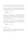
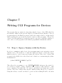
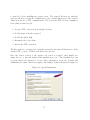
The basic operation of the CGI is shown in the following picture obtained form [4]:
From this figure, it can be see that is the Common Gateway interface is comprise of the
three components mentioned in Chapter 4. This section will deal with the creation of the
Gateway programs depicted in the diagram. All CGI applications will follow the same
basic structure, and are comprised of three sections. These are obtaining input from the
user, performing applications task and outputting a web page to user containing the status
of the application. The reader is referred to Appendix E.1 which contains CGI example
programs obtained from [13].
34
Figure 6.1: Flow of data to a gateway application
6.2.1
Obtaining Input
The main purpose of a CGI program is to obtain information from a web page, then use
this information to carry out some tasks. There are two way that a CGI program can
obtain data from a web page, and these are:
1. GET – the data are passed within the query string of the URL. For example, accessing the URL http://server.edu/stuff/cgi program?query string sends the data included in query string to the HTTP server running on the machine server.edu.
2. POST – the data are sent as a message body that follows the request message sent
by the client to the server. This is more complex than GET, but allows for more
complex data. This method uses Standard I/O to pass the data to the application.
35
Looking at the examples in Appendix E.1 it can be seen that the get method uses
environment variables to pass the data to the application. The application then reads the
environment variables by using the getenv() function. This function requires the name of
the environment variable to be obtained, and returns the contents of the contents of the
environment variable specified by the argument.
The environment variable that is on interest in the get method is QUERY STRING, this
is a string that contains all the information from the web page that the application is
to process. The format of this string is the same no matter weather the GET or POST
method is used, and is as follows:
TEXT LINE ONE=some+text&TEXT LINE TWO=default+value
&TEXT LINE THREE=1234&PASSWORD FIELD=secret
The sections in capital letters are the names of the input fields on the web page,
the field name and value are separated by the ’=’ character and any white space
is replaced by a ’+’ character. Each of the separate fields are separated using the &
character, so the application must use these special characters to filter out the desired data.
The post method is much simpler to use, as the data is read from the Standard
input. This is done using the following line :
bytesRead = read(STDIN, &readBuf[0], READ BUFLEN);
The function requires three arguments, then first specifies what input to read
from and in this case is STDIN, which is defined previously as 0. The second argument
is where the data read from the standard in is to be stored, the text in this argument
specifies the first byte of the buffer readBuf. The last argument tells the function the size
of the buffer, this is so it can keep track of how much more data can be placed in the
buffer.
6.2.2
Processing Data
As mentioned previously the data is sent to the application as one large string, this string
must first be processed and the different elements separated. After the string has been
processed and it’s elements are obtained and stored in different variable, then the application can use the data to perform any task desired. In the case of this project after the
data has been obtained then it can be used to change the settings on the Automated Test
Equipment.
36
6.2.3
Output from CGI Application
After the application is finished performing all the tasks it is required to, then it must
respond to the user with some feedback. This response must be in the from of a HTML
web page and must contain all the headers and trailers that a standard web page contains.
This can be seen in the examples in Appendix E.1.1, with lines 51 to 62 of cgiget.c
defining the HTML header and 262 to 264 adding the HTML trailer.
Any code can be entered between the header and trailer as long as the code follows the HTML format. The programmer can use any functions from the string.h library
to manipulate the strings that will be displayed on the web page, and all information will
be in the form of ASCII characters. Because the program is what is responsible for the
reply, then the information that is sent back can depend on the results of the processing,
making the application capable of dynamic web development. The sending of data back
to the user is performed using the printf() within C, which prints to the standard output.
37
38
Chapter 7
Writing CGI Programs for Devices
The programs that are written for interacting with the devices of the ATE, will follow
the structure outlined in the previous chapter on Common Gateway Interface. The cgi
program written for the Function generator will be the eample referred to in this chapter
while describing the process involved in the creation of these programs. The process
described for this application is exactly the same for each device, with little variation, so
can be used to create programs for the different programmable instruments available.
7.1
Step 1: Open a Session with the Device
In order to communicate with a device, the programmer must create an interface session
with the device. The method to do this was outlined in chapter 3, where the iopen()
function is used to open a session and requires the address of the device. In the CGI
program for the 33120A device, the address can be defined as a constant using the #define
mechanism in C.
#define DEVICE ADDRESS ”hpib7,10”
This allows the programmer to use DEVICE ADDRESS whenever the actual device address is required, during compilation this is replaced with ”hpib7,10”. This
is not compulsory, but makes the code easier to understand and change later. If the
address of the device changes then only the definition string will need to be updated.
Using this address, a session can then be opened and the resulting ID will be use when
39
communicating with the device. At the completion of the program this session must be
closed using the iclose function, failing to do so will cause later run programs to act
unpredictably.
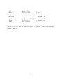
Device
33120A Function Generator
54602B Oscilloscope
34970A Switch Unit
6624A Power Supply
Address
10
7
9
5
Table 7.1: Addresses of Devices in ATE Rack
7.2
Step 2: Getting Data from Input String
As mention previously the data that is enter into the fields of the web page are read
into the program as one string. So the application must separate the data from
this large string. The format convention of the input string is, a = is used to separate the data label and actual data and the & is used to separate the different data inputs.
So the programmer can simply step through the input string, looking for the ’=’
character. Once this character is located then all characters between it and the next &
character is the data wanted. In the CGI programs there is a function that takes the
input string as the input argument and steps through the array of characters, separating
the various data. The user is referred to the CGI program for the function generator,
the code for the function getVariables(char *Buffer). This function will change from
application to application, and it’s sequencing is dictated by the sequence on the data
fields on the corresponding web page.
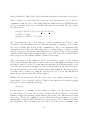
7.3
Step 3: Obtain Device Commands
The first step in the creation of the device command is to obtain the syntax of the
commands that will be sent to the device. The best source for such information is the
User’s Manual or Programmers Manual produced by the manufactures of the instrument.
For this project, these documents where obtained from the Agilent Technologies web site.
Once the device settings being changed have been determined, then the syntax of
the command to be sent to the device must be looked up in the manual. All commands
are hierarchal, this means that commands have subcommands that can be used in
40
conjunction, to specify the exact setting of the device to be changed. One example of
this is the APPLy command, that allows setting to be applied on the device, some of the
sub-commands are:
:SINusoid [<frequency> [,<amplitude> [,<offset>] ]]
:SQUare [<]frequency> [,<amplitude> [,<offset>] ]]
:TRIangle [<frequency> [,<amplitude> [,<offset>] ]]
:RAMP [<frequency> [,<amplitude> [,<offset>] ]]
:NOISe [<frequency—DEF> [,<amplitude> [,<offset>] ]]
:DC [<frequency—DEF> [,<amplitude—DEF> [,<offset>] ]]
:USER [<frequency> [,<amplitude> [, <offset>] ]]
From the above examples, the different are fields have the following meanings:
• Square brackets ( [ ] ) indicate optional keywords
or parameters.
• Braces ( { } ) enclose parameters within a command string.
Default parameters are shown in bold.
• Triangle brackets ( < > ) indicate that you must
substitute a value for the enclosed parameter.
So using the information contained above, a string can be generated to change setting can be generated. This string can then be sent to the device, and the desired
changes will be made. For example the following code will set the function generator to produce a sine wave with a frequency of 12Khz, 2V peak to Peak and an offset of 0V.
APPL:SIN 12Khz 2V 0V
Note that a semi-colon is used to separate the different command levels and there
is a space between the different input fields. When this string is sent to the device, a
newline character must also be sent to notify the device of the end of the command.
In the program written for function generator, the SIN section of this command string
depends on what is selected by the user.
41
7.4
Step 4: Changing Settings on the Device
Using the command created using the data obtained from the user and the commands for
the device, demonstrated in the previous step. The string can then be sent to the device
using the printf() function. This is done in the following way:
iprintf(id,”APPL:SIN %s,%s, %s\n”,Frequency,PtPVolts,Offset);
This is the line in the code that will actually implements the changes on the
device.
7.5
Step 5: Error Detection
After the string has been sent to the device, then it must be checked that the change was
actually implemented. The easiest way to check that the changes have been implemented
is to query the device for it’s current setting, this can then be compared to the string
that was sent to the device. The devices current settings can be obtained by using the
iprompt() function.
ipromptf(id, ”APPL?\n”, ”%t”, temp);
This will cause the current setting to be in the variable temp as a string, this can
then be compared using the string compare function strcmp(). If the two strings are the
same then strcpy will return 0, and then the appropriate action can be taken.
7.6
Step 6: Output Results
Depending on the result of the strcmp function, a result must be sent to the user to inform
on the status of their request. If the settings of the device where successfully changed, then
a web page stating that the settings have been applied will result. If the program fails, then
the user is informed to try again. There are nothing that the user can do if the problem
is with the hardware, in this case an error file is written and it is up the administrator to
check this file. Later implementations may sent an e-mail to the lab technician, informing
them that an error has occurred.
42
7.7
Compiling Device Programs
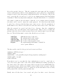
When compiling programs that make use of the SICL library, then some sets must be taken.
First is the inclusion of the sicl.h header file, which contains the prototype definitions of
the functions provided by the library. And finally, is informing the link which library file
contains the machine code for the functions defined in the header. In the case of this
project sicl32.lib was the appropriate file.
43
44
Chapter 8
Creating Web Pages for Remote
Access
The Hyper Text Mark-Up Language is a plain text based language, and can be created,
edited or viewed using a simple text editor on any computer platform. HTML is similar
to a scripting language as the web browsers reads the HTML file and determines the way
of formating the data from the code. This makes HTML multi-platform as long as a web
browser exist for that platform. Also with the modular structure of the web browser, this
allows for different services to be provided via plug-in. This makes the power of HTML
almost unlimited.
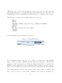
8.1
HTML Basics
The HTML language is based on what is known as HTML tags, these are used to
notify the browser of formatting method. The basic structure for all HTML tags are
<HTML TAG> to indicate the beginning of an HTML environment and </HTML TAG>
to finish the effect of this environment.
The first tag that must exist is the <HTML> tag as it tells the web browser
where the HTML code begins and ends. This alone would created a valid web page and
could be loaded, but the result would be a blank screen. After the beginning and end of
the HTML file is defined there are two more sections that need to be created.
The first of these sections is the HEAD, this section contains information about
the web page. One such element is the TITLE of the web page, the contents of
this field will appear in the browsers title bar. Additionally the contents of the
45
TITLE field will be used for the history list of the browser and also will be the title
entered when the page is book marked.The final section that a web page will consist of is
the BODY, this section contains all the information that is to be displayed on the web page.
The following code will produce a simple template for a web page:
<HTML>
<HEAD>
<CENTER><TITLE> Simple Web Page </TITLE></CENTER>
</HEAD>
<BODY>
<H1>This is a Simple Web Page !!</H1>
</BODY>
</HTML>
And the resulting web page from the code above is :
Figure 8.1: Simple HTML page
From the simple template, this code can be added to to make more complex HTML
pages. There are heaps of HTML tags that allow the developer to customize the
appearance of the web page they are developing. Typing text into the body section of the
HTML page will result in the text being displayed in the default font and size. But tags
must be used to format the appearance of the text,tables, division lines and other elements.
The HTML language provides the developer with a large range of features, just
like a word processor, to create format documents. The developer can insert pic46
tures,table, itemized lists and change the appearance of various elements of their page.
There are such a large number of element that can be changed through the use of HTML
tags, that readers are referred to introductory HTML books such as [1] or the Internet for
various formatting information.
Another important feature that HTML provide is the ability to create data entry
field, these are what will be used by this project to pass data to the CGI programs. There
a few different types of data entry fields, but the ones of interest for this project are, the
text entry field and radio buttons. The first element creates a box in which plain text can
enter, the maximum size of which can be set. The next has a grouped set of options, of
which only one can be selected at any time.
The tags just mentioned will be displayed by the following code and explained after the code:
<!−− This creates a comment >
<HTML>
<HEAD>
<TITLE> Customized Web Page </TITLE>
</HEAD>
<BODY BACKGROUND="background.jpg" TEXT="#FFFFFF">
<CENTER><H1>This is a Simple Web Page !!</H1></CENTER>
1
2
3
4
5
6
7
8
<P>This is an Itemized List:</P>
<HR>
<UL>
<LI>Item 1</LI>
<LI>Item 2<UL>
<LI>Item 2A</LI>
<LI>Item 2B</LI>
</UL></LI>
<LI>Item 3</LI>
<LI>Item 4</LI>
</UL>
<HR>
9
10
11
12
13
14
15
16
17
18
19
20
21
<P>Radio Buttons:</P>
<input type="radio" name="group1"
<input type="radio" name="group1"
<input type="radio" name="group1"
<input type="radio" name="group1"
22
value="Button1" checked> Button 1<br>
value="Button2"> Button 2<br>
value="Button3"> Button 3<br>
value="Button4"> Button 4<br>
23
24
25
26
27
<HR>
28
47
<TABLE align="center" border="3" width="668" cellpadding="3" id="table1">
<TR>
<TD width="222">Text 1 :
<input type="text" name="text1" size="20">
</TD>
<TD width="222">Text 2 :
<input type="text" name="text2" size="20">
</TD>
</TR>
</TABLE>
29
30
31
32
33
34
35
36
37
38
39
</BODY>
</HTML>
40
41
This code contain only a small proportion of some of the features provided by the HTML
language, but the use of options shown in the example demonstrates the convention
used for HTML options. Line 6 shows how options for the body section can be used to
alter the appearance of the overall page, the BACKGROUND option allow the background of the page to be set to a color or an image, the TEXT option defines the fonts color.
The use of the HR, P and BR tags show how they can be used to alter the appearance of the page. The P tag defines a paragraph, and creates the spacing before and
after the text that the code encloses. The BR tag creates a line break and does not require
a </BR> tag , this is the same as <HR> except a horizontal line is created across the page.
HTML provides the ability to create a list, the list will be numbered or have bullet points depending what tag encloses the list. In this case the UL tag is used and
produces a bullet pointed list, if OL was used then the list would be numbered. Each
element of the list enclosed within the list type are specified by the LI tag. The addition
of another list type can be used to create a sub list within another list.
The radio buttons can contain an unlimited amount of elements, but only one element can be selected at any time. The group is specified using the name field, all elements
with the same name will belong to a group. The value field is used to separate each of
the elements of a group, this is so that the individual button can be identified. One final
feature of the radio button is the ability to specify a default value, this is so that one of
the group is always selected, and is done using the checked option.
Finally is the text entry field, this element allows the user to under strings that
can be used by a CGI program. This element is created using the input tag, the type of
input is specified using the type field and the size option specifies the number of characters
that can fit in text field. Just like the radio buttons the text field has it’s own unique
48
name, specified in the name field. The way that the text fields are displayed in the above
example, uses a table structure which allows the creation of a matrix with the text fields
as the elements. This structure is simple to create, with the ¡TR¿ tag used to create a
matrix row and the TD tags create columns. This allow the developer to group similar
fields to create some logical grouping of data.
The figure below shows the page resulting from the code :
Figure 8.2: Web page with Background and other elements.
8.2
Frames
Also HTML allows the developer to create what are called frames, which allows multiple
Web Pages to be displayed at one time. Using this structure the developer can use one of
the HTML pages as a navigator to the other pages. This is the method used to provide
access the the different programmable instruments in the ATE rack. The following figure
displays the main page designed for this project, and the code after the figure shows how
a form is created:
49
Figure 8.3: HTML Frames
<html>
1
2
<head>
<!−− DOCTYPE HTML −−>
<!−− A Basic HTML Frames example −−>
<!−− Nathan Hetherington 2004 −−>
3
4
5
6
7
<title>ATE Remote Access</title>
8
9
<!−− this is for use by web search robots −−>
<!−− "keywords" is used for searching −−>
<!−− "description" is the summary returned −−>
10
11
12
13
<meta name="author" content="Nathan Hetheington">
<meta name="keywords" content="html">
50
14
15
<meta name="description" content="Provide remote access to ATE equiptment">
16
17
<!−−−−−−−−−−−−−−−−−−−−−−−−−−−−−−−−−−−−−−−−−−−−−−−−−−−−−−−−−−−−−−−>
<!−− 150 = pixels, * = remainder −−><!−− *** warning: if only a single panel *** −−>
19
<!−− do not use nested frameset environment −−>
20
<!−− 10%=percentage −−>
21
<!−−−−−−−−−−−−−−−−−−−−−−−−−−−−−−−−−−−−−−−−−−−−−−−−−−−−−−−−−−−−−−−>
<!−−−−−−−−−−−−−−−−−−−−−−−−−−−−−−−−−−−−−−−−−−−−−−−−−−−−−−−−−−−−−−−>
<!−−−−−−−−−−−−−−−−−−−−−−−−−−−−−−−−−−−−−−−−−−−−−−−−−−−−−−−−−−−−−−−>
25
</head>
26
27
<frameset cols="300,*" border="5">
<frame src="Frames_files/NavPanel.html" name="Nav">
<frameset rows="85%,15%">
<frame src="Frames_files/Project.html" name="Upper">
<frame src="Frames_files/Static.html" name="Lower" scrolling="no">
</frameset></frameset>
28
29
30
31
32
33
34
<noframes>
<BODY>
<P>
35
36
This document uses frames
This is in the noframes section
</p>
37
38
</body>
39
40
</noframes>
41
42
</html>
43
The code for this page was obtained from [13] and altered to suit need of this desired implementation. The important section of this code is lines 28-33, as this section is responsible
for the division of the page into frames. The frameset tag is used to specify the sections
containing the information about how the page is to divided, this division can be vertically
using the cols option or horizontally with the rows option. The size of the divisions are
specified with the option used, and can be expressed as number of pixels or as a percentage.
After the frame sizes have been specified, the pages that must be loaded into each
section must indicated. This is the purpose of lines 29,31 and 32 and various options can
be applied to each frame, such as the no scrolling option that is enabled for the static
frame. The division of the page and manner in which the pages operate is entirely up to
the developer, and allows for the implementation of more powerful, user friendly sites.
51
18
22
23
24
8.3
Creating HTML pages for ATE Instruments
The creation of HTML pages is a creative process, and aspects such as appearance and
operation can vary tremendously. But in the case of web pages for use with programmable
instruments, there are a few aspects of the implementation that remain constant. For
example the way that settings are changed is dependent on the way feature being set
operates, and usually varies from device to device. Some setting of a device may be
limited to a set of values, for example the wave type produced by the function generator,
so for this reason radio buttons more suit the acquisition of such information.
It is not totally necessary that the right input type be used, but it makes the development of CGI code easier. If a text box entry was used to acquire the wave type
desired, then the CGI application would have to check that the entered wave type is valid
and take action if it was not. With the use of the best suited input method, then the need
to code for error detection and correction is not necessary.
So for the implementation of web pages for the devices, a simple analysis of the
feature that the device provides was required. Features that only contain a discrete
number of setting are more suited for implementation using radio buttons, if a continuous
number of values where available then a text box should be used. The web page created
for interaction with the HP 33120A Function Generator is shown in the following figure:
The function generator’s web page above shows how multiple functionality can be
implemented on the one page. For this web page the selection of the waveform type is
done using radio buttons, this makes sense as there are only the four different waveforms
that the web page will provide. The selection of frequency, peak to peak voltage and
voltage offset is done using text boxes.
Creating web pages for each device allows the user to access and alter the settings
of the specific device that the page was written for. But the desire to provide some
form of sequencing to the user may be desired. This could be done by creating web
pages for each step in the sequence, then via a navigation frame such as the one used
for the main implementation above could be used to step through the steps. Providing
52
Figure 8.4: HP 33120A Function Generator Web Page
the sequencing in this manner would reduce the size an complexity of the CGI programs
that are responsible for each step. This structure would also make it possible to use the
individual components in a various number of sequences, and each step would be easily
maintainable.
Alternatively the implementation of sequencing could be done via the use of a
page with the individual steps all listed, with the submit button only available for the
step currently available. Through the use of a complex CGI program for each step, a web
page with the submit button for the next step being returned after the changes have been
implemented. This manner of implementing the sequencing has the advantage of stepping
the user through the step automatically, the main disadvantage of this method is the cgi
cannot be used for another sequence. If a new sequence was desired then a new web page
and corresponding CGI programs would need to be created.
Another aspect of creating web pages for the ATE devices, is the type and number of settings that should be implemented on each page. For some devices, such as the
Power Supply, using one page to contain all the possible settings is sufficient. But in the
case of other devices such as the Function Generator, Oscilloscope and MUX, there are
far too many options to be included on the one page. So some form dividing the these
53
setting must be decided.
As mention in chapter 7, the device settings are separated into sub command and
using these divisions would make sense. This type of devision would make the development of CGI programs that are responsible only for a certain sub-command, decreasing
their size and complexity. Also be cause the sub-division of command is done based on
the function they provide, this type of division is logical.
But there is no need to implement all the commands and sub commands, as a
majority of these features many not be need or could be out of the scope of the users
knowledge. So providing access to only a small group of commands is also possible, and
the commands omitted could be left as their default or set to a desire value. Creating the
web pages in this manner controls the type of settings that the user can use, and helps
in the coding of corresponding CGI programs. The code for the pages created for this
project are located in Appendix D, these page contain only basic features for each device.
The other features for the devices can be implemented in a similar manner.
54
Chapter 9
Setting Up an Apache Web Server
The web server used in the implementation of this system does not matter, as long as it is
capable of providing the Common Gateway Interface method. There are various reasons
for choosing Apache as a web server, for both this project and web hosting in general.
This first is Apache’s dominance in the web server domain, this is illustrated by the graph
shown in the figure below. The only other web server that has a noticeable following is
Microsoft’s Internet Information Server, which is shipped with Windows Server operating
systems.
In addition to it dominance of the market, Apache is also a cross-platform web server.
This means that versions of Apache can be obtained for various operating systems, such
as Microsoft Windows, Mac Os and Linux/Unix. From the view of this project this is
beneficial, as the system could be implemented in another Operating System, inheriting
their security and reliability advantages.
Probably the most appealing aspect of the Apache web server, is the amount of
On-Line documentation and support that is available. This is due to the fact that Apache
is an Open Source program, making it free to the public. And because this software is
open source, this means that any software bugs and security holes are often detected
and corrected much quicker then commercial products. Apache can be obtained from
www.apache.org and is free for download in various versions and platforms. This site
also contains a large amount of documentation for the installation and configuration of
the apache server.
For this project an older version of apache web server was required, this is due to
the fact that the system that apache was to be installed to contains the Windows 95
Operating System. Attempts to install new versions resulted in problems, mainly due to
55
Figure 9.1: Market Share of Various Web Servers
the fact that later versions are designed to take advantage of Thread technology. The
Windows 95 OS is not a true multi-tasking OS and does not support the use of threads.
Also it is worth noting that using Windows 95 for a web server is advised against, because
of the security risks that the OS creates. So for further development of the process
developed by this project, it is advised that a different OS is used for the system.
9.1
Installing Apache
As mentioned earlier, Apache can be downloaded from www.apache.org or various mirror
sites and can be obtained in binary or source form. If the source code version is acquired,
then it must be compiled prior to installation. The advantage of the source version is that
in the compilation process, it can be optimized for optimal performance on that system.
But a majority of the time the binary version is sufficient, and comes in .exe or .msi format.
There is not much difference between these two formats, except the msi files are
smaller. The msi windows installer technology contains all data and instructions required
to install the application on a system. In order to use a msi file then the msi.dll dynamic library must be installed, this is not necessary in later versions of Windows such as XP,2000.
For the Windows 95 operating system, the winsock libraries have to be updated
56
to winsock 2 before installing the apache server. The winsock libraries are what the
windows OS uses for network communication, and contains functions for the creation,
destruction and use of TCP communications. Web servers use TCP for their communications, which as stated in [18]:
1. Accept a TCP connection from client(a browser).
2. Get the name of the file requested.
3. Get the file (from disk).
4. Return the file to the client.
5. Release the TCP connection.
The file required to add support for msi files and update the winsock libraries are on the
attached CD, or can be obtained from Microsoft’s web site.
Once the desired version of the Apache web server is acquired, then simply executing the exe or msi will initiated the installation process. The installation process
is pretty much self automated, except where information about the Domain and
Administrators e-mail address are required. An example of this is shown in the figure 10.
Figure 9.2: Apache Installation
57
9.2
General Configuration
Most of the configuration settings that relate to the operation of the web server are done
via the httpd configuration file. This file is located in the confs directory, which is in the
directory that the server was installed to. This file is a text based file, that is read by the
server during loading.
An example of some of the configuration changes that are handled by this file, is
the location of the web pages and the cgi programs. This allows the user to specify any
directory that contains web pages that will be accessible for users. This configuration file
is divided into three sections :
1. Global Environment
2. ’Main’ server configuration
3. Virtual Hosts
The Global Environment allows settings such as the root directory where log file and
configuration files are located. Also certain aspects of the operation of the web server can
be changed via global environments, such as Timeout, Whether or not to allow persistent
connections and maximum number of requests a server process serves. Aspects such as
the number of request processed and the timeout are important for this project.
For the ATE remote access we want only one person changing the device settings
at a time, using this global variable is not a very effective method of providing mutual
exclusion. So for future implementation a better method of limiting access to one user
at a time would be needed. Also the timeout property of the server may need to be
changed, if the application applying the changes on the device takes to long the a time
out may result. This could mean that a timeout may result when there is no problems
on the server side, so increasing this timeout would help prevent this problem. But in
order to not have the user waiting too long, so an approximation of the longest command
processing time and a maximum round triptime for the request would need to be estimated.
The next section of the configuration file deals with the location of various files
need by the server, including the HTML page that the server will provide access to.
Along with this it also specifies the that access will be controlled, allowing or denying
based on user names and passwords or IP addresses. This is where security settings can
be enforced, through the selection of appropriate options.
58
Finally this last section allows the establishment of virtual hosts, which allows
multiple domain/hostnames to exist on the one server. This maybe desirable if the server
is to host web pages for different sites, such as a web hosting service would provide. In
the case of this project there is no need to have multiple domains or hostnames, so this
section will be left as is.
As mentioned earlier, there are many sources of apache web server configuration
on the Internet. Hence the user is advised to search on the Internet for help regarding to
the configuration of Apache Web Servers, if more detail is required. The site from which
the Apache server is obtained, www.apache.org is recommended as a good starting
point for such information.
9.3
Configuring Server
After the web server is installed, then all configurations are done via the httpd configuration file. This file is accessed and edited using a simple text editor, and contains code
that look similar to HTML code. This file is read by the server application upon starting
and specifies the operation of certain aspects of the server.
9.3.1
Controlling Access
For this project, there is the desire to provide a form of controlling access to this web site.
Through the use of the httpd configuration file ,files created by the administrator and a
file created by an application provide by the apache server, this facility can be provided.
The first stage in configuring controlled access is the creation of a password file,
this is done using a program that comes with the apache server called htpasswd. This
application is executed with three arguments, the first is the options that the user wishes
to enable, secondly is the file that will store the user/password information created and
last is the user that will be entered into the file. The basic operation of this application is
as follows:
htpasswd -c /usr/local/apache/passwd/passwords username
The user will be prompted to enter the password, this will cause the creation of a
59
file in the specified directory. This file contains the users name and the encrypted
version of the password, this is so later authentication can be achieved by comparing the
encrypted version of the enter password with that in the file. Note that the -c flag is only
use to create the file, if a user is to be added to an existing password file then this flag
is submitted. This is very important as using the -c flag will cause the file to be overwritten.
Care must be taken in the placement of this file, as it contains password information that could be used to guess the actual password. For this reason this should
be placed in a directory that the http server cannot access. Also the permissions of
the file must be set to allow access by the web server user, hence deny access to other users.
After the password in created and placed in a directory, then the configuration
files must be set to use this newly created password file. This is done by creating and
placing a file in the directory that is password protected, this file must be give the name
htaccess. The fields that must be entered into this file are now describe :
AuthType
AuthName
AuthUserFile
AuthGroupFile
Require
Authentication type being used.
The authentication realm or name.
The location of the password file.
The location of the group file, if any.
The requirement(s) which must be satisfied in
order to grant admission.
The htaccess file created for the project’s web server is as follows:
AuthName ”ATE User Login : ”
AuthType Basic
AuthUserFile ”c:/Program Files/Apache Group/Apache2/conf/htpasswd”
AuthGroupFile /dev/null
require valid-user
From this it can be seen that the basic authentication is used to control the access to the devices, this could be and of the various authentication setting depending on
the desired effect. The path to the password file is specified by the AuthUserFile line,
and was placed in the conf directory which is only accessible by the web server. And the
required field specifies that in order to be granted access the user must be have an entry
in the password file, and the passwords must exist.
Finally after all files have been created and placed in their correct directories,
60
then the httpd configuration file must be edited to inform the server to use password
access. This is done by editing AllowOverride option of the <Directory ”C:/Program
Files/Apache Group/Apache2/htdocs”> section, which specifies access to the web pages
in this directory. The AuthConfig option is used to activate the password access, after all
these steps are done then the web server must be restarted.
9.4
Adding Web Pages and CGI Programs
After the web server has been installed and configured as desired, then adding the contents
of the web page is simply a case of placing the files in the correct directory. In the case of
the html pages and cgi programs, this is the directory specified using the <Directory ...
>.
The defaults for these fields are the htdocs and cgi-bin directories located in the
directory where the web server was installed on the system. Once the files have been
placed in their correct directories, then any links or references to these files in the HTML
pages must be updated to reflect there current placement.
61
62
Chapter 10
System Test
The testing of this system was simply a matter of seeing weather it worked under certain
circumstances, as there are no real other measurable performance aspects. The system
must be test in a manner that would simulate it’s normal operation if implemented in the
real world. If operation under these circumstances then there is no reason why the system
would not operate correctly through the Internet.
The ideal way of testing this system, would be to provide the remote access system to be accessible via the Internet. But this was not possible, due to difficulties
imposed by the information technology services due the possible security faults. This is
understandable as the windows 95 has many security faults, and is not recommended as a
web server as specified by the apache web server developers.
So in order to test this system and eliminate any chances of compromising the
security of the Universities network, the different components that a majority of
the Internet used. The first element is over an ordinary Ethernet network, once
success has been proven on this configuration, a router will be implemented. The router
will allow the testing of how the system operates, when going from one network to another.
For the test of the system over an Ethernet, the PC’s where given IP addresses
192.168.0.1 and 192.168.0.2 respectively.The second address was assigned to the PC
running the remote access system created by this project. Gaining access to the system
from the second PC, was simple a matter of entering 192.168.0.2\frames.html into the
address bar of the web browser of the first PC.
Once performed the introduction web page loaded, and the function generators
page was chosen. Entering data into the fields and pressing the submit button resulted in
63
the desired changes on the instrument, then another device was chosen and also proved
successful. This means that the system operated successfully as predicted, under the first
test circumstances.
The next test required the configuration of a router, in this case a laptop with an
on-board network card and a PCMCIA network card. One of the Network Interface
Card(NIC) was given an address of 192.168.0.1 and the other 192.168.2.1, and an entry
was entered in the routing table of this PC so that information from one network to the
other was passed to the correct interface device. Two PC’s where connected to the laptop
through the use of two network hubs, and each PC assigned an IP address that was from
the same network of the NIC device of the laptop connected to the same hub. The system
was tested using the ping command, and it was found that each host was reachable
through the router.
Now the same test as previously used was duplicated, except the IP address was
192.168.0.2, and the PC being used was on a different network. The system was also
proven successful under these circumstances. There was no noticeable delay, due to the
router, but this was expected as on the Internet usually more than one router exists and
the networks are processing more of a load.
So from these test, it is expected that the system will operate correctly over the
Internet. Of course a much longer delay would be expected, but not enough to effect the
system’s performance. This is due to the fact that more routers would be traversed and
the propagation delays caused by the communication media, the usual round trip time is
around 200 ms. This would be noticeable, but the system only sends a small amount of
data and would not be expect to cause the system to fail.
64
Chapter 11
Conclusion
At the completion of the thesis the system provides a small amount of functionality for
each device, and web pages through which the interactions are performed. An Apache
web server that hosted these web pages and provided password controlled access, was
installed and configured. This was the major achievements of the project.
The web pages created to provide remote access to the devices could be used to
provide access to the ATE Rack for external students. This would benefit student that
would normally have to travel long distances to access these devices. Also assignments and
practical assessments could be created using web pages and CGI programs, for students
to complete remotely.
Also it is suggested that the systems that the ATE equipment is attached to is
updated with more powerful computers. This will improve the security and performance
of both the existing system and the system produced by this project. It will also help
improve the development and testing of software developed using the methods outlined in
the thesis.
The initial direction of this project was not as the author expect, with a client/server
software development. The development of a web based system was emphasized by the
Supervisor, as it solves some of the existing problems, so this was fully developed.
11.1
Suggested Further Development
Improvements to the current remote access system could include:
65
• The implementation of more functionality
for each device.
• Development of a sequence of events for some
test.
• Possibly the implementation of a graphical interface
using Flash media web pages.
• Implement CGI programs using the VISA API library.
66
Bibliography
[1] Michael Anderson. HTML Complete. Sybex, San Francisco, 1st edition, 1999.
[2] UNKNOWN AUTHOR.
Danger of Open Port 139.
http://expertanswercenter.techtarget.com/eac/knowledgebaseAnswer/
0,295199,sid63 gci980344,00.html, ACCESSED 14/10/2004.
ONLINE,
[3] UNKNOWN AUTHOR.
The Common Gateway Interface.
http://hoohoo.ncsa.uiuc.edu/cgi/, ACCESSED 17/8/2004.
ONLINE,
[4] UNKNOWN AUTHOR. An Introduction to The Common Gateway Interface. ONLINE, http://www.utoronto.ca/webdocs/CGI/cgi1.html, ACCESSED 18/8/2004.
[5] Paul G. Green. Intelligent HPIB Intrument Control. USQ, Toowoomba, QLD, Australia, 1st edition, 1992.
[6] Ron House. Beginning with C. THOMAS NELSON AUST, 2nd edition, 1994.
[7] Michael I. Hyman and Robert Arnson. Visual C++ 5 for Dummies. IDG Books
Worldwide, Inc., 919 E. Hillsdale Blvd, 2nd edition, 1997.
[8] Agilent Technologies Inc. Agilent 33120A Function/Arbitrary Waveform Generator Quick Reference Guide, 1997-2003.
[9] Agilent Technologies Inc. Agilent 33120A Function/Arbitrary Waveform Generator User’s Guide, 1997-2003.
[10] Agilent Technologies Inc. Agilent 34970A Data Acquistion/Switch Unit - Quick Reference Guide, 1997-2003.
[11] Agilent Technologies Inc. Agilent 34970A Data Acquistion/Switch Unit - User’s Guide,
1997-2003.
[12] Richard Johnsonbaugh & Martin Kalin. Object-Oriented Programming in C++. Prentice Hall, Upper Saddle River, New Jersey, 2nd edition, 2000.
67
[13] John
Leis.
HTML,Forms
and
CGI.
ONLINE,
http://www.usq.edu.au/users/leis/notes/html/index.html, ACCESSED 4/6/2004.
[14] Hewlett Packard. HP Standard Instrument Control Library - User’s Guide for Windows, 3rd edition, 1996.
[15] John M. Pieper. Automatic Measurement Control. Rohde & Schwarz GmbH & Co.
KG, Muhldorfstrabe 15, 81671 Munchen, Germany, 1st edition, 2003.
[16] Robert W. Sebesta. Concepts of Programming Languages. Addison Wesley, 75 Ailington Street, Suite 300, Boston, MA, 5th edition, 2002.
[17] STROUSTRUP. C++ PROGRAMMING LANGUAGE. ADDISON WESLEY, 3rd
edition, 2000.
[18] Andrew S. Tanenbaum. Computer Networks. Pearson Education, Inc., Upper Saddle
River, New Jersey 07458, 4th edition, 2003.
[19] Agilent Technologies. Agilent VISA - User’s Guide, 5th edition, 2001.
68