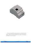
Download Inland AIS Quick operation guide
Transcript
Inland AIS
Quick operation guide
User interface
Display
Menu key
Sounder
Back key
Pilot plug (behind protective cover)
Scroll wheel
Left function key
Right function key
Select operating screen
Target list
Own vessel &
voyage data
Own dynamic
data
Target plot
Alarms
Received
messages
In normal operation the display shows one of six main operating screens.
The next screen can always be selected by pressing the ‘Screen’ function key.
Menu system
Entering text
1
10:05:20
Edit
10:05:23
2
2
INT
GPS
OK
3
4
5
6
Save
INT
GPS
OK
MAIN MENU:
1
VOYAGE DATA
MESSAGES
USER SE T TINGS
INSTALLATION
MAINTENANCE
Back
1
Screen
Own static and voyage data:
MMSI: 123456789
NAME: POSEIDON
DESTINATION: SOU T H
ETA: 06/06/10 1400Hrs
Cancel
12:34:10
INT
GPS
OK
Own static and voyage data:
MMSI: 123456789
NAME: POSEIDON
DESTINATION: SOUTH
ETA: 06/06/10 1400Hrs
Select
2
10:05:25
INT
GPS
OK
Own static and voyage
Q data:
MMSI: 123456789 R
NAME: POSEIDON S
DESTINATION: S O U TT H
U
ETA: 06/06/10 1400Hrs
V
W
Cancel
Save
201-0635:1
Receiving AIS text and safety related
messages
Receipt of AIS text messages is indicated by the presence of the
message icon in the status bar. This symbol appears whenever
unread AIS text messages are present. The messages can be
viewed by moving to the ‘Messages’ screen.
13:20:47
OK
RECEIVED MESSAGES:
DATE
TIME
FROM
29/01
10:00
MARY R...
29/01
09:55
556444321
28/01
21:45
REGENT
V iew
INT
GPS
T YPE
B R Safety
AD Safety
B R Binar y
System alarms
The status of AIS alarms is displayed on this screen. If active, but
not yet acknowledged alarm conditions exists, the alarm icon
flashes in the status bar. When a new alarm condition occurs, the
acknowledgement screen is immediately displayed.
13:20:47
OK
ALARMS
DATE
25/11
25/11
25/11
LIST:
TIME
16:13
16:11
16:11
INT
GPS
ALARM
No valid ROT...
Heading lost...
Ex ternal EPFS...
V iew
ACK
Yes
Yes
Yes
Screen
Screen
Vessel and voyage data
13:20:47
The ‘Voyage data’ menu provides quick access to the most
frequently changed Inland AIS parameters. In this menu you can
set the following parameters:
INT
GPS
OK
ALARM DETAILS:
ALARM: No valid ROT information
ID:
35
DATE:
25/11/2010
TIME:
16:13:30
ACK:
Yes
Exit
● Navigation status.
● Destination - Set the destination for the current voyage.
● ETA – Estimate the time and date of arrival at the destination.
The date format is dd/mm and the time format is hh:mm using a
24 hour clock and UTC time.
● Draught – Enter the maximum draught for your vessel in
meters. The format for this value is xx.xm (eg 02.5m). The
maximum depth is 25.5 m.
● The cargo status of the vessel as ‘Loaded’ or ‘Unloaded’.
● The number of blue cones and blue flag status for the cargo (1,
2 or 3 blue cones, or blue flag).
● The static draught of the vessel to the nearest centimetre.
● The air draught of the vessel to the nearest centimetre.
● The number of crew members (0 to 254 or “unknown” ), the
number of passengers (0-8190 or "unknown ") and other
personnel (0 to 254 or "unknown").
● The number of assisting tug boats (0 to 6).
Ship data for convoys
The inland AIS dimensions and the vessel type must be the overall
size and the type of the convoy. Enter the ship's data as follows:
1.Set the length and breadth of the convoy, and the ERI ship type.
a. From the main menu select the ‘Installation’ submenu.
b. Select “Inland AIS” and then select “Inland vessel data”.
c. Select the ‘Length’ field and enter the total length of the
convoy to the nearest 0.1m*.
d. Select the ‘Beam’ field and enter the total width of the
convoy to the nearest 0.1m*.
e. Select the ERI entry and enter the code that best
describes the convoy. A complete table of ERI vessel
type codes is provided at the rear of the user manual.
2.Configure the GNSS antenna location for the convoy.
a. From the main menu select the ‘Installation’ submenu.
b. Choose “Dimensions”
Dimensions”.
1
and
then
select
“Internal
c. Enter the dimensions A, B, C and D for the internal GNSS
antenna (antenna connected directly to the Inland AIS).
The dimensions should be rounded to the nearest whole
meter*.
2
C
B
12:34:10
MAIN MENU:
1
VOYAGE DATA
MESSAGES
USER SET TINGS
INSTALLATION
MAINTENANCE
Back
Select
3
13:20:47
OK
VOYAGE DATA:
Nav Status:
>>(15) not defined (default)
Destination:
>>Not Available
ETA:
--:--:-Draught:
Not Available
Back
INT
GPS
A
D
INT
GPS
OK
GNSS-Antenne
2
* Note that the length and width of the vessel entered in step 1,
must correspond to the antenna dimensions entered in step 2. The
dimensions entered in step 1 are rounded to the nearest whole
meter and compared with the dimensions entered in step 2. In the
case of a discrepancy during entry of the dimensions a warning is
displayed. This notice may be acknowledged by pressing the ‘OK’
function key.


