1
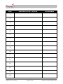
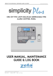
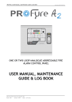
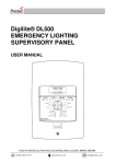
6100 SINGLE LOOP DIGITAL
ADDRESSABLE FIRE ALARM
CONTROL PANEL
USER MANUAL
Protec Fire Detection plc, Protec House, Churchill Way, Nelson, Lancashire, BB9 6RT, ENGLAND
+44 (0) 1282 717171
www.protec.co.uk
[email protected]
Document Revision Details
Issue
0
1
2
3
4
Modification Detail
Document Creation
Section 14.0 amended, miscellaneous text tidied
Refer to ECN3414
Addition of WEEE data in section 1.0
Refer to ECN3729
N93-571-87 Issue 4 NH
Page 2 of 33
Author
NH
NH
NH
NH
NH
Date
15/11/2011
17/01/2012
10/10/2013
22/06/2014
14/07/2015
© Protec Fire Detection plc 2015
Table of Contents
1.0
INTRODUCTION ..................................................................................................................................... 5
2.0
USER RESPONSIBILITIES .................................................................................................................... 6
2.1
3.0
ROUTINE TESTING OF THE SYSTEM .................................................................................................. 7
3.1
3.2
3.3
3.4
3.5
3.6
4.0
Zone Faults .................................................................................................................................... 10
System Faults ................................................................................................................................ 10
Alarm Fault .................................................................................................................................... 10
Supply Fault ................................................................................................................................... 11
Aux. Supply Fault .......................................................................................................................... 11
Repeat Panel Fault ........................................................................................................................ 11
Fire link Fault ................................................................................................................................. 11
6100 DISABLEMENT INDICATIONS ...................................................................................................11
8.1
8.2
8.3
9.0
General Fire Indicator Illuminated ................................................................................................. 10
Multifunction Zone Indicator Flashing Red .................................................................................... 10
6100 FAULT INDICATIONS ..................................................................................................................10
7.1
7.2
7.3
7.4
7.5
7.6
7.7
8.0
Multifunction Display ........................................................................................................................ 9
General Indications .......................................................................................................................... 9
Multifunction Zone Status Indications ( Row 2, first 16 zones only ) ............................................... 9
Code Entry and Menu Navigation Keys .......................................................................................... 9
Sound Alarms, Silence Alarms, Reset Panel and Mute Buzzer keys ............................................. 9
6100 FIRE INDICATIONS .....................................................................................................................10
6.1
6.2
7.0
Access Level 1 ( General User )...................................................................................................... 8
Access Level 2 ( Authorised / Trained User ) .................................................................................. 8
6100 INDICATIONS AND CONTROLS .................................................................................................. 9
5.1
5.2
5.3
5.4
5.5
6.0
Daily Inspection ............................................................................................................................... 7
Weekly Test ..................................................................................................................................... 7
Monthly Test .................................................................................................................................... 7
Quarterly Test .................................................................................................................................. 7
Annual Test...................................................................................................................................... 7
5 Yearly Test.................................................................................................................................... 7
6100 ACCESS LEVELS .......................................................................................................................... 8
4.1
4.2
5.0
Requirements of the Premises Management Named Person ......................................................... 6
Zone Disablement ......................................................................................................................... 11
Alarm Disablement ........................................................................................................................ 11
Fire Link Disablement .................................................................................................................... 11
MISCELLANEOUS INDICATIONS .......................................................................................................11
9.1
9.2
9.3
Power on Indication ....................................................................................................................... 11
Pre Alarm ....................................................................................................................................... 11
Outputs Delayed ............................................................................................................................ 11
10.0
SYSTEM DELAYS.................................................................................................................................12
11.0
COINCIDENCE OPERATION ...............................................................................................................12
12.0
6100 RESPONSE TO AN ALARM ........................................................................................................13
12.1
12.2
12.3
Automatic Detection ................................................................................................................... 13
Manual Detection ....................................................................................................................... 13
Coincidence Activation ............................................................................................................... 13
N93-571-87 Issue 4 NH
Page 3 of 33
© Protec Fire Detection plc 2015
12.4
12.5
12.6
12.7
13.0
6100 STATUS DISPLAYS ....................................................................................................................14
13.1
13.2
13.3
14.0
The System Normal Display ...................................................................................................... 14
The Fault, Disablement and Test Display .................................................................................. 14
The Fire Alarm Display .............................................................................................................. 15
6100 USER MENUS ..............................................................................................................................16
14.1
14.2
14.3
14.4
14.5
14.6
14.7
14.8
14.9
14.10
14.11
14.12
14.13
15.0
Silencing the Alarms .................................................................................................................. 13
Resetting the 6100 after an Alarm ............................................................................................. 13
New Zone in Alarm .................................................................................................................... 13
Activating the Alarms Manually .................................................................................................. 13
Entering the 6100 Menu System ............................................................................................... 16
User Menu Structure .................................................................................................................. 16
Viewing Faults and Disablements .............................................................................................. 17
Clearing System Faults .............................................................................................................. 18
Testing the Front Panel Indications ........................................................................................... 18
Setting a Zone Into Walk Test Mode ......................................................................................... 19
Disabling a Zone ........................................................................................................................ 19
Disabling Alarm and Fire Link Outputs ...................................................................................... 20
Setting the Date and Time ......................................................................................................... 20
Viewing the Alarm Counter ........................................................................................................ 21
Viewing the Fire Event Log ........................................................................................................ 21
Viewing the General Event Log ................................................................................................. 22
Exiting the Menus ...................................................................................................................... 22
6100 FIRE BRIGADE PANEL OPERATION (AUSTRALIAN MARKETS) ..........................................23
15.1
15.2
15.3
15.4
Silence Buzzer Button ................................................................................................................ 23
Silence Alarms Button ................................................................................................................ 23
Reset Button .............................................................................................................................. 23
Disable Button ............................................................................................................................ 23
16.0
APPENDIX 1 - 6100 SYSTEM SET UP RECORD ................................................................................24
17.0
APPENDIX 2 - 6100 EVENT LOG ........................................................................................................27
18.0
APPENDIX 3 – 6100 OPERATION QUICK REFERENCE GUIDE ......................................................32
18.1
18.2
18.3
18.4
18.5
18.6
18.7
18.8
Entering Access Level 2 ............................................................................................................ 32
Returning to Access Level 1 ...................................................................................................... 32
Muting the Internal Buzzer and accepting Current Faults ......................................................... 32
Sounding the Alarms.................................................................................................................. 32
Silencing the Alarms .................................................................................................................. 32
Resetting the 6100 ..................................................................................................................... 32
Testing the Indicators and Internal Buzzer ................................................................................ 32
Setting the Date and Time ......................................................................................................... 32
N93-571-87 Issue 4 NH
Page 4 of 33
© Protec Fire Detection plc 2015
1.0
Introduction
The Protec 6100 Fire Alarm Control Panel has been designed and manufactured in the United Kingdom and
complies fully with current standards dictating fire alarm system design practice ( EN54 parts 2 and 4 ).
The 6100 is a 32 zone single loop fire alarm control panel that uses digital addressable technology to
communicate with Protec 6000PLUS series loop devices ( automatic detectors, Manual Call Points,
sounders, interfaces etc. ).
As the integrity and reliability of a fire alarm system is vital, the 6100 continuously monitors all critical paths
for faults. The fire detection / alarm loop devices and wiring are constantly monitored to check for faults. The
integrated power supply regularly performs self checks to ensure it is in full working order and that the
stand-by batteries are in a good state.
Any faults detected are reported on the front panel display of the 6100, a fault output is also provided which
may be connected to external systems ( a remote monitoring centre, for example ) to signal that the 6100
has a fault and attention is required.
Please be aware that the 6100 is supplied to various countries, the particular panel variant typically having
slight operational differences dependent on the target market.
There are no user serviceable parts inside the 6100. A competent person trained to undertake
such work MUST carry out any internal maintenance work. A separate installation and
commissioning manual is available.
This equipment has been manufactured in conformance with the requirements of all
applicable EU council directives and regulations.
Electrical or electronic devices that are no longer serviceable must be collected separately and
sent for environmentally compatible recycling (in accordance with the European Waste
Electrical and Electronic Equipment Directive). To dispose of old electrical or electronic
devices, you should use the return and collection systems put in place in the country
concerned.
The policy of Protec Fire Detection plc is one of continuous improvement. As such we reserve the right to
make changes to product specifications at any time and without prior notice. Errors and omissions excepted.
N93-571-87 Issue 4 NH
Page 5 of 33
© Protec Fire Detection plc 2015
2.0
User Responsibilities
The registered owner of the fire alarm system has specific responsibilities regarding the installation, testing
and maintenance of the fire alarm system.
BS5839 Pt 1: 2013 Section 7 states that the user of the fire alarm system must appoint a single named
person to supervise all matters regarding the fire alarm system.
Summarised below are the responsibilities expected of the named person,
It is strongly advised that a full copy of BS5839 Pt 1: 2013 is obtained and thoroughly read
and understood.
2.1
Requirements of the Premises Management Named Person
•
Ensure that the fire alarm equipment is checked at least once every 24 hours to ensure there are
no faults on the system. Report any faults to the site maintenance manager.
•
Ensure that arrangements are in place for correct testing of the fire alarm system ( as specified
in BS5839 Pt 1: 2013 Section 6, summarised in section 3.0 of this document ).
•
Ensure that the system event log is kept up to date and is available for inspection by any
authorised person when required. An example event log is included in appendix 15.0 of this
document.
•
Ensure that all occupants of the protected premises are trained how to use the system properly
and that they are aware of what action to take in the event of an alarm.
•
Ensure that false alarms are minimised.
•
Ensure all detectors and manual call points are not obstructed. Detectors must have at least
500mm clear space preserved in all directions around them.
•
Establish a liaison with those responsible for changes in, or maintenance of the building fabric.
•
Ensure that when changes are made to the system, record drawings and operating instructions
are updated.
•
Ensure that, where necessary, a suitable zone plan is displayed and kept up to date.
•
Ensure that any relevant spare parts for system maintenance are held within the premises.
N93-571-87 Issue 4 NH
Page 6 of 33
© Protec Fire Detection plc 2015
3.0
Routine Testing of the System
Recommendations for testing of the system are detailed in BS5839 Pt 1: 2013 ( section 6 )
The routine testing is briefly detailed below.
3.1
Daily Inspection
•
•
3.2
Check that the Supply Present indicator is illuminated.
Check for any faults on the system and report these to the site maintenance manager.
Weekly Test
Perform the daily test recommended in 3.1 and;
During the test you may wish to temporarily place the zone to be tested into test mode
( consult section 14.9 )
3.3
•
Perform an indicator test ( lamp test ) to check the integrity of the front panel indications, and
internal buzzer.
•
Ensure no Manual Call Points or detectors are obstructed.
•
Operate a Manual Call Point or detector during normal working hours to ensure the fire alarm
system operates correctly.
•
A different Manual Call Point or detector on a different zone should be tested each week, in this
way all the devices on all the zones are tested.
•
Ensure the system sounders are operational.
•
Ensure the sounders are not operated for longer than 30 seconds during testing. The occupants
of the building can then distinguish genuine alarms.
Monthly Test
Perform the weekly test recommended in 3.2 and;
3.4
•
If an automatic generator is used as part of the mains failure back-up system it should be started
up once each month by simulated failure of the normal power supply, and then run in this mode
for at least 1 hour.
•
Visually inspect the stand-by batteries and their connections. Check that the batteries are
capable of supplying the alarm sounders.
Quarterly Test
Perform the monthly test recommended in 3.3 and;
•
3.5
Ensure the system event log is up to date and all entries are correct. Check that any faults noted
have been rectified.
Annual Test
Perform the quarterly test recommended in 3.4 and;
•
3.6
Test every detector, Manual Call Point and all auxiliary equipment for correct functionality.
5 Yearly Test
Perform the Annual test recommended in 3.5 and;
•
Carry out a full wiring check in accordance with the testing and inspection requirements of the
relevant National wiring regulations ( I.E.E regulations for the UK ).
N93-571-87 Issue 4 NH
Page 7 of 33
© Protec Fire Detection plc 2015
4.0
6100 Access Levels
The 6100 has two access levels to allow users of different authorisation levels access to various parts of the
system. The access levels and a description of functions available are given in the next sections.
4.1
Access Level 1 ( General User )
Access level 1 allows the general user to view the status of the 6100 at any time. Zone fire, fault,
disablement and test states are clearly displayed as are any current system faults and disablements.
Full detail of the front panel display is given in the next section.
The following functions may be performed at access level 1.
•
4.2
Entering access level 2
Access Level 2 ( Authorised / Trained User )
Access level 2 allows the authorised user access to various critical system functions.
To enter access level 2 either enter the user code using the numbered keypad or insert and turn the
fire man’s key-switch ( depending on the particular model purchased ).
When access level 2 has been entered the ‘User Level Entered’ screen will be displayed and access
level 2 menus are available after an addition ↵ key press.
To return to access level 1 scroll to the EXIT MENU function and press the ↵ key.
As a security measure the 6100 will return to access level 1 if no key activity has been
detected for 1 minute.
The following functions are accessible at access level 2.
•
•
•
•
•
•
•
•
•
•
•
•
•
•
•
•
•
Sounding the alarms
Silencing an alarm condition
Resetting the panel after alarm activation
Accepting current faults or alarms ( Mute Buzzer )
Viewing current faults
Viewing current disablements
Clearing system faults
Testing the front panel indications, and internal buzzer
Exchanging a loop device for another device of the same type
Programming a single zone into walk test mode
Disabling a zone
Disabling the Fire Link ( if used )
Disabling alarm outputs
Viewing the alarm counter
Setting the time and date
Viewing the fire event log
Viewing the general event log
N93-571-87 Issue 4 NH
Page 8 of 33
© Protec Fire Detection plc 2015
5.0
6100 Indications and Controls
The 6100 has a comprehensive front panel display enabling the current state of the 6100 to be rapidly
determined. Figure 5.0 shows the indications and controls.
Figure 5.0
6100 front panel indications and controls.
PROTEC 6100
CONTROL PANEL
LCD
SYSTEM normal
Row 1
Row 2
Keypad
Column 1
5.1
Column 2
Multifunction Display
The 6100 gives a clear indication of the current status of the 6100 on the Liquid Crystal Display ( LCD ).
Under normal conditions the LCD shows the System Normal screen. This changes to the status display
screen if the 6100 has faults, disablements or tests present.
5.2
General Indications
Row 1 comprises the General Fire, Fault, Disablement and Test indicators. These indications give clear
indication that the 6100 has at least one Fire, Fault, Disablement or Test condition.
5.3
Multifunction Zone Status Indications ( Row 2, first 16 zones only )
Zone fires are indicated when the zone indicator flashes red, and are always accompanied by the General
Fire indicator.
Zone faults are indicated when the zone indicator flashes yellow and are always accompanied by the
General Fault indicator.
Zone disablements are indicated when the zone indicator lights steady yellow and are always accompanied
by the General Disablement indicator.
Zones in test mode are indicated when the zone indicator lights steady yellow and are always accompanied
by the General Test indicator.
5.4
Code Entry and Menu Navigation Keys
The keys in the centre of the 6100 are used to enter the user code ( using keys 1, 2, 3 and 4 ) and are also
used to navigate the menu system.
5.5
Sound Alarms, Silence Alarms, Reset Panel and Mute Buzzer keys
These keys are used to control panel functions. The user code must be entered before the keys become
operational.
N93-571-87 Issue 4 NH
Page 9 of 33
© Protec Fire Detection plc 2015
6.0
6100 Fire Indications
The 6100 displays fire information on the LCD along with the General Fire indicator and the relevant red
zone indicators. The following sections details the meaning of each indicator.
6.1
General Fire Indicator Illuminated
The 6100 has detected a fire on one of its zones, or has been activated from another piece of
equipment connected to its Remote Alarm input.
The building fire plan should be executed immediately
6.2
Multifunction Zone Indicator Flashing Red
The 6100 has detected a fire in the zone shown. The General Fire indicator will always accompany
this and the internal buzzer will be fast pulsing. Indication of a zone fire always overrides a zone
fault, disablement or test indication.
7.0
6100 Fault Indications
When the 6100 has detected a fault in any of the critical operating paths of the system it will display this on
the front panel display. The internal buzzer will also pulse slowly.
The General Fault indicator will be illuminated and is always accompanied by other indicator(s) detailing the
exact fault.
In general, fault indicators flash until the fault is accepted ( by pressing the Mute Buzzer button in access
level 2 ) the fault indicator then illuminates steadily and the internal buzzer will be muted. Further faults
activate the buzzer again.
In the event of any fault the following action should be taken:
•
Investigate the fault, then, at access level 2, accept the fault by pressing the Mute Buzzer button.
•
Note the fault down in the Logbook and take action to remedy the fault. In all cases expert advice
should be sought.
When the fault has been rectified the fault indicator will automatically extinguish.
The following sections give descriptions of each fault.
7.1
Zone Faults
The 6100 displays any faults in the first 16 zones on the multifunction zone indicators. All Zone faults
are also displayed on the LCD. The General Fault indicator will be illuminated accompanied by the
relevant zone indicator flashing yellow. Pressing Mute Buzzer will mute the buzzer but WILL NOT
make the zone indicator go steady.
7.2
System Faults
The 6100 performs regular self tests to ensure the software is working correctly. If a fault is detected
in software operation a System Fault is declared. This is a latching fault and can only be cleared by
using the ‘clear system faults’ menu.
7.3
Alarm Fault
A fault has been detected on one or more of the alarm devices connected to the loop, or one or both
of the conventional alarm outputs has a fault. One or more alarm devices may no longer operate
correctly.
N93-571-87 Issue 4 NH
Page 10 of 33
© Protec Fire Detection plc 2015
7.4
Supply Fault
A fault has been detected in the power supply of the 6100. This may be because the local mains
supply has failed or because the internal stand-by batteries or circuitry are faulty. The General Fault
indicator will be illuminated accompanied by the PSU Fault indicator.
7.5
Aux. Supply Fault
A fault has been detected with the Auxiliary 24V supply output of the 6100. There may no longer be
an auxiliary supply to external devices or the auxiliary devices are drawing too much current. The
General Fault indicator will be illuminated accompanied by the ‘Aux Supply Fault’ indicator.
7.6
Repeat Panel Fault
A fault has been detected on a repeat panel connected to the 6100, or the wiring to the repeat panel
is faulty. The ‘General Fault’ indicator will be illuminated, accompanied by the Repeat Fault indicator.
7.7
Fire link Fault
A fault has been detected on the monitored fire link path. This may be a wiring fault or a fire link
interface fault. The connection to the fire station link is no longer reliable. Expert advice should be
sought immediately. The General Fault indicator will be illuminated accompanied by the Fire Link
Fault indicator.
8.0
6100 Disablement Indications
8.1
Zone Disablement
Fires and faults from the disabled zone are prevented. Detectors and Manual Call Points in this zone
will not trigger the 6100 into a fire condition.
8.2
Alarm Disablement
Activation to and faults from alarm outputs are prevented. The sounders will not operate in the event
of a fire.
8.3
Fire Link Disablement
Activation and faults on the fire link output are inhibited. The fire link will not activate in the event of a
fire.
9.0
Miscellaneous Indications
9.1
Power on Indication
This indication illuminates when the 6100 is powered up from mains or its internal batteries.
9.2
Pre Alarm
One or more loop detectors are near to their full alarm condition. It is recommended that the area
where the device is located is investigated and appropriate action taken.
9.3
Outputs Delayed
This indicator will be illuminated if the commissioning engineer has programmed alarm output, or fire
link activation delays into the system. The alarms, or fire link may not activate immediately in the
event of a fire.
N93-571-87 Issue 4 NH
Page 11 of 33
© Protec Fire Detection plc 2015
10.0 System Delays
Delays may have been programmed into the 6100 at commissioning time to allow a predetermined delay
time from zone activation until,
•
•
The alarm outputs activate
The fire link activates
Delays may be used in order to allow time for the cause of the activation to be investigated by the premises
management. If the cause of the activation is found to be legitimate the alarm outputs can be manually
activated. If the cause of the activation is found to be false the 6100 can be reset.
The 6100 system set-up chart must be consulted to determine exactly which outputs have been delayed and
how the delay time has been set up.
If the Silence Alarms button is pressed while a delay is running, the alarm outputs will not be activated when
the delay expires. The global fire contacts, however, will still be activated.
Delays only apply to automatic detector activations. A manual activation on a zone
( activating a Manual Call Point ) always overrides all current delays.
11.0 Coincidence Operation
At the time of commissioning, the system may have been programmed to operate in ‘coincidence’ mode.
Coincidence operation is used in order to minimise the effects of false alarms.
Coincidence operation can be used to prevent alarm outputs in certain areas from triggering until two, or
more activations have been received from a certain group of devices.
This allows the initial activation to be investigated before the 6100 activates the full alarm outputs.
N93-571-87 Issue 4 NH
Page 12 of 33
© Protec Fire Detection plc 2015
12.0 6100 Response to an Alarm
12.1
Automatic Detection
If a detector ( smoke, heat etc. ) activates on a zone of the 6100 this is known as an automatic
operation. The 6100 responds by ;
•
•
•
•
•
•
12.2
Illuminating the ‘General Fire’ indicator.
Flashing the relevant red zone fire indicator and displaying on the display.
Fast pulsing of the internal buzzer.
Activating alarm outputs as programmed, after any delays have expired.
Activating the Fire Link output after any programmed delays have expired.
Activating the Global Fire contacts.
Manual Detection
If a Manual Call Point is operated on the zone of a 6100 this is known as manual operation. The
6100 responds by;
•
•
•
•
•
•
12.3
Illuminating the ‘General Fire’ indicator.
Flashing the relevant zone fire indicator.
Fast pulsing of the internal buzzer.
Immediately activating alarm outputs as programmed.
Activating the Global Fire contacts.
Immediately activating the Fire Link output.
Coincidence Activation
Please see section 11.0
12.4
Silencing the Alarms
Pressing Silence Alarms when in access level 2 will silence alarm outputs. A further activation will
re-sound the alarms.
12.5
Resetting the 6100 after an Alarm
After the cause of the alarm has been determined ( and entered in the log by the authorised user )
the 6100 can be reset if required. Manual Call Points, if triggered, must first be reset locally. In
access level 2 press Silence Alarms then press Reset Panel. The 6100 will reset any latched
devices on its loop. This process takes about 20 seconds during which time the 6100 will not detect
new fires.
12.6
New Zone in Alarm
If a new zone or a previously silenced zone goes into alarm, the 6100 will re-activate the alarms and
re-sound the internal buzzer.
12.7
Activating the Alarms Manually
Press Sound Alarms when in access level 2 to evacuate the building. Alarm outputs will be activated
as programmed but the Global Fire Contacts and the Fire Link Interface WILL NOT be activated.
N93-571-87 Issue 4 NH
Page 13 of 33
© Protec Fire Detection plc 2015
13.0 6100 Status Displays
At any given time the 6100 will be in one of three main states. These are the normal condition, the fault /
disablement/test condition or the fire condition.
13.1
The System Normal Display
When the 6100 does not have any fires, faults, disablements or tests it is in the System Normal condition.
In this state the 6100 will have it’s power on indicator illuminated and the LCD will show the System Normal
display, as shown in figure 13.0.
Figure 13.0 – The System Normal Display
Protec 6100
Control panel
Dd / mm / yy
13.2
HH:MM:ss
The Fault, Disablement and Test Display
If the system has one or more faults, disablements or tests the 6100 will display this as shown in
Figure 13.1.
Faults, disablements and tests are always accompanied by the relevant general indicator, plus separate
indications detailing the individual condition.
The authorised user may enter the access level 2 code to accept the current system status by pressing the
Mute Buzzer key, or retrieve more detailed information about individual faults or disablements by entering
the 6100 menu system.
Faults that have not been accepted will, in general, use a pulsing indication. This then changes to steady
when the fault is accepted.
Figure 13.1 – The Fault, Disablement and Test Display
System status
1 zone in test
3 disablements
2 faults
N93-571-87 Issue 4 NH
Page 14 of 33
© Protec Fire Detection plc 2015
13.3
The Fire Alarm Display
The 6100 enters the alarm state if one or more loop devices have triggered ( this may be because an
automatic detector has sensed a fire, or a Manual Call Point has been operated ).
The 6100 will activate its alarms as dictated by the system programming when commissioned.
The General Fire indicator will illuminate and ( if the alarm is in zones 1 to 16 ) the multifunction zone
indicator will flash red.
The LCD shows the fire display ( overriding any normal or fault displays ) as shown in Figure 13.2.
The display follows the format of displaying the first zone into fire on line 1, Latest zone into fire on line 2 and
the total number of zones in fire on line 3.
Figure 13.2 – 6100 Alarm Condition Display
First fire zone 1
Latest fire zone 32
Fire in 32 zones
Enter for more info
The authorised user may press the ↵ key at this screen to retrieve more detailed information about any
current fires. The display will show details of the first device to generate an alarm , pressing the ▲ or ▼ keys
will rotate the displayed information showing the zone text for the device, the address text for the device then
the time and date at which the device generated the alarm.
Pressing the ◄ or ► keys scrolls through any further devices in fire.
The screen automatically returns to the standard 6100 fire display if no buttons are pressed for 30 seconds.
Figure 13.3 – Example of display showing information for the first device that generated an alarm
Fire 1 of 3
Address 2 optical
zone 1
Dd / mm / yy HH:MM:ss
N93-571-87 Issue 4 NH
Page 15 of 33
© Protec Fire Detection plc 2015
14.0 6100 User Menus
14.1
Entering the 6100 Menu System
When the user code is entered at access level 1 the ‘user level accessed’ screen will be displayed as shown
in figure 14.0. The Sound Alarms, Silence Alarms, Reset Panel and Mute Buzzer buttons are now enabled.
Pressing the enter key (↵
↵) will access the user menus, navigation of the menu options is achieved by using
the ◄ or ► keys. The menu structure is shown in figure 14.0. Pressing ↵ on a particular menu option will
accept the option.
14.2
User Menu Structure
Figure 14.0
User Menu Structure
View Faults
See Section 14.3
View Disablements
See Section 14.3
Clear System Faults
See Section 14.4
Test Indications
See Section 14.5
Zone Options
See Sections 14.6 / 14.7
Disable Options
See Section 14.8
Set Date and Time
See Section 14.9
View Alarm Count
See Section 14.10
View Fire Event Log
See Section 14.11
View General Event Log
See Section 14.12
Exit Menu
See Section 14.13
N93-571-87 Issue 4 NH
Page 16 of 33
© Protec Fire Detection plc 2015
14.3
Viewing Faults and Disablements
The VIEW FAULTS and the VIEW DISABLEMENTS menus allow the user to view any faults or disablements
currently on the 6100. Both these menus have the same basic format.
1.
Enter the user code supplied with the system and press the ↵ key to access the menu system.
2.
Using the ◄ and ► keys navigate to the VIEW FAULTS or VIEW DISABLEMENTS menu as
required, and press the ↵ key.
3.
The first event is displayed, ( illustrated in figure 14.1 / 14.3 ) If there are no current events the 6100
will show the screen illustrated in figure 14.2 / 14.4, and an error tone will be issued.
4.
Use the ◄ and ► keys to navigate to the previous or next event.
5.
Use the ▲ and ▼ keys to toggle between the time of the event, the location text or the zone text.
Please note that depending on the event type some of the display options will not be available.
6.
Press the ↵ key to exit the menu and return to the main menu.
Figure 14.1
View faults display, initial screen
fault 1 of 6
zone fault
zone 1
Dd / mm / yy HH:MM:ss
Figure 14.2
No Faults to View Display
View faults
No events to view
Figure 14.3
View Disablements Display
Dis 1 of 6
Zone disablement
Zone 3
Dd / mm / yy HH:MM:ss
Figure 14.4
No Disablements Display Screen
View disablements
No events to view
N93-571-87 Issue 4 NH
Page 17 of 33
© Protec Fire Detection plc 2015
14.4
Clearing System Faults
The CLEAR SYSTEM FAULTS menu allows the user to reset any latching system faults that are on the
system.
1.
Enter the user code supplied with the system and press the ↵ key to access the menus.
2.
Using the ◄ and ► keys navigate to the CLEAR SYSTEM FAULTS menu and press the ↵ key.
Any current system faults will be cleared and the system fault indicator will extinguish.
Figure 14.5
Clear System Faults display
Main menu
Clear system faults
14.5
Testing the Front Panel Indications
The TEST INDICATIONS menu is used to test the functionality of the front panel indicators, LCD and internal
buzzer.
1.
Enter the user code supplied with the system and press the ↵ key to access the menus.
2.
Using the ◄ or ► keys navigate to the TEST INDICATIONS menu press the ↵ key to start the test.
All indications will illuminate, the LCD will display its test message ( as shown in figure 14.6 ) and the
internal buzzer will sound. The test will automatically stop after 5 seconds ( do not press any buttons
during this time ).
Figure 14.6
Test Indications Display
***lcd
***lcd
***lcd
***lcd
N93-571-87 Issue 4 NH
*
*
*
*
test
test
test
test
*line
*line
*line
*line
Page 18 of 33
*1
*2
*3
*4
***
***
***
***
© Protec Fire Detection plc 2015
14.6
Setting a Zone Into Walk Test Mode
The 6100 allows a single zone at a time to be set to walk test mode. In walk test mode a loop device can be
functionally tested and, after a predetermined time, the 6100 will automatically reset.
1.
Enter the user code supplied with the system and press the ↵ key to access the menus.
2.
Using the ◄ and ► keys navigate to the ZONE OPTIONS menu and press the ↵ key to access the
menu (Figure 14.7).
3.
Using the ◄ and ► keys select the desired zone to be tested.
4.
Using the ▲ and ▼ keys move the cursor to the TESTING option and set testing to ON or OFF
using the ◄ and ► keys.
5.
When all zone programming has been finished press the ↵ key to return to the main menu.
The zone in walk test mode will illuminate the global test indicator, along with the specific zone indicator.
Activations from a zone programmed into walk test mode will not activate the global fire
contacts or Fire Link output. Remember to take the zone out of walk test mode when testing
has been completed.
14.7
Disabling a Zone
The 6100 allows zones to be disabled. This means that faults and activation’s are inhibited. Fires on a
disabled zone will not be detected.
1.
Enter the user code supplied with the system and press the ↵ key to access the menus.
2.
Using the ◄ and ► keys navigate to the ZONE OPTIONS menu and press the ↵ key to access the
menu (Figure 14.7).
3.
Using the ◄ and ► keys select the desired zone to be disabled.
4.
Using the ▲ and ▼ keys move the cursor to the DISABLED option and using the ◄ and ► keys set
to ON ( disabled ) or OFF ( not disabled ).
5.
Press the ↵ key to return to the main menu.
A zone disablement will illuminate the global disablement indicator, along with the specific zone indicator.
It is possible that loop devices in a zone that is about to be normalised ( removed from
disablement ) may be in alarm. If this is the case the 6100 will display a warning screen then
automatically reset.
Figure 14.7
Zone Options display
zone options
Zone
1
Disabled
on
Testing
off
N93-571-87 Issue 4 NH
Page 19 of 33
© Protec Fire Detection plc 2015
14.8
Disabling Alarm and Fire Link Outputs
The user can disable certain 6100 functions to suit current site conditions.
•
The panel alarm outputs ( loop sounders and conventional alarm outputs ) can be disabled. Doing this
means that if the panel enters the alarm condition no sounders will operate. Faults from alarm devices
will not be reported.
•
The fire link output may also be disabled, which will prevent the fire link from activating, or generating
faults.
Please consult the system set-up record ( appendix 1 ) before making adjustments to these
critical parts of the system. If it is unknown why the system has been configured in this way
DO NOT continue.
1.
Enter the user code supplied with the system and press the ↵ key to access the menus.
2.
Using the ◄ and ► keys navigate to the DISABLE OPTIONS menu and press ↵ to access the menu
(Figure 14.8).
3.
Press the ▲ and ▼ keys to highlight the option to be edited ( the flashing cursor indicates which
option is currently selected )
4.
Press the ◄ and ► keys to toggle the state of the highlighted option.
5.
Press the ↵ key to accept the changes and return to the main menu.
Figure 14.8
Disable options display
disable
ALARMS
Fire link
Buzzer
14.9
OPTIONS
disabled
enabled
enabled
Setting the Date and Time
The SET DATE AND TIME menu allows the user to set the current date and time used by the 6100. The time
is entered in 24-hour format and is used when time stamping alarm, fault, disablement or test events.
1.
Enter the user code supplied with the system and press the ↵ key to access the menus.
2.
Using the ◄ and ► keys navigate to the SET DATE AND TIME menu and press the ↵ key. The
currently set date and time will be displayed ( Figure 14.9 ).
3.
Press the ◄ and ► keys to move the flashing cursor to the number to be edited, then press the ▲
and ▼ keys to set the chosen value.
4.
Press the ↵ key to save the time and date and return to the main menu.
Figure 14.9
Set Date and Time display
Set date and time
dd / mm / yy
N93-571-87 Issue 4 NH
Page 20 of 33
HH:MM
© Protec Fire Detection plc 2015
14.10 Viewing the Alarm Counter
The VIEW ALARM COUNT menu allows the user to view the total number of times the 6100 has entered the
alarm state since the alarm counter was last reset.
1.
Enter the user code supplied with the system and press the ↵ key to access the menus.
2.
Using the ◄ and ► keys navigate to the VIEW ALARM COUNT menu press the ↵ key to enter the
view alarm counter display ( figure 14.10 ).
3.
Press the ↵ key to return to the main menu.
Figure 14.10
Example View Alarm Counter Display
View alarm count
5 alarms
14.11 Viewing the Fire Event Log
The VIEW FIRE EVENT LOG menu allows the user to view data about historic fire events.
1.
Enter the user code supplied with the system and press the ↵ key to access the menus.
2.
Using the ◄ and ► keys navigate to the VIEW FIRE EVENT LOG menu and press the ↵ key.
3.
The latest fire is displayed first, as shown in figure 14.11. If there are no fires in the log the 6100 will
show the screen illustrated in figure 14.12, and issue an error tone.
4.
Use the ◄ and ► keys to view the previous or next event.
5.
Press the ↵ key to exit this menu and return to the main menu.
Figure 14.11
Illustration of View Fire Event Log display
Event 001
Device in alarm
DD / MM / YY HH:MM:SS
Address 001
Figure 14.12
No Fire Events display
View fire events
No events to view
N93-571-87 Issue 4 NH
Page 21 of 33
© Protec Fire Detection plc 2015
14.12 Viewing the General Event Log
The VIEW GENERAL EVENT LOG menu allows the user to view any historic non-fire events.
1.
Enter the user code supplied with the system and press the ↵ key to access the menus.
2.
Using the ◄ and ► keys navigate to the VIEW GENERAL EVENT LOG menu and press the ↵ key.
3.
The latest event is displayed first, as shown in figure 14.13 If there are no events in the log the 6100
will show the screen illustrated in figure 14.14, and issue an error tone.
4.
Use the ◄ and ► keys to view the previous or next event.
5.
Press the ↵ key to exit this menu and return to the main menu.
Figure 14.13
Illustration of View General Event Log display
Event 001
Device fault
DD / MM / YY HH:MM:SS
address 001
Figure 14.14
No General Events display
View general events
No events to view
14.13 Exiting the Menus
The EXIT MENU operation allows the user to exit from the menu and save any changes that may have been
made.
1.
Using the ◄ and ► keys navigate to the EXIT MENU menu and press the ↵ key.
2.
If no changes have been made the 6100 will return to the system status display. If changes have
been made then the save changes screen ( Figure 14.15 ) will be displayed. Using the ▲ and ▼keys
select whether to save changes.
3.
Press the ↵ key to accept and return to the status display screen.
Figure 14.15
Save Changes display
Save all changes ?
YES
N93-571-87 Issue 4 NH
Page 22 of 33
© Protec Fire Detection plc 2015
15.0 6100 Fire Brigade Panel Operation (Australian Markets)
If the 6100 is equipped with the optional Fire Brigade Panel (FBP) controller, illustrated in figure 15.0.
The FBP controls are enabled by use of a special key.
15.1
Enable Key
Operation of FBP controls is inhibited until the key is inserted into the key-switch, and rotated
clockwise by 90 degrees. Confirmation of this is given by illumination of the 'OPERATED' indicator
and audible feedback from the internal buzzer.
Once activated all button controls (detailed below) are available.
If programmed to do so the LCD on the 6100 will turn off upon activation of the FBP
controller.
15.2
Silence Buzzer Button
Momentary pressing of the SILENCE BUZZER button allows the user to silence the audible
indication (internal buzzer) of the 6100.
15.3
Silence Alarms Button
Momentary pressing of the SILENCE ALARMS button allows the user to silence any active alarm
outputs. Subsequent presses of the SILENCE ALARMS button toggles between re-sounding and
silencing any currently active alarms.
15.4
Reset Button
Momentary pressing of the RESET button allows the user to reset the panel following a fire
condition. A panel reset will only occur following a silence of the alarm outputs and should only be
reset after the cause of the alarm has been determined (and entered in the fire alarm log book).
15.5
Disable Button
Momentary pressing of the DISABLE button allows the user to disable any zones that are currently in
a fire condition. A zone disablement is only permitted following a silence of the alarm outputs.
Following a panel reset the zones will require normalising using the panel menus
(refer to section 14.7).
Figure 15.0
Fire Brigade Panel Controller
Enable Key-switch
Control Buttons
OPERATED
indicator
N93-571-87 Issue 4 NH
Page 23 of 33
© Protec Fire Detection plc 2015
Appendix 1 - 6100 System Set up Record
The engineer in charge of commissioning the system must complete this sheet. It is the only record of how
the system has been configured and, as such, should be safely stored for future reference.
COMMISSIONING DETAILS
System Commissioned By
Company
Contact Details
Authorised User Code
CONNECTION
CONNECTED TO / PROGRAMMING
RESULT
Global Fault
Global Fire
Class Change
Remote Alarm
Fire link
Auxiliary 24V
Notes:
N93-571-87 Issue 4 NH
Page 24 of 33
© Protec Fire Detection plc 2015
ZONE
ZONE DESCRIPTION / LOCATION
PROGRAMMING
1
2
3
4
5
6
7
8
9
10
11
12
13
14
15
16
N93-571-87 Issue 4 NH
Page 25 of 33
© Protec Fire Detection plc 2015
ZONE
ZONE DESCRIPTION / LOCATION
PROGRAMMING
17
18
19
20
21
22
23
24
25
26
27
28
29
30
31
32
N93-571-87 Issue 4 NH
Page 26 of 33
© Protec Fire Detection plc 2015
16.0 Appendix 2 - 6100 Event Log
The person appointed in charge of the fire alarm system should complete the relevant section of this sheet
whenever an event ( fire or fault ) occurs on the system.
Name of the person in charge of the fire alarm system
…………………………………………………………………………………………………...
Contact details of above person
…………………………………………………………………………………………………...
Contact details of maintenance person / company
………………………………………………………………………………………………………..….
……………………………………………………………………………………………………..…….
……………………………………………………………………………………………………………
……………………………………………………………………………………………………………
N93-571-87 Issue 4 NH
Page 27 of 33
© Protec Fire Detection plc 2015
6100 Fire Alarm System Event Log
DATE
TIME
ZONE
N93-571-87 Issue 4 NH
DETAILS
ACTION REQUIRED
Page 28 of 33
COMPLETED
NAME
© Protec Fire Detection plc 2015
DATE
TIME
ZONE
N93-571-87 Issue 4 NH
DETAILS
ACTION REQUIRED
Page 29 of 33
COMPLETED
NAME
© Protec Fire Detection plc 2015
DATE
TIME
ZONE
N93-571-87 Issue 4 NH
DETAILS
ACTION REQUIRED
Page 30 of 33
COMPLETED
NAME
© Protec Fire Detection plc 2015
DATE
TIME
ZONE
N93-571-87 Issue 4 NH
DETAILS
ACTION REQUIRED
Page 31 of 33
COMPLETED
NAME
© Protec Fire Detection plc 2015
17.0 Appendix 3 – 6100 Operation Quick Reference Guide
17.1
Entering Access Level 2
Using the keypad enter the user code ( supplied with the control panel’s documentation ).
17.2
Returning to Access Level 1
Press the ↵ key at the EXIT MENU option.
17.3
Muting the Internal Buzzer and accepting Current Faults
From access level 2 press Mute Buzzer.
17.4
Sounding the Alarms
From access level 2 press Sound Alarms.
17.5
Silencing the Alarms
From access level 2 press Silence Alarms. A further activation will re-sound the alarms.
17.6
Resetting the 6100
Determine the cause of the alarm before resetting the panel
Ensure the cause of the alarm has been removed, and any Manual Call Points locally reset.
From access level 2 press Silence Alarms then press Reset Panel.
17.7
Testing the Indicators and Internal Buzzer
From access level 2 navigate to the TEST INDICATIONS menu then press ↵ the 6100 will perform
a full indicator test. Do not press any buttons while the test is in progress.
17.8
Setting the Date and Time
From access level 2 navigate to the SET DATE AND TIME menu then press ↵. Enter the time and
date in 24 hour format.
N93-571-87 Issue 4 NH
Page 32 of 33
© Protec Fire Detection plc 2015
Designed and manufactured in the United Kingdom
N93-571-87 Issue 4 NH
Page 33 of 33
© Protec Fire Detection plc 2015