1
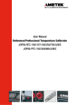
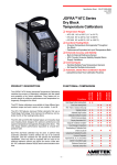
User manual Temperature Calibrator JOFRA ITC-155/320/650 A Copyright 2005 AMETEK DENMARK A/S (123311-UK) 19-09-2005 FIG. 1 1 2 3 C AT BR ION I NS TR U M EN T S 4 5 - + A LI Switch Test RS232 6 9 10 8 7 19-09-2005 FIG. 2 CALIBRATION INSTRUMENTS SWITCH TEST AUTO STEP ESC MENU °C °F °C °F min 19-09-2005 °C °C 19-09-2005 19-09-2005 19-09-2005 19-09-2005 List of contents 1.0 Introduction..................................................................... 2 1.1 List of equipment received ..................................................2 2.0 Safety instructions ......................................................... 3 3.0 Operating the calibrator ................................................. 6 3.1 3.2 3.3 3.4 3.5 3.6 3.7 3.8 3.9 Before use ...........................................................................6 Keyboard .............................................................................8 Display.................................................................................8 Connections ........................................................................9 Calibrator functions - overview ............................................9 Selecting the set-temperature .............................................9 SWITCH TEST ..................................................................10 AUTO STEP ......................................................................11 MENU................................................................................12 4.0 Setting the main voltage and replacing the fuses .... 13 5.0 After use ........................................................................ 15 123311 01 1 1.0 Introduction ITC-calibrators are temperature calibrators designed to calibrate temperature sensors and temperature switches. Read this manual carefully before using the instrument and make sure that all safety instructions and warnings are observed. 1.1 List of equipment received When you receive the instrument, the following should be enclosed: • • • • • • • • • • 2 1 calibrator 1 mains cable 1 set of test cables (1 black, 1 red) 1 insertion tube 1 tool for insertion tube 1 traceable certificate 1 reference manual 1 user manual RS232 serial cable 1 CD-ROM containing software package “JOFRACAL” (The adjustment software “AmeTrim” is not applicable to the ITCcalibrators) 123311 01 2.0 Safety instructions Read this manual carefully before using the instrument! In order to avoid any personal injuries and/or damage to the instrument all safety instructions and warnings must be observed. Disposal – WEEE Directive These calibrators contain Electrical and Electronic circuits and must be recycled or disposed of properly (in accordance with the WEEE Directive 2002/96/EC). Warning…… About the use: • • • • The calibrator must not be used for any purposes other than those described in this manual. The calibrator has been designed for interior use only and should not be used in hazardous areas, where vapour or gas leaks, etc. may constitute a danger of explosion. The calibrator must be kept free within an area of 20 cm on all sides and 1 metre above the calibrator. Never use heat transfer fluids such as silicone, oil, paste, etc. These fluids may penetrate the calibrator and cause damage or create poisonous fumes. About the front panel: • • 123311 01 The connections used to test thermostats must NEVER be connected to a voltage source. Thermostats must not be connected to any other voltage source during a test. 3 About the insertion tubes and sensor: • Never leave hot insertion tubes which have been removed from the calibrator unsupervised – they may constitute a fire hazard. If you intend to store the calibrator in the optional carrying case after use, you must ensure that the instrument has cooled down to a temperature below 100°C/212°F before placing it in the carrying case. About the fuses: • The fuse box must not be removed from the power control switch until the mains cable has been disconnected. • The two main fuses must be identical and correspond to the chosen voltage. Caution – Hot surface This symbol is engraved in the grid plate. • Do not touch the grid plate, the well or the insertion tube when the calibrator is heating up – they may be very hot. • Do not touch the tip of the sensor when it is removed from the insertion tube/well – it may be very hot. • 4 Do not touch the handle of the calibrator during use – it may be very hot. 123311 01 Caution… About the use: • Do not use the instrument if the ventilator is out of order. About the well, insertion tube and grid plate: • • • The well and the insertion tube must be clean before use. The insertion tube must never be forced into the well. The well could be damaged as a result, and the insertion tube may get stuck. The insertion tube must always be removed from the calibrator after use. The humidity in the air may cause verdigris on the insertion tube inside the instrument. There is a risk that the insertion tube may be stuck if this is allowed to happen. Note… The product liability only applies if the instrument is subject to a manufacturing defect. This liability becomes void if the user fails to follow the instructions set out in this manual or uses unauthorised spare parts. 123311 01 5 3.0 Operating the calibrator 3.1 Before use Warning • • The calibrator must not be used for any purposes other than those described in this manual. The calibrator has been designed for interior use only and should not be used in hazardous areas, where vapour or gas leaks, etc. may constitute a danger of explosion. • The connections used to test thermostats (fig. 1 pos. 8 and 9) must NEVER be connected to a voltage source. • Thermostats must not be connected to any other voltage source during a test. • NEVER use heat transfer fluids such as silicone, oil, paste, etc. These fluids may penetrate the calibrator and cause damage or create poisonous fumes. • The calibrator must be kept clear within an area of 20 cm on all sides and 1 metre above the calibrator. Caution – Hot surface This symbol is engraved in the grid plate. • Do not touch the grid plate, the well or the insertion tube when the calibrator is heating up – they may be very hot. • Do not touch the handle of the calibrator during use – it may be very hot. 6 123311 01 Follow the instructions below before using the calibrator (cf. Fig. 1): 1. Place the calibrator on an even horizontal surface away from all draughts. Caution… Do not use the instrument if the ventilator is out of order. Ensure a free supply of air to the ventilator located at the bottom of the instrument (pos. 7). 2. 3. 4. Check that the voltage shown on the power control switch (pos. 5) is identical to the mains voltage. Plug in the cable below the power control switch (pos. 6) and check that the earth connection is present. Select an insertion tube (pos. 2) with a well diameter that matches the sensor (pos. 1) to be calibrated. Insert the insertion tube in the well of the calibrator Caution… • • 5. 6. 123311 The well and the insertion tube must be clean before use. The insertion tube must never be forced into the well. The well could be damaged as a result, and the insertion tube may get stuck. Place the sensor (pos. 1) in the insertion tube (pos. 2) as shown in Fig. 1. In order to spare the sensor and its connections it is recommended to use a heat protection shield (104216) at high temperatures. 01 7 3.2 Keyboard The keys on the keyboard activate the following functions (cf. Fig. 2): POS Description c UP ARROW button used to adjust temperature values (value increases) and to select menu options. d DOWN ARROW button used to adjust temperature values (value decreases) and to select menu options. e ENTER button used to accept chosen options. f ESC/MENU button used to escape or to activate the menu system (hold button down for min. 2 seconds). g AUTO STEP button used to activate AUTO STEP. The function is used to switch between a series of settemperatures automatically. h SWITCH TEST button used to activate SWITCH TEST. The function automatically detects the opening/closing temperatures for thermostats. 3.3 Display The various segments of the display are used to indicate the following (cf. Fig. 2): POS i Description j Used to display Read-temperature and parameters in the menu system. Celsius temperature unit for top display. k Fahrenheit temperature unit for top display. l Celsius temperature unit for bottom display. Fahrenheit temperature unit for bottom display. Minute time unit for bottom display. 8 123311 01 Used to display set-temperature, time-until-stable and parameter values in the menu system. AUTO STEP symbol used to indicate that the function is active (symbol flashes repeatedly). SWITCH TEST input closed. SWITCH TEST input open. Check mark displayed when the calibrator is stable. 3.4 Connections The instrument is designed for the following connections (cf. Fig. 1): POS Description j k Connection of black test cable - l Connection of RS232 cable Note that all PC-equipment, which are connected to the calibrator must observe the directive IEC950. 3.5 Connection of red test cable + Calibrator functions - overview The instrument’s functions are divided into hierarchical groups. See the key diagram in Fig. 3. 3.6 Selecting the set-temperature ) or Press . The current set-temperature flashes (the starting point is the last chosen set-temperature even if the instrument has been switched off). ) Press ) Press to accept the change or return to the previous value. or to select the required temperature. to cancel and The calibrator will now work towards the new set-temperature. 123311 01 9 3.7 SWITCH TEST The SWITCH TEST function (cf. Fig. 4) automatically locates the opening/closing temperatures of a thermostat. You must enter a Tmin and a Tmax -temperature which define the range within which the opening/closing temperatures are expected to be found. ) Press flash. . The last chosen Tmin -temperature value will ) Press or ) Press ) Press ) Press activated. to set the required Tmin -temperature. to accept your selection. or to set the required Tmax -temperature. to accept your selection. The function is Once the opening/closing temperatures have been located, the (the closing instrument will display the values as temperature), (the opening temperature) and (the difference between the opening/closing temperatures) respectively. If a temperature has not been found, the instrument will display . ) To display the three temperatures, press ) Press any time. 10 to end the test or or . to leave the function at 123311 01 3.8 AUTO STEP The AUTO STEP function (cf. Fig. 5) is used to step automatically between a range of different set-temperatures. ) . The instrument displays the number of setPress temperature . ) Press ) Press to accept your selection. The first settemperature will flash. ) Press ) Press to accept your selection. The next settemperature will flash. This process will be repeated until the last value has been accepted. The extra for which you wish the calibrator to remain at every step will flash. ) Press ) Press activated. to accept your selection. The function will be ) Press after the last set-temperature to end the function 123311 or 01 or or or to select the required number of steps. to select the required temperature. to set the required number of minutes. to leave the function at any time. 11 3.9 MENU The MENU function (cf. Fig. 6) is used to modify the SETUP parameters. ) Hold down for approx. 2 seconds. The word appear on the display. ) Press ) Press will . The first SETUP parameter will be displayed. or to toggle between the SETUP parameters: Temperature unit °C or °F. : : : : : The highest permissible temperature for the calibrator. Temperature change per minute used in connection with SWITCH TEST. Extra time which must elapse once the well is stable before the check mark symbol is displayed. Temperature resolution of 0 or 1 decimal. ) Press to select the SETUP parameter you wish to change. The current value will flash. ) Press ) Press to accept your selection or return to the previous value. ) Once you have changed all SETUP parameters as required, or to select the required value. cancel the function by pressing 12 to cancel and twice. 123311 01 4.0 Setting the main voltage and replacing the fuses Warning • The fuse box must not be removed from the power control switch until the mains cable has been disconnected. • The two main fuses must be identical and correspond to the chosen voltage. C AL IB IO RAT N IN ST RU ME NT S c Locate the main fuses in the fuse box in the power control switch and check the voltage of the power control switch (on/off switch (230V/115V)). If the voltage of the power control switch differs from the line voltage, you must adjust the voltage of the power control switch. d e Open the lid of the fuse box using a screwdriver. f Remove the fuse box. Remove both fuses and insert two new fuses. These must be identical and should correspond to the line voltage. • 123311 ITC-155: 01 115V, 2AT = 105014 / 230V, 1AT = 105007 13 • ITC-320/650: 115V, 10AF = 60B302 / 230V, 5AF = 60B301 If the fuses blow immediately after you have replaced them, the calibrator should be returned to the manufacturer for service. Slide the fuse box into place with the correct voltage turning upwards. 14 123311 01 5.0 After use Warning Never leave hot insertion tubes which have been removed from the calibrator unsupervised – they may constitute a fire hazard. If you intend to store the calibrator in the optional carrying case after use, you must ensure that the instrument has cooled to a temperature below 100°C/212°F before placing it in the carrying case. Caution… • The insertion tube must always be removed from the calibrator after use. The humidity in the air may cause verdigris to form on the insertion tube inside the instrument. There is a risk that the insertion tube may become stuck if this is allowed to happen. Caution – Hot surface • • Do not touch the grid plate, the well or the insertion tube - they may be very hot. Do not touch the tip of the sensor when it is removed from the insertion tube/well – it may be very hot. The following routine must be observed before the insertion tube is removed and the instrument switched off (cf. Fig. 1): 1. 2. 3. 123311 If the calibrator has been heated up to temperatures above 100°C/212°F, you must wait until the instrument reaches a temperature below 100°C/212°F before you switch it off. If the calibrator has reached a temperature below 0°C/32°F, it should be heated momentarily to a temperature of 50°C/122°F. Switch off the calibrator using the power control switch (pos. 5). 01 15 4. Remove the insertion tube from the calibrator using the tool supplied with the instrument. 5. Optional: Store the calibrator in the carrying case. 16 123311 01