1
keyboard on push.
Things could go bad if Fluke flashed unique firmware, limiting features in cheaper meters, because there is no way to get secured
firmware from modern meter's MCU. So I tried everything on my own risk, to see what happen. Let's start here with few
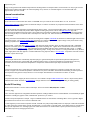
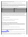
high-resolution pics of 51 II PCB.
Internal construction
mpcat.jpg mpca.jpg
As we now see, it's PCB of Fluke 50 II series, marked 5X, so it's just same for all four meter SKUs, 51, 52 , 53 and 54.
Fluke's service manual is rather useless for internals analysis, as it does not contain any component level information, leave alone
stuff like schematics or BOM list.
Lets dig into details and components found onboard. Big chip in center - Texas instruments MCU ASIC. I was lucky enough to get
REV 101 meter version, likely early board, where original TI marking was present. This is 16bit MSP430P337I chip, with
one-time-programmable firmware from Fluke. Later meters have same MCU but with Fluke markings only. Most of Fluke portable
tools are using TI chips, so no wonder here. Used chip have 16-bit cpu core, UART and SPI links, hardware 16x16 multiplier and
LCD controller.
Looking at board counterclockwise from the left we found generic amplifier LMV321M5 in SOT23-5 for LED back-light current source.
Then power supply - two National LP2980 LDOs (precision %0.5, 50mA output current , output voltage +2.8V), then DC-DC using
switching capacitor tech Linear LT1044, and 12.5MHz oscillator for CPU.
Heart of meter - sigma-delta ADC Linear LTC2400, with awesome 24-bit resolution, 4ppm tol and 0.5ppm bias with 110db SNR.
Maximum conversion speed - 6 Hz. Cost of just this chip, without anything else - approx 8$ on small amounts from Linear shop.
Near it we can opamp Linear LT1097 - low-noise high precision amplifier with 50uV offset, temperature drift 1uC per °C, CMRR
115dB, used as thermocouple voltage amplifier. Next three big chips - analog muxes, dual 4:1. I'm using similar 4051 in my Neutron
power supply tester and other projects, so familiar with them. 8-leg chip near them is TI TLC3702C - comparator, looks like used for
detection of open sensor input.
inputs.jpg
Thermocouple contacts are connected by separate springs to gold-covered pads on special board, placed to collet pins into
mainboard. All contacts are covered with gold, oxidization shall not pass. For precise temperature measurement it's also very
essential to have constant and known temperature of cold junction, where thermocouple input connected to meter.
2ch.jpg
Connector board made from 1.3mm thick pure copper substrate with thin insulation layer and parts on single side over it. This
amount of copper mass maintain temperature of all contacts very close and stable. Such board manufacturing is rather expensive,
more expensive than generic 4-6 layer board, as an for example. Nice attention to construction from Fluke, no doubt.
pcbas.jpg
Component side of this copper pcb also have two ICs, one of which is simple ATMEL AT25010AN - this is 1 Kbyte memory where
calibration data stored. And near it LT1034CS8-2.5 voltage reference from Linear Technology, according to marking (3402).
Model ID hacking
Recall to back PCB shot - we have meter mode straps. These are resistors R50, R49, R51 and R52.
resistor_id.jpg
This is common approach for configuration firmware operation, reading hardware level on resistive divider, and used widely in digital
electronics, including PC graphic cards, motherboards, processors, you name it.
General concept and operation is simple - usage of soldered resistors as fixed switch, connecting either +3.3V or ground to digital
input, which can be read as one or zero from firmware code.
For this engineers put two resistor footprints on PCB, each with one pad (usually middle) tied to one input pin of CPU/GPU/controller
etc. Other pad of one resistor tied to ground, secondresistor - to VCC power or I/O level power. If we solder resistor to ground signal then input to chip will be zero, meaning logical zero visible to firmware.I f we solder resistor to power pad, then we have power
connected to input, thus having logical one here.
18/12/2015
2/5