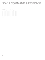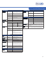
1
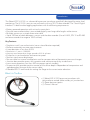
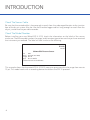
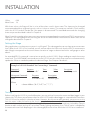
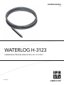
OWNERS MANUAL
V2.0
WATERLOG H-3123
SUBMERSIBLE PRESSURE SENSOR WITH SDI-12 OUTPUT
D66 0815
CONTENTS & WARRANTY
This user manual is a guide for the H-3301/3311 shaft encoder. For more information, updated
manuals, brochures, technical notes, and supporting software on the H-3301/H-3311 shaft encoder,
please refer to waterlog.com or contact your sales representative.
For additional assistance, please contact us at +1.435.753.2212 or [email protected]
WaterLOG Warranty................................................................................................ 1
Ch: 1 Introduction.................................................................................................... 2
What’s In The Box..................................................................................................... 3
Check The Sensor Cable........................................................................................ 4
Check the Model Number..................................................................................... 4
Ch: 2 Installation...................................................................................................... 5
Water Depth............................................................................................................ 6
General Installation Recommendations............................................................... 6
Stilling Wells............................................................................................................ 7
Dry Air Junction Box............................................................................................... 7
Making Connections to the H-3123........................................................................ 8
Wiring and Installation Precautions...................................................................... 9
Programming Your Data Recorder........................................................................ 9
Programming The SDI-12 Address....................................................................... 9
Programming The H-3123 Sensor........................................................................ 9
Setting the Stage..................................................................................................... 10
Testing...................................................................................................................... 10
Ch: 3 Maintenance....................................................................................................12
Changing the Desiccant......................................................................................... 13
Precautions............................................................................................................... 13
Maintaining Desiccant Packs..................................................................................13
Trouble Shooting..................................................................................................... 13
Ch: 4 SDI-12 Command & Response Protocol................................................... 14
SDI-12 Master Command List............................................................................... 16
Measure Command................................................................................................ 17
Measure Command with CRC.............................................................................. 18
Concurrent Measurement Command...................................................................19
Concurrent Measurement Command with CRC................................................. 19
Send Data Command............................................................................................ 20
Continuous Measurements.................................................................................... 21
Continuous Measurements with CRC.................................................................. 21
Send Acknowledge Command............................................................................. 22
Initiate Verify Command.........................................................................................22
Send Identification Command.............................................................................. 23
Change Sensor Address Command..................................................................... 24
Extended Set_Current_Stage Command............................................................. 24
Extended Read/Write Stage_Offset and Read/Write Stage_Slope...................25
Extended Read Mean_Count and Write Mean_Count....................................... 26
Extended “XTEST”................................................................................................... 27
Appendix................................................................................................................... 29
Contents & Warranty
“WATERLOG™ PRODUCTS MANUFACTURED BY YELLOW SPRINGS INSTRUMENTS CO., INC. are
warranted by Yellow Springs Instruments Co., Inc. (“YSI”) to be free from defects in materials and
workmanship under normal use and service for twelve (12) months from date of shipment unless
otherwise specified in the corresponding YSI pricelist or product manual.
WaterLOG™ products not manufactured, but that are re-sold by YSI, are warranted only to the
limits extended by the original manufacturer. Batteries, desiccant, and other consumables have
no warranty. YSI’s obligation under this warranty is limited to repairing or replacing (YSI’s option)
defective products,which shall be the sole and exclusive remedy under this warranty.
The customer shall assume all costs of removing, reinstalling, and shipping defective products to YSI.
YSI will return such products by surface carrier prepaid within the continental United States of America.
To all other locations, YSI will return such products best way CIP (Port of Entry) INCOTERM® 2010,
prepaid. This warranty shall not apply to any products which have been subjected to modification,
misuse, neglect, improper service, accidents of nature, or shipping damage. This warranty is in lieu
of all other warranties, expressed or implied. The warranty for installation services performed by YSI
such as programming to customer specifications, electrical connections to products manufactured by
YSI, and product specific training, is part of YSI’s product warranty. YSI EXPRESSLY DISCLAIMS AND
EXCLUDES ANY IMPLIED WARRANTIES OF MERCHANTABILITY OR FITNESS FOR A PARTICULAR
PURPOSE. YSI is not liable for any special, indirect, incidental, and/or consequential damages.”
A complete TERMS AND CONDITIONS OF SALE can be viewed at:
http://www.ysi.com/terms-and-conditions.php
1
01 /
2
INTRODUCTION
Introduction
The WaterLOG® H-3123 is a submersible pressure transducer specifically designed for water level
monitoring. The H-3123 is easy to use and works with any SDI-12 data recorder. The “Serial-Digital
Interface” is ideal for data logging applications with the following requirements.
• Battery powered operation with minimal current drain
• Pressure measurement data is transmitted digitally over long cable lengths without error
• Multiple sensors on a simple three-wire cable
• Up to 250 feet of cable between a sensor and the data recorder (Use of H-423, SDI-12 to RS-485
converter extends the range to 1000’s of feet)
Key Features
• Simple to install, use and maintain (no on-site calibration required)
• Performs extremely accurate measurements
• Linear deviation is less than 0.02%
• Resolution is 1 part in 1,000,000
• Accuracy over temperature range exceeds ±0.02 ft. of water
• Enclosure is non-conductive and corrosion proof
• Stainless steel sensor diaphragm
• Sensor cable has internal atmospheric vent for compensation of barometric pressure changes
• Junction box provides access for inspection and maintenance of dry-air desiccant
• Low current operation (less than 500 microamps typical standby)
• Suspension bail provides positive control of the sensor depth independent of temperature and
age dependent changes to the sensor cable
• Extended SDI-12 commands for setting the Stage to the current water elevation
What’s In The Box
• (1) WaterLOG H-3123 pressure transducer with
polyurethane vented cable and dry air junction box
• (3) Spare desiccant packs
• (1) Owner’s Manual
3
INTRODUCTION
Check The Sensor Cable
Be sure that the vented cable is long enough to reach from the submerged location to the junction
box of the dry air system. Also, be sure that the data logger cable is long enough to reach from the
dry air junction box to your data recorder.
Check The Model Number
Before installing your new WaterLOG H-3123, check the information on the label of the sensor
enclosure. Check the model number, the range, and the output type to be sure that you have received
the instrument you ordered. The label will look similar to the following:
H-3123
Model
Submersible Pressure Sensor
S/N1103
Range: 0-15 PSI (34.6’ H20)
Output:SDI-12
Input: 10 to 16.0 Volts
Contains No User Serviceable Parts
This example shows that the waterLOG H-3123-15 measures pressure within the range from zero to
15 psi. This model works with a recording device that follows the SDI-12 protocol.
4
02 /
INSTALLATION
5
INSTALLATION
The H-3123 submersible pressure sensor is
very versatile and can be used in many water
monitoring applications. Before proceeding
with the installation, please consider several
site preparation and maintenance issues:
Water Depth
The following chart shows the maximum depth
to which the H-3123 is factory calibrated.
The sensor can survive temporary operation
up to twice the maximum rated depth for
your model’s range. However, any pressure
measurements made beyond the rated depth
will be inaccurate. The H-3123 will be damaged
if it is placed deeper than twice the maximum
System Components
rated depth.
Note: Depth calculations are derived from the
standard equation that one PSI is generated by
a column of water 27.680 inches deep at 39.4
°F.
Model
H-3123-15
H-3123-30
Pressure Range
0 to 15 psi
0 to 30 psi
Depth Range*
0 to 34.60 ft.
0 to 69.20 ft.
Accuracy
±0.007 ft.
±0.014 ft.
General Installation Recommendations
The sensor must be located in a no flow area. Alterations in water flow can cause pressure variations.
Thus, if the sensor is subjected to open flow changes, your water level measurements will be
inconsistent. To obtain accurate and reliable data, use stilling wells, sand points, or other “no
flow” installation techniques.
The H-3123 submersible pressure transducer is not recommended for use in applications where
silt and mud are problematic. In addition, if the sensor is used in a shallow water application with
a chance to dry out with mud coating the sensor diaphragm, the diaphragm compliance will be
altered and the factory calibration spoiled.
The H-3123 sensor will be permanently damaged if it is frozen. Transducers which are installed
in geographical areas with harsh winters should be removed for the winter unless they are installed
deep enough in the water with no danger of freezing. Ice may form around the sensor cable without
causing damage or performance degradation. However, the cable should be protected to minimize
the possibility of incurring damage as the ice shifts or breaks up during times of thawing.
6
Installation
The polyurethane drop cable is suitable for immersion, direct burial and is somewhat ultraviolet (UV)
resistant. Whenever possible, precautions should be taken to protect the cable from direct sunlight,
rodents and mechanical damage.
Experience has shown that if a portion of the H-3123 housing or the sensor cable is installed above
the water and exposed to sunlight (e.g. installed in shallow water), a temperature gradient can occur
inside the enclosure and vent tube. As the air temperature changes, the air density changes. A change
in the air density inside the sensor or vent tube column causes a partial pressure on the reference
side of the sensor which will raise or lower the H-3123s pressure reading. This is a “law of physics”
problem not unique to WaterLOG Series transducers. It can be avoided by installing the transducer
in a horizontal position to ensure the entire enclosure is covered by water. Protect the sensor cable
so it remains at the temperature of the surrounding air and is not heated directly by the sun.
Stilling Wells
The H-3123 can be hung in well bores, stilling wells and
stand-pipes, and can be installed by suspending the sensor
using its polyurethane electrical cable.
When installing the H-3123 in wells or stand pipes, make
certain the surface of the water in the pipe is open to the
atmosphere. Well pipes are often capped with a sanitary well
seal or locking cap. Make certain the well cap has a suitable
hole or screened vent.
Dry Air Junction Box
The surface of the water being measured is exposed to
atmospheric pressure, therefore submersible pressure
sensors must provide correction for changes in barometric
air pressure. Several industry designs employ a sealed
sensor housing and measure the atmospheric pressure
separately. This sheme however, doubles the offset drift
because two pressure sensors are needed. To provide the
best accuracy possible, the H-3123 uses an atmospheric
referenced pressure sensor design. The pressure sensor in
the H-3123 has an internal vent tube to compensate for the
atmospheric pressure changes. This vent tube passes up
the drop cable and is open to the atmosphere at the top.
Vent tube designs however, are susceptible to moisture
condensation in the tube. As the atmospheric pressure
changes, small amounts of air flow up and down the vent
tube. Convection can also contribute to airflow within the
vent tube. If the vent tube is colder than the dew point of the
air, moisture will condensein the tube. This condition occurs
continually because the submerged portion of the vent tube
is maintained at the water temperature.
Vertical Position H-3123
7
INSTALLATION
The temperature of both surface and
ground water are normally well below the
dew point of the surrounding air.
The H-3123 dry air junction box provides
for terminating the polyurethane sensor
cable and contains desiccant to keep the
atmospheric vent tube dry. The enclosure
has a transparent lid which allows visual
inspection of the desiccant packs. The
enclosure has a small screened vent port
in the top cover which exposes the sensor
vent tube to the atmosphere.
The dry air junction box should be
installed in a protected, dry location such
as an instrument shelter. The installation
should provide easy access and facilitate
regular inspection and maintenance of the
desiccant.
Dry Air Junction Box
Making Connections to the H-3123
The H-3123 is an SDI-12 V1.3 compliant
sensor. It connects directly to any data
recorder with SDI-12 capability. The dry
air junction box has a 4-conductor pigtail
cable for making connections to your data
logger. The pigtail cable can be modified
or replaced for making connections to
your data logger. The pigtail cable can
be modified or replaced in the field. The
table below shows the proper connections
to the pigtail. The power for the H-3123
is supplied by the SDI-12 +12V input. The
connections are also shown on a wiring
diagram inside the dry air junction box.
If the polyurethane cable between the
H-3123 sensor and the dry air junction
box must be routed through a conduit or
small hole, the polyurethane cable can be
temporarily disconnected from the dry air
junction box as needed. Reconnect the
sensor cable as shown in the table on page
9.
8
Dry Air Junction Box Wiring
Data Logger Connections
Wire
Name
Red
+12Volt DC
White
SDI-12 Data
Black
Ground
Shield
Ground
Installation
Wiring and Installation Precautions
• The shield in the hook-up cable must be connected to the data logger ground.
• The data recorder must be earth grounded.
• The H-3123 requires that the water be at ground potential. Mother Nature takes care of this for surface
and ground water.
• Make certain the seals in the liquid tight cable fittings
on the dry air junction box are tight.
• Make certain the dry air junction box lid is screwed
on and sealed properly.
• Make certain the vent port on the dry air junction box
is not covered or blocked.
• Make certain the end of the vent tube inside the dry
air junction box is not plugged or blocked.
• Check the desiccant packs. Replace if necessary.
H-3123 Sensor Connections
Wire
Name
Red
+12Volt DC
White
SDI-12 Data
Black
GND
Green
Shield
Programming Your Data Recorder
You must prepare your data recorder to receive and record the H-3123 data. Since data recorders differ
widely, refer to your specific recorder manufacturer’s directions. In general, program the data recorder to
input four values via the SDI-12 port. Usually only one or two of the parameters is actually recorded. Your data
recorder must issue an “aM!” command, then collect the data with a “aD0) command, as explained in Chapter
4. The H-3123 places four parameters in its data buffer:
a+AA.AAA+BB.BBB+CC.C+DD.D<cr><If>
Where:
a
AA.AAA
BB.BBB
CC.C
DD.D
=SDI-12 address 0-9, A-Z
=Stage (feet, inches, meters, etc.)
=Pressure (PSI)
=Temperature (C)
=Sensor Supply Voltage (Volts)
Programming The SDI-12 Address
If more than one sensor is to be connected to the SDI-12 bus, make certain each sensor has a different
address. The H-3123 comes from the factory with its address set to “0”. The address can be changed with an
extended SDI-12 command (see Chapter 4).
Programming The H-3123 Sensor
The H-3123 comes from the factory with the following settings:
SDI Address: 0
Slope:
2.3067 (feet of H20)
9
INSTALLATION
Offset:0.00
MeanCount:16
With these values, the Stage will be in units of feet when used in clean water. The slope can be changed
to accommodate other engineering units such as inches or meters. The setups are stored in Flash memory
within the H-3123 and will not be lost if the power is disconnected. The extended commands for changing
these setups are described in detail in Chapter 4.
MeanCount is the number of raw pressure measurements averaged together to make one SDI-12 measurement
sequence. This setting determines how long the sensor will take to make a measurement. MeanCount can be
changed as described in Chapter 4.
Setting the Stage
Many applications use the pressure sensor in a stilling well. The submerged sensor translates pressure to water
level. When the H-3123 is first installed, you will want to adjust the Offset such that the SDI-12 measurement
data (Stage) corresponds to the current water elevation or stage as determined with a staff gauge or other
datum.
An extended SDI-12 command is convenient to quickly set the H-3123’s Stage reading to match the current
water level. The “aXSCSdd.d!” command causes the H-3123 to make a fresh measurement and automatically
update the Offset as needed to produce the desired Stage. See Chapter 4 for details.
Example of a H-3123 Extended “Set Current Stage” Command:
Command Response Time
Values
Description
“aXSCS2.3!”“a0031<cr><If>”
3sec1Set the Stage to 2.3
Subsequent Command
Response Description
“aD0”a+12.80<cr><If)
The new Offset
Where:
a
=Sensor Address (“0-9”, “A-Z”, “a-z”, “*”, “?”).
Testing
Before installing the H-3123 in your field location, you may wish to first test the sensor and data logger in your
shop or lab. This allows you to become familiar with H-3123 and the data logger in a controlled environment.
The H-3123 can be tested in a bucket of water. However, for this test to work correctly, you must run a wire
from the water inside the bucket to the chassis ground of the data recorder. The wire establishes a ground
connection between the water and the data logger. Water and other conductive objects isolated by a plastic
bucket or table surface pick up AC noise from nearby lighting and power lines. The AC noise is coupled by
the water to the stainless diaphragm in the submerged pressure sensor. While the H-3123 has a conductive
10
Installation
housing, it is electrically isolated from the rest of the circuitry to prevent galvanic corrosion from occurring.
This makes it so the circuitry is also isolated from the surrounding water. The AC noise may affect the pressure
measurement due to large voltages between the water media and the sensor (data logger) ground. This
precaution is not necessary for field installations because surface water and ground water are not isolated
from earth ground.
11
03 /
12
MAINTENANCE
Maintenance
Sustained operation of the H-3123 pressure sensor is almost maintenance free. Experience has shown that
moisture condensing in the atmospheric reference tube creates the largest percentage of field problems. The
desiccant in the H-3123 junction box dry air system should be changed on a fixed schedule, normally every
three to six months. Different areas in the world have widely varying humidity and temperature fluctuations.
Pay close attention to the desiccant condition in your particular installation. The desiccant packs contain
indicating silica gel and have a transparent window that allows the condition of the desiccant to be observed.
The silica gel has a blue color when dry and changes to pink as it absorbs moisture.
Changing the Desiccant
To change desiccant in the H-3123 junction box
dry air system:
Step 1: Remove the clear plastic lid.
Step 2: Replace the desiccant packs.
Step 3: Reinstall the clear plastic lid.
Precautions
• Make certain the seals in the liquid tight
cable fittings on the dry air junction box are
tight.
• Make certain the dry air junction box lid is
screwed on and sealed properly.
Maintaining Desiccant Packs
Dry Air Junction Box
The desiccant bags have a transparent strip which allows the condition of the desiccant to be visually checked.
The desiccant has a dark blue color when dry and changes to pink as it absorbs moisture. The desiccant packs
can be reused by drying them in an oven at 180 °F to 220 °F for 4 to 8 hours or until the desiccant returns to
a dark blue color.
Trouble Shooting
Experience over the years with submersible sensors has identified several common problems:
No SDI-12 response or intermittent data
1. 2.
3. Check all wiring including power and ground connections. Battery
connections can become corroded over time.
The H-3123 measures and reports it’s internal power supply
voltage along with Stage and Pressure. Make a measurement and
check to see if the coltage is between 10.0 to 16.0 Volts.
Check the connections between your data recorder and the
H-3123 sensor.
Data Logger Connections
Wire
Name
Red
+12Volt DC
White
SDI-12 Data
Black
Ground
Shield
Ground
Offset Drift
Check the desiccant packs. If moisture accumulates in or blocks the vent tube, changes in barometric pressure
will affect the pressure measurement. If this is the case, you should contact WaterLOG technical support for
instructions as how to proceed.
13
04 /
14
SDI-12 COMMAND &
RESPONSE PROTOCOL
SDI-12 Command & Response Protocol
This is a brief description of the Serial Digital Interface (SDI-12) Command and Response Protocol used by
the WaterLOG Series Model H-3123 sensor. Included is a description of the commands and data format
supported by the H-3123.
Refer to the document “A SERIAL DIGITAL INTERFACE STANDARD FOR HYDROLOGIC AND ENVIRONMENTAL
SENSORS”. Version 1.3 january 12, 2009 Coordinated by the SDI-12 Support Group, 135 East Center, Logan,
Utah.
During normal communication, the data recorder sends an address together with a command to the H-3123
SDI-12 sensor. The H-3123 then replies with a “response”. In the following descriptions, SDI-12 commands and
responses are enclosed in quotes. The SDI-12 address and the command/response terminators are defined
as follows:
“a”
Is the sensor address. The following ASCII Characters are valid addresses: “0-9”, “A-Z”, “a-z”, “*”, “?”. Sensors will be initially programmed at the factory with the address of “0”
for use in single sensor systems. Addresses “1 to 9” and “A to Z” or “a to z” can be used
for additional sensors connected to the same SDI-12 bus. Address “*” and “?” are “wild
card” addresses which select any sensor, regardless of its actual address.
Is the last character of a command block.
“!”
“<cr><If>”
Are carriage return (0D) hex and line feed (0A) hex characters. They are the last two
characters of a response block.
Notes:
• All commands/responses are upper-case printable ASCII characters.
• Commands must be terminated with a “!” character.
• Responses are terminated with <cr><If> characters.
• The command string must be transmitted in a contiguous block with no gaps of more than 1.66 milliseconds between characters.
To enhance the error detection capability in SDI-12 data collection systems, a variation of the Start
Measurement Commands (M!, M1!...M9!), Start Concurrent Measurement Commands (C!, C1!... C9),
and Continuous Measurement Commands (aR0!...aR9!) request that the data be returned with a 16
bit Cyclic Redundancy Check (CRC) appended to it. These commands use the existing command
letters with a C appended, namely: aMC!, aMC1!... aMC9!, aCC!, aCC1! ... aCC9!, and aRC9!. When
these commands are used, the data returned in response to the D commands, or R commands, have
a CRC code appended to it.
15
SDI-12 COMMAND & RESPONSE
SDI-12 Master Command List
Standard SDI-12 commands
Command
aM!
aMC!
aC!
aCC!
aD0! and aD1!
aV!
aI!
Description
Make Measurement
Make Measurement with CRC
Make Concurrent Measurement
Make Concurrent Measurement with CRC
Send Data
Verify Sensor
Send Identification
Extended SDI-12 commands unique to the H-3123
Command
aAn!
aXSCSddd!
aXRS!
aXWSddd!
aXRO!
aXWOddd!
aXRMC!
aXWMCddd!
aXTEST!
16
Description
Change sensor address
Set current “stage”
Read Slope
Write Slope
Read Offset
Write Offset
Read Mean_Count
Write Mean_Count
Initiate a repeating test printout
SDI-12 Command & Response Protocol
Measure Command
The Measure Command causes a measurement sequence to be performed. Data values generated in response
to this command are stored in the sensor’s buffer for subsequent collection using “D” commands. The data
will be retained in the sensor until another “M”, “C”, or “V” command is executed.
Command
Response Description
“aM!”“atttn<cr><If>”Initiate measurement
Where:
a
is the sensor address (“0-9”, “A-Z”, “a-z”, “*”, “?”)
is an upper-case ASCII character
M
ttt
is a three digit integer (000-999) specifying the maximum time, in seconds, the sensor will take
to complete the command and have measurement data available in its buffer.
n
is a single digit integer (0-9) specifying the number of values that will be placed in the data
buffer. If “n” is zero (0), no data will be available using subsequent “D” commands.
Upon completion of the measurement, a service request “a<cr><If>” is sent to the data recorder indicating
the sensor data is ready. The data recorder may wake the sensor with a break and collect the data any time
after the service request is received or the specified processing time has elapsed.
Example of a H-3123 “aM!” command:
Command Response Time
Values
Description
“aM!”“a0044<cr><If>”
4 sec4Make measurement
Subsequent Command
Response
“aD0”a+AA.AAA+BB.BBB+CC.C+DD.D<cr><If>
Where:
AA.AAA
BB.BBB
CC.C
DD.D
= Stage (feet, inches, meters, etc.)
= Pressure (PSI)
= Temperature (C)
= Sensor Supply Voltage (Volts)
17
SDI-12 COMMAND & RESPONSE
Measure Command with CRC
The Measure Command causes a measurement sequence to be performed with a CRC appended to the
data. Data values generated in response to this command are stored in the sensor’s buffer for subsequent
collection using “D” commands. The data will be retained in the sensor until another “M”, “C” or “V” command
is executed.
Command
Response Description
“aMC!”“atttn<cr><If>”Initiate measurement
Where:
a
is the sensor address (“0-9”, “A-Z”, “a-z”, “*”, “?”).
are upper-case ASCII characters
MC
ttt
is a three digit integer (000-999) specifying the maximum time, in seconds, the sensor will take
to complete the command and have measurement data available in its buffer.
n
is a single digit integer (0-9) specifying the number of values that will be placed in the data
buffer. If “n” is zero (0), no data will be available using subsequent “D” commands.
Upon completion of the measurement, a service request “a<cr><If>” is sent to the data recorder indicating
the sensor data is ready. The data recorder may wake the sensor with a break and collect the data any time
after the service request is received or the specified processing time has elapsed.
Example of a H-3123 “aM!” command:
Command Response Time
Values
Description
“aM!”“a0044<cr><If>”
4 sec4Make measurement
Subsequent Command
Response
“aD0”a+AA.AAA+BB.BBB+CC.C+DD.DXXX<cr><If>
Where:
AA.AAA
BB.BBB
CC.C
DD.D
XXX
18
= Stage (feet, inches, meters, etc.)
= Pressure (PSI)
= Temperature (C)
= Sensor Supply Voltage (Volts)
=CRC (ASCII Characters)
SDI-12 Command & Response Protocol
Concurrent Measurement Command
A concurrent measurement is one which occurs while other SDI-12 sensors on the bus are also taking
measurements. This command is similar to the “aM!” command, however, the nn field has an extra digit and
the sensor does not issue a service request when it has completed the measurement. Communicating with
other sensors will NOT abort a concurrent measurement. Data values generated in response to this command
are stored in the sensor’s buffer for subsequent collection using “D” commands. The data will be retained in
the sensor until another “M”, “C”, or “V” command is executed.
CommandResponseDescription
“aM!”“a0044<cr><If>”Make measurement
Where:
a
is the sensor address (“0-9”, “A-Z”, “a-z”, “*”, “?”).
is an upper-case ASCII character
C
ttt
nn
is a three digit integer (000-999) specifying the maximum time, in seconds, the sensor will
take to complete the command and have measurement data available in its buffer.
is a two digit integer (00-99) specifying the number of values that will be placed in the data buffer. If “n” is zero (0), no data will be available using subsequent “D” commands.
The data recorder may wake the sensor with a break and collect the data anytime after the specified processing
time has elapsed.
Example of a H-3123 “aC!” command:
Command Response Time
Values
Description
“aC!”“a0044<cr><If>”
4 sec4Make measurement
Subsequent Command
Response
“aD0”a+AA.AAA+BB.BBB+CC.C+DD.D<cr><If>
Where:
AA.AAA
BB.BBB
CC.C
DD.D
= Stage (feet, inches, meters, etc.)
= Pressure (PSI)
= Temperature (C)
= Sensor Supply Voltage (Volts)
19
SDI-12 COMMAND & RESPONSE
Concurrent Measurement Command with CRC
A Concurrent Measure with CRC Command causes a measurement sequence to be performed with a CRC
appended to the data. Data values generated in response to this command are stored in the sensor’s buffer
for subsequent collection using “D” commands. The data will be retained in the sensor until another “M”, “C”
or “V” command is executed.
CommandResponseDescription
“aCC!”“atttnn<cr><If>”Initiate measurement
Where:
a
is the sensor address (“0-9”, “A-Z”, “a-z”, “*”, “?”).
is an upper-case ASCII character
CC ttt
nn
is a three digit integer (000-999) specifying the maximum time, in seconds, the sensor will
take to complete the command and have measurement data available in its buffer.
is a two digit integer (00-99) specifying the number of values that will be placed in the data buffer. If “n” is zero (0), no data will be available using subsequent “D” commands.
The data recorder may wake the sensor with a break and collect the data anytime after the specified processing
time has elapsed.
Example of a H-3123 “aC!” command:
Command Response Time
Values
Description
“aCC!”“a0044<cr><If>”
4 sec4Make measurement
Subsequent Command
Response
“aD0”a+AA.AAA+BB.BBB+CC.C+DD.DXXX<cr><If>
Where:
AA.AAA
BB.BBB
CC.C
DD.D
XXX
= Stage (feet, inches, meters, etc.)
= Pressure (PSI)
= Temperature (C)
= Sensor Supply Voltage (Volts)
= CRC (ASCII Characters)
Send Data Command
The Send Data command returns sensor data generated as the result of previous “aM!”, “aC!”, or “aV!”
commands. Values returned will be sent in 33 characters or less. The sensor’s data buffer will not be altered
by this command.
20
SDI-12 Command & Response Protocol
CommandResponse
“aD0!”through “aD9!”
“apd.d ... pd.d<cr><If>”
Where:
a
D0...D9
is the sensor address (“0-9”, “A-Z”, “a-z”, “*”, “?”).
Is a polarity sign (+ or -)
p
are upper-case ASCII characters.
d.d
represents numberic digits before and/or after the decimal. A decimal may be used in any position in the value after the polarity sign. If a decimal is not used, it will be assumed
to be after the last digit.
For example: +3.29 +23.5 -25.45 +300
If one or more values were specified and a “aD0!” returns no data (<CR><LF> only), it means that the
measurement was aborted and a new “M” command must be sent.
Example of a H-3123 “aD0!” command:
Previous Command
Response
“aM!”“a0044<cr><If>”
Subsequent Command
Response
“aD0”a+AA.AAA+BB.BBB+CC.C+DD.D<cr><If>
Where:
AA.AAA
BB.BBB
CC.C
DD.D
= Stage (feet, inches, meters, etc.)
= Pressure (PSI)
= Temperature (C)
= Sensor Supply Voltage (Volts)
Continuous Measurements
Sensors that are able to continuously montior the phenomena to be measured, such as a cable position, do
not require a start measurement command. They can be read directly with the R commands (R0!...R9!). The R
commands work exactly like the D (D0!...D9!) commands. The only difference is that the R commands do not
need to be preceded with an M command.
The H-3123 does not support the aR0! continuous measurement command because the measurement and
math operations require several seconds to complete.
Continuous Measurements with CRC
The H-3123 does not support the aRC0! continuous measurement command because the measurement and
math operations require several seconds to complete.
21
SDI-12 COMMAND & RESPONSE
Send Acknowledge Command
The Send Acknowledge Command returns a simple status response which includes the address of the sensor.
Any measurement data in the sensor’s buffer is not disturbed.
Command Response
“a!”
“a<cr><lf>”
Where:
a
is the sensor address (“0-9”, “A-Z”, “a-z”, “*”, “?”)
Initiate Verify Command
The Verify Command causes a verify sequence to be performed. The result of this command is similar to the
“aM!” command except that the values generated are fixed test data and the results of diagnostic checksum
tests. The data generated in response to this command is placed in the sensor’s buffer for subsequent
collection using “D” commands. The data will be retained in the sensor until another “M”, “C”, or “V” command
is executed.
Command
“aV!”
Response
“atttn<cr><If>”
Description
Initiate verify sequence
Where:
a
is the sensor address (“0-9”, “A-Z”, “a-z”, “*”, “?”).
is an upper-case ASCII character.
V
ttt
is a three digit integer (000-999) specifying the maximum time, in seconds, the sensor
will take to complete the command and have data available in its buffer.
n
is a single digit integer (0-9) specifying the number of values that will be placed in the
data buffer. If “n” is zero (0), no data will be available using subsequent “D” commands.
Example of a H-3123 “aV!” command:
Command Response Time
Values
Description
“aV!”
“a0013<cr><If>”
1 sec
3
Return fixed data and
diagnostic data for
testing purposes
Subsequent Command
Response
“aD0”a+123.456+78.9+y<cr><lf>
22
Key
+123.456
+78.9
y
Description
Units
Fixed test data
Fixed test data
ROM checksum test 0=Failed, 1=Passed
SDI-12 Command & Response Protocol
Send Identification Command
The Send Identification Command responds with sensor vendor, model, and version data. Any measurement
data in the sensor’s buffer is not disturbed.
Command
“aI!”
Response
“allccccccccmmmmmmvvvxx...xx<cr><lf>”
Where:
a
is the sensor address (“0-9”, “A-Z”, “a-z”, “*”, “?”).
I
is an upper-case ASCII character.
ll
is the SDI-12 version compatibility level, e.g. version 1.2 is represented as “12”
cccccccc
is an 8 character vendor identification to be specidied by the vendor and usually in the
form of a company name or its abbreviation.
mmmmmm is a 6 character field specifying the sensor model number.
vvv
xx...xx
is a 3 character field specifying the sensor version number.
is an optional field of up to a maximum of 13 characters to be used for serial number or
other specific sensor information not relevant to operation of the data recorder.
Example of an “aI!” command:
“a12
DAA H-3123vvvS#nnnnnnVhhh<cr><lf>”
H-3123 implementation of the optional 13 character field:
s#nnnnnnVhhh
(12 bytes total)
Where:
“nnnnnn”
“hhh” is a six character sensor serial number
is a three digit sensor firmwater revision level
23
SDI-12 COMMAND & RESPONSE
Change Sensor Address Command
The Change Sensor Address Command allows the sensor address to be changed. The address is stored in
non-volatile flash memory within the sensor. The H-3123 will not respond if the command was invalid, the
address was out of range, or the flash programming operation failed.
Command
“aAn!”
Response
Description
“n<cr><lf>” Change sensor address
Where:
a
is the current (old) sensor address (“0-9”, “A-Z”, “a-z”, “*”, “?”). An ASCII “*” may be used
as a “wild card” address if the current address is unknown and only one sensor is
connected to the bus.
A
is an upper-case ASCII character.
n
is the new sensor address to be programmed (“0-9”, “A-Z”).
NOTE: To verify the new address use the “Identify Command.”
Example of an “Change Sensor Address” command:
Command
“aA2!”
Response Description
“2<cr><lf>”
Change sensor address to “2”
Extended Set_Current_Stage Command
The H-3123 processes the pressure sensor input and computes Pressure in PSI units. Stage is computed with a
Stage = m*Pressure+b equation. During installation it is convenient to quickly set the H-3123’s Stage reading
to match the current stage or elevation of the water as determined by a staff gauge or other datum. This
command causes the H-3123 to make a fresh measurement and automatically update the Offset (b) term as
needed to produce the desired Stage.
Example of a H-3123 Extended “Set Current Stage” command:
Command Response Time Values
“aXSCS2.3!” “a0031<cr><lf>”
3 sec 1
Description
Set the Stage to 2.3
Subsequent Command
Response Description
“aD0”a+12.80<cr><lf>
The new Offset
24
SDI-12 Command & Response Protocol
Extended Read/Write Stage_Offset and Read/Write Stage_Slope
The H-3123 processes the pressure sensor input and computes Pressure in PSI units. Stage is computed with
a Stage = m*Pressure+b equation. The Slope (m) and Offset (b) terms are programmable, allowing the user to
scale the reading into other engineering units. These commands allow the user to read or write (change) the
Stage_Slope and Stage_Offset terms. The slope is set to 2.3067 and the offset to 0.00 at the factory. With the
factory default (2.3067) the Stage will be in units of water depth (in feet). The new values are stored in nonvolatile memory within the sensor. Once the new Stage_Slope or Stage_Offset value is written to the memory,
a copy is sent to the sensor data buffer for verification. This data can be viewed by using a subsequent “D”
command. To verify these settings any other time, use the “XRS” or “XRO” commands. This command takes
001 seconds to complete and places 1 value in the data buffer. Use the “aD0” command to collect and view
the new slope or offset.
Command
“aXRS!”
“aXRO!”
“aXWSddd!”
“aXWOddd!”
Response Description
“a0011<cr><lf>”Read StageSlope
“a0011<cr><lf>”Read StageOffset
“a0011<cr><lf>” Write StageSlope
“a0011<cr><lf>”
Write StageOffset
Where:
a
is the sensor address (“0-9”, “A-Z”, “a-z”, “*”, “?”).
XRS
are upper case characters.
XRO
are upper case characters.
XWS
are upper case characters
XWO
are upper case characters.
ddd
is the new slope or offset value (For example: 20.0, 195)
Example of a H-3123 Extended “Read Stage_Slope” command:
Command Response Time
Values
Description
“aXRS!”“a0011<cr><lf>”
1 sec1Read StageSlope
Command ResponseDescription
“aD0!”“a+1.00<cr><lf>”StageSlope is 1.00
25
SDI-12 COMMAND & RESPONSE
Example of a H-3123 Extended “Write Stage_Slope” command:
Command Response Time
Values
Description
“aXWS1.234!”
“a0011<cr><lf>”
1 sec1Write StageSlope
Command ResponseDescription
“aD0!”“a+1.234<cr><lf>”StageSlope is 1.234
Extended Read Mean_Count and Write Mean_Count
The H-3123 makes multiple raw sensor measurements, discards the high and low values, integrates (averages)
the measurement data and computes Pressure (PSI). The number of raw sensor measurements made for each
SDI-12 measurement sequence is programmable. When measuring turbulent water, tides or other special
applications Mean_Count can be changed to increase or decrease the number of pressure measurements
made during the SDI-12 measurement sequence.
The H-3123 makes 7-1/2 pressure measurements per second (133ms/measurement). The ttt field in the SDI12 sensor response is computer by the H-3123 and indicates how much time the H-3123 will require to
complete the measurement sequence. The ttt field will automatically change if Mean_Count is changed.
The H-3123 comes from the factory with Mean_Count set to 16. The factory default ttt field is computed
internally by the H-3123 as follows:
Raw Measurements: +2.13 sec (0.133 sec/measurement X 16 measurements)
Math Overhead:
+0.3 sec
Round Upwards
+1.0
----------ttt3.0 Seconds
The “aXRMC!” and “aXWMC!” extended commands allow the number of raw sensor measurements for each
SDI-12 measurement sequence to be monitored or changed.
Once a new Mean_Count value is written, a copy is sent to the sensor data buffer for verification. This data can
be viewed by using a subsequent “D” command. To read or verify the value any other time, use the “XRMC”
command.
Command Response Description
“aXRMC!”“a0011<cr><lf>”Read Mean_Count
“aXWMCn!”“a0011<cr><lf>” Write Mean_Count
Where:
a
XRMC
26
is the sensor address (“0-9”, “A-Z”, “a-z”, “*”, “?”).
are upper case characters
SDI-12 Command & Response Protocol
XWMC
n
are upper case characters
is the number of raw measurements wanted
This command takes 001 seconds to complete and places 1 value in the data buffer. Use the “aD0” command
to collect and view the current value.
Example of a H-3123 Extended “Read Mean_Count” command:
Command Response Time
Values
Description
“aXRMC!”
“a0011<cr><lf>”
1 sec1Read Mean_Count
Command ResponseDescription
“aD0!”“a+16<cr><lf>”Count = 16
Example of a H-3123 Extended “Write Stage_Slope” command:
Command Response Time
Values
Description
“aXWMC8!”
“a0011<cr><lf>”
1 sec1Write Mean_Count
Command ResponseDescription
“aD0!”“a+8<cr><lf>”
Count = 8
Extended “XTEST”
This command is used for installation or production testing and requires the use of a H-4191 Sidekick interface
and a PC. This command causes the H-3123 to transmit unsolicited real-time data for testing purposes. The
test mode is used to help troubleshoot the installation by providing a continuous readout of pressure data.
This is not compliant with the SDI-12 specification and is not used with data loggers.
To activate the test mode, send the command “aXTEST!” from the PC. The H-3123 will enter the test mode and
make continuous measurements. The test mode is exited by sending a break or any new command on the
SDI-12 bus. It may take a few tries to exit if the command is sent at the same time data is being sent from the
H-3123. Removing power from the H-3123 also causes it to exit this mode.
Format:
SensorAdr + Stage + Pressure + Temperature + RawPressure (counts) + RawTemperature (counts)
27
SDI-12 COMMAND & RESPONSE
“XTEST” displays the following data:
0: +1.202 +3.222 +23.0 +12345 +67890
0: +1.212 +3.232 +23.0 +12345 +67890
0: +1.222 +3.342 +23.0 +12345 +67890
0: +1.232 +3.352 +23.0 +12345 +67890
0: +1.232 +3.352 +23.0 +12345 +67890
etc.
28
SDI-12 Command & Response Protocol
PERFORMANCE
Accuracy
Pressure
Pressure
Hysteresis
Linearity
Temperature
Resolution
Range
General
ENVIRONMENTAL
Less than or equal to 0.02% of full
scale output (FSO) over temperature
range
Less than 0.02% of FSO
Less than 0.02% deviation
Internal temperature ±1°C over
temperature range
Long-term
Drift is less than ± 0.10% of FSO per
Stability
year
Pressure
1 part in 1,000,000 (0.0001%)
Temperature
1 part in 1,000,000 (0.0001%)
PSI ranges: 15, 30, 50 or 100
Pressure
Depth
Accuracy
0 to 15 PSI
0 to 34.60 ft.
± 0.007 ft.
(10.54 m)
(2 mm)
0 to 30 PSI
0 to 69.20 ft.
± 0.014 ft.
(21 m)
(4 mm)
Pressure
Less than 2 times the rated pressure
Overload
Media
Liquids and gases compatible with
Compatibility
stainless steel and polyurethane.
Dry Air System Prevents moisture from condensing in the submersible pressure
transducer.
Provides compensation for changes
in atmospheric pressure without
impairing the sensor’s accuracy.
General
Operating
Temperature
0° to 40° C (non-freezing)
Compensated
Temperature
0° to 40° C
Storage
Temperatures
-10° to 75° C
MISCELLANEOUS
Accessories
H-3123-DAA
H-3123-MB
H-3123-VC
Dry Air Assembly
Media Barriers
Vented Cable (price per foot)
H-3123-H
Vented Cable Mesh Grip Hanger
H-306
Warranty
Note
Dry Air System Desiccant Pack (10/
pack)
The WaterLOG® H-3123 is warranted against defects
in materials and workmanship for one year from date
of shipment.
Specifications subject to change without prior notice
due to ongoing commitment to product testing and
improvement. LR September, 2014. (D06-03 0914)
MECHANICAL / POWER
Size
Housing
Material
Housing
Voltage Input
Power
Requirements Current
Connector
Cables
General
Cable Length
Protection
0.875 in. max W x 6.5 in. L
(22.2 mm x 165 mm)
316 L stainless steel with polyurethane vent tubing
9.6 to 16.0 volts DC
Standby: 1 mA maximum
Active: 15 mA maximum
10 ft. (3.048 m) Cable (H-3123 to
junction box): Polyurethane jacket,
vented, shielded, three-wire cable.
*Stainless steel cable not necessary.
UV vented cable sold separately.
Maximum: 1000 ft. (304.8 m)
On-board transient surge protection
1.5KVA
COMMUNICATION
SDI-12
Baud Rate
Protocol
Response Time
1200
SDI-12, V1.3
4-second measurement sequence
29
Xylem
1) The tissue in plants that brings water upward from the roots;
2) a leading global water technology company.
We’re 12,000 people unified in a common purpose: creating innovative solutions
to meet our world’s water needs. Developing new technologies that will improve
the way water is used, conserved, and re-used in the future is central to our work.
We move, treat, analyze, and return water to the environment, and we help people
use water efficiently, in their homes, buildings, factories and farms. In more than
150 countries, we have strong, long-standing relationships with customers who
know us for our powerful combination of leading product brands and applications
expertise, backed by a legacy of innovation.
For more information on how Xylem can help you, go to www.xyleminc.com
YSI Incorporated
1700/1725 Brannum Lane
Yellow Springs, Ohio, 45387, USA
Request a Quote
Tel:
Email:
Internet:
+1.435.753.2212
[email protected]
www.waterlog.com
Place an Order
Tel:
Email:
+1.937.767.7241
[email protected]
Customer Support
Tel:
+1.937.767.2772