1
Model 2520 Pulsed Laser Diode Test System
User’s Manual
A GREATER MEASURE OF CONFIDENCE
WARRANTY
Keithley Instruments, Inc. warrants this product to be free from defects in material and workmanship for a
period of 1 year from date of shipment.
Keithley Instruments, Inc. warrants the following items for 90 days from the date of shipment: probes, cables,
rechargeable batteries, diskettes, and documentation.
During the warranty period, we will, at our option, either repair or replace any product that proves to be defective.
To exercise this warranty, write or call your local Keithley representative, or contact Keithley headquarters in
Cleveland, Ohio. You will be given prompt assistance and return instructions. Send the product, transportation
prepaid, to the indicated service facility. Repairs will be made and the product returned, transportation prepaid.
Repaired or replaced products are warranted for the balance of the original warranty period, or at least 90 days.
LIMITATION OF WARRANTY
This warranty does not apply to defects resulting from product modification without Keithley’s express written
consent, or misuse of any product or part. This warranty also does not apply to fuses, software, non-rechargeable
batteries, damage from battery leakage, or problems arising from normal wear or failure to follow instructions.
THIS WARRANTY IS IN LIEU OF ALL OTHER WARRANTIES, EXPRESSED OR IMPLIED, INCLUDING ANY IMPLIED WARRANTY OF MERCHANTABILITY OR FITNESS FOR A PARTICULAR USE.
THE REMEDIES PROVIDED HEREIN ARE BUYER’S SOLE AND EXCLUSIVE REMEDIES.
NEITHER KEITHLEY INSTRUMENTS, INC. NOR ANY OF ITS EMPLOYEES SHALL BE LIABLE FOR
ANY DIRECT, INDIRECT, SPECIAL, INCIDENTAL OR CONSEQUENTIAL DAMAGES ARISING OUT OF
THE USE OF ITS INSTRUMENTS AND SOFTWARE EVEN IF KEITHLEY INSTRUMENTS, INC., HAS
BEEN ADVISED IN ADVANCE OF THE POSSIBILITY OF SUCH DAMAGES. SUCH EXCLUDED DAMAGES SHALL INCLUDE, BUT ARE NOT LIMITED TO: COSTS OF REMOVAL AND INSTALLATION,
LOSSES SUSTAINED AS THE RESULT OF INJURY TO ANY PERSON, OR DAMAGE TO PROPERTY.
Keithley Instruments, Inc.
28775 Aurora Road • Cleveland, Ohio 44139 • 440-248-0400 • Fax: 440-248-6168
1-888-KEITHLEY (534-8453) • www.keithley.com
Sales Offices:
Bergensesteenweg 709 • B-1600 Sint-Pieters-Leeuw • 02-363 00 40 • Fax: 02/363 00 64
Yuan Chen Xin Building, Room 705 • 12 Yumin Road, Dewai, Madian • Beijing 100029 • 8610-8225-1886 • Fax: 8610-8225-1892
Tietäjäntie 2 • 02130 Espoo • Phone: 09-54 75 08 10 • Fax: 09-25 10 51 00
3, allée des Garays • 91127 Palaiseau Cédex • 01-64 53 20 20 • Fax: 01-60 11 77 26
Landsberger Strasse 65 • 82110 Germering • 089/84 93 07-40 • Fax: 089/84 93 07-34
Unit 2 Commerce Park, Brunel Road • Theale • Berkshire RG7 4AB • 0118 929 7500 • Fax: 0118 929 7519
1/5 Eagles Street • Langford Town • Bangalore 560 025 • 080 212 8027 • Fax: 080 212 8005
Viale San Gimignano, 38 • 20146 Milano • 02-48 39 16 01 • Fax: 02-48 30 22 74
New Pier Takeshiba North Tower 13F • 11-1, Kaigan 1-chome • Minato-ku, Tokyo 105-0022 • 81-3-5733-7555 • Fax: 81-3-5733-7556
2FL., URI Building • 2-14 Yangjae-Dong • Seocho-Gu, Seoul 137-888 • 82-2-574-7778 • Fax: 82-2-574-7838
Postbus 559 • 4200 AN Gorinchem • 0183-635333 • Fax: 0183-630821
c/o Regus Business Centre • Frosundaviks Allé 15, 4tr • 169 70 Solna • 08-509 04 600 • Fax: 08-655 26 10
13F-3. No. 6, Lane 99 Pu-Ding Road • Hsinchu, Taiwan, R.O.C. • 886-3-572-9077• Fax: 886-3-572-9031
BELGIUM:
CHINA:
FINLAND:
FRANCE:
GERMANY:
GREAT BRITAIN:
INDIA:
ITALY:
JAPAN:
KOREA:
NETHERLANDS:
SWEDEN:
TAIWAN:
1/03
Model 2520 Pulsed Laser Diode
Test System
User’s Manual
©2001, Keithley Instruments, Inc.
All rights reserved.
Cleveland, Ohio, U.S.A.
Third Printing, March 2003
Document Number: 2520-900-01 Rev. C
Manual Print History
The print history shown below lists the printing dates of all Revisions and Addenda created
for this manual. The Revision Level letter increases alphabetically as the manual undergoes
subsequent updates. Addenda, which are released between Revisions, contain important
change information that the user should incorporate immediately into the manual. Addenda
are numbered sequentially. When a new Revision is created, all Addenda associated with the
previous Revision of the manual are incorporated into the new Revision of the manual. Each
new Revision includes a revised copy of this print history page.
Revision A (Document Number 2520-900-01)..................................................................June 2001
Revision B (Document Number 2520-900-01)..............................................................August 2001
Revision C (Document Number 2520-900-01)...............................................................March 2003
All Keithley product names are trademarks or registered trademarks of Keithley Instruments, Inc.
Other brand names are trademarks or registered trademarks of their respective holders.
Safety Precautions
The following safety precautions should be observed before using this product and any associated instrumentation. Although
some instruments and accessories would normally be used with non-hazardous voltages, there are situations where hazardous
conditions may be present.
This product is intended for use by qualified personnel who recognize shock hazards and are familiar with the safety precautions
required to avoid possible injury. Read and follow all installation, operation, and maintenance information carefully before using the product. Refer to the manual for complete product specifications.
If the product is used in a manner not specified, the protection provided by the product may be impaired.
The types of product users are:
Responsible body is the individual or group responsible for the use and maintenance of equipment, for ensuring that the equipment is operated within its specifications and operating limits, and for ensuring that operators are adequately trained.
Operators use the product for its intended function. They must be trained in electrical safety procedures and proper use of the
instrument. They must be protected from electric shock and contact with hazardous live circuits.
Maintenance personnel perform routine procedures on the product to keep it operating properly, for example, setting the line
voltage or replacing consumable materials. Maintenance procedures are described in the manual. The procedures explicitly state
if the operator may perform them. Otherwise, they should be performed only by service personnel.
Service personnel are trained to work on live circuits, and perform safe installations and repairs of products. Only properly
trained service personnel may perform installation and service procedures.
Keithley products are designed for use with electrical signals that are rated Installation Category I and Installation Category II,
as described in the International Electrotechnical Commission (IEC) Standard IEC 60664. Most measurement, control, and data
I/O signals are Installation Category I and must not be directly connected to mains voltage or to voltage sources with high transient over-voltages. Installation Category II connections require protection for high transient over-voltages often associated with
local AC mains connections. Assume all measurement, control, and data I/O connections are for connection to Category I sources unless otherwise marked or described in the Manual.
Exercise extreme caution when a shock hazard is present. Lethal voltage may be present on cable connector jacks or test fixtures.
The American National Standards Institute (ANSI) states that a shock hazard exists when voltage levels greater than 30V RMS,
42.4V peak, or 60VDC are present. A good safety practice is to expect that hazardous voltage is present in any unknown
circuit before measuring.
Operators of this product must be protected from electric shock at all times. The responsible body must ensure that operators
are prevented access and/or insulated from every connection point. In some cases, connections must be exposed to potential
human contact. Product operators in these circumstances must be trained to protect themselves from the risk of electric shock.
If the circuit is capable of operating at or above 1000 volts, no conductive part of the circuit may be exposed.
Do not connect switching cards directly to unlimited power circuits. They are intended to be used with impedance limited sources. NEVER connect switching cards directly to AC mains. When connecting sources to switching cards, install protective devices to limit fault current and voltage to the card.
Before operating an instrument, make sure the line cord is connected to a properly grounded power receptacle. Inspect the connecting cables, test leads, and jumpers for possible wear, cracks, or breaks before each use.
When installing equipment where access to the main power cord is restricted, such as rack mounting, a separate main input power disconnect device must be provided, in close proximity to the equipment and within easy reach of the operator.
For maximum safety, do not touch the product, test cables, or any other instruments while power is applied to the circuit under
test. ALWAYS remove power from the entire test system and discharge any capacitors before: connecting or disconnecting ca5/02
bles or jumpers, installing or removing switching cards, or making internal changes, such as installing or removing jumpers.
Do not touch any object that could provide a current path to the common side of the circuit under test or power line (earth) ground. Always make measurements with dry hands while standing on a dry, insulated surface capable of withstanding the voltage being measured.
The instrument and accessories must be used in accordance with its specifications and operating instructions or the safety of the
equipment may be impaired.
Do not exceed the maximum signal levels of the instruments and accessories, as defined in the specifications and operating information, and as shown on the instrument or test fixture panels, or switching card.
When fuses are used in a product, replace with same type and rating for continued protection against fire hazard.
Chassis connections must only be used as shield connections for measuring circuits, NOT as safety earth ground connections.
If you are using a test fixture, keep the lid closed while power is applied to the device under test. Safe operation requires the use
of a lid interlock.
If
The
or
!
is present, connect it to safety earth ground using the wire recommended in the user documentation.
symbol on an instrument indicates that the user should refer to the operating instructions located in the manual.
The
symbol on an instrument shows that it can source or measure 1000 volts or more, including the combined effect of
normal and common mode voltages. Use standard safety precautions to avoid personal contact with these voltages.
The WARNING heading in a manual explains dangers that might result in personal injury or death. Always read the associated
information very carefully before performing the indicated procedure.
The CAUTION heading in a manual explains hazards that could damage the instrument. Such damage may invalidate the warranty.
Instrumentation and accessories shall not be connected to humans.
Before performing any maintenance, disconnect the line cord and all test cables.
To maintain protection from electric shock and fire, replacement components in mains circuits, including the power transformer,
test leads, and input jacks, must be purchased from Keithley Instruments. Standard fuses, with applicable national safety approvals, may be used if the rating and type are the same. Other components that are not safety related may be purchased from
other suppliers as long as they are equivalent to the original component. (Note that selected parts should be purchased only
through Keithley Instruments to maintain accuracy and functionality of the product.) If you are unsure about the applicability
of a replacement component, call a Keithley Instruments office for information.
To clean an instrument, use a damp cloth or mild, water based cleaner. Clean the exterior of the instrument only. Do not apply
cleaner directly to the instrument or allow liquids to enter or spill on the instrument. Products that consist of a circuit board with
no case or chassis (e.g., data acquisition board for installation into a computer) should never require cleaning if handled according to instructions. If the board becomes contaminated and operation is affected, the board should be returned to the factory for
proper cleaning/servicing.
Table of Contents
1
Getting Started
General information ................................................................... 1-2
Warranty information .......................................................... 1-2
Contact information ............................................................ 1-2
Manual addenda .................................................................. 1-2
Specifications ...................................................................... 1-2
Safety symbols and terms ................................................... 1-2
Inspection ............................................................................ 1-3
Options and accessories ...................................................... 1-3
Signal cables and adapters ........................................... 1-3
Interface cables ............................................................ 1-4
Rack mount kits ........................................................... 1-4
Product overview ........................................................................ 1-5
Mainframe front and rear panel familiarization ......................... 1-6
Front panel summary .......................................................... 1-6
Rear panel summary ........................................................... 1-7
Testhead front and rear panel familiarization ............................. 1-9
Front panel summary .......................................................... 1-9
Rear panel summary ......................................................... 1-10
Power-up .................................................................................. 1-11
Line voltage ...................................................................... 1-11
Line power connection ...................................................... 1-11
Power-up sequence ........................................................... 1-11
System identification ......................................................... 1-12
Fuse replacement .............................................................. 1-12
Display ..................................................................................... 1-13
Display format .................................................................. 1-13
Display example ........................................................ 1-13
Display units .............................................................. 1-13
Status and error messages ................................................. 1-13
Remote display programming ........................................... 1-14
Front panel display tests .................................................... 1-14
Default settings ......................................................................... 1-14
Saving and restoring user setups ....................................... 1-14
Saving setups ............................................................. 1-14
Restoring setups ......................................................... 1-15
Power-on configuration ..................................................... 1-15
Factory default settings ..................................................... 1-15
Remote setups ................................................................... 1-17
Menus ....................................................................................... 1-17
Main menu ........................................................................ 1-18
Rules to navigate menus ................................................... 1-18
Main operation menus ....................................................... 1-19
Configuration menus ......................................................... 1-21
2
Connections
Connection precautions .............................................................. 2-2
Testhead preparation ................................................................... 2-3
Testhead mounting .............................................................. 2-3
Testhead connections ........................................................... 2-3
Signal connectors ........................................................................ 2-5
Signal connectors ................................................................ 2-5
Triax DETECTOR connectors ............................................ 2-6
CURRENT OUTPUT and VOLTAGE SENSE
connectors ...................................................................... 2-6
Interlock connections .................................................................. 2-6
Remote interlock connections ............................................. 2-6
Key interlock ....................................................................... 2-7
Laser diode test connections ....................................................... 2-7
Connecting cables ............................................................... 2-7
Typical connections ............................................................. 2-7
Equivalent circuit ................................................................. 2-8
Polarity considerations ........................................................ 2-8
Connection considerations ................................................ 2-10
3
Basic Operation
Operation overview .................................................................... 3-2
Laser diode source and measure capabilities ...................... 3-2
Laser diode source and measure ranges ....................... 3-2
Laser diode source compliance .................................... 3-3
Photodiode source and measure capabilities ....................... 3-3
Photodiode source and measure ranges ........................ 3-4
Basic circuit configuration .................................................. 3-5
Polarity ................................................................................ 3-6
Laser diode current source polarity .............................. 3-6
Laser diode voltage measurement polarity .................. 3-7
Detector measurement polarity .................................... 3-8
Voltage bias polarity ..................................................... 3-8
Configuring sources .................................................................... 3-9
Editing source values ........................................................... 3-9
Configuring laser diode source .......................................... 3-10
DC mode .................................................................... 3-10
Pulse mode ................................................................. 3-11
Setting photodiode detector source values ........................ 3-11
Configuring measurements ....................................................... 3-12
Configuring laser diode measurements ............................. 3-12
Configuring photodiode measurements ............................. 3-12
Remote source and measure configuration ............................... 3-13
Source and measure configuration commands .................. 3-13
Programming example ............................................... 3-14
4
Laser Diode Testing
Source and measure configuration menus ..................................
Front panel laser diode testing ...................................................
Test circuit configuration ....................................................
Front panel test procedure ...................................................
Step 1: Configure laser diode measurement
function ..................................................................
Step 2: Configure photodiode detector measurement
functions .................................................................
Step 3: Configure laser diode current source ...............
Step 4: Configure photodiode detector voltage bias
sources ....................................................................
Step 5: Configure math functions ................................
Step 6: Turn source outputs on and trigger readings ...
Step 7: Observe readings on the display ......................
Step 8: Turn source outputs off ....................................
Remote laser diode testing .........................................................
Laser diode test commands .................................................
Programming example .................................................
5
4-2
4-3
4-3
4-4
4-4
4-4
4-4
4-4
4-5
4-5
4-5
4-5
4-5
4-5
4-7
Source-Measure Concepts
Pulse concepts ............................................................................ 5-2
Overview ............................................................................. 5-2
Delay-pulse cycle ................................................................ 5-2
Delay phase .................................................................. 5-3
Pulse phase ................................................................... 5-3
Duty cycle .................................................................... 5-3
Front panel pulse parameters .............................................. 5-4
Fixed mode .................................................................. 5-4
Staircase sweep mode .................................................. 5-4
Remote pulse parameters .................................................... 5-6
Fixed mode .................................................................. 5-6
Staircase sweep mode .................................................. 5-6
Pulse rise and fall times ...................................................... 5-7
Sweep waveforms ...................................................................... 5-8
Staircase sweeps .................................................................. 5-8
Custom sweep ..................................................................... 5-8
Current source operating boundaries ....................................... 5-10
Limit lines ......................................................................... 5-10
Loading effects .................................................................. 5-10
Data flow .................................................................................. 5-12
Basic reading display ........................................................ 5-12
Math function display ....................................................... 5-12
Sweep data storage ............................................................ 5-12
6
Range, Filter, and Math
Range .......................................................................................... 6-2
Measurement ranges ............................................................ 6-2
Laser diode voltage ranges ........................................... 6-2
Photodiode detector current ranges .............................. 6-2
Maximum readings ...................................................... 6-3
Setting the measurement range .................................... 6-3
Source ranging ..................................................................... 6-3
Remote range programming ................................................ 6-3
Range programming example ...................................... 6-4
Filter ........................................................................................... 6-4
Averaging filter overview .................................................... 6-4
Filter configuration .............................................................. 6-5
Filter control ........................................................................ 6-5
Remote filter programming ................................................. 6-5
Filter command ............................................................ 6-5
Filter programming example ........................................ 6-6
Measurement math functions ..................................................... 6-6
Conductance ........................................................................ 6-7
Resistance ............................................................................ 6-7
Power ................................................................................... 6-7
MX + B ................................................................................ 6-7
Delta (remote only) ............................................................. 6-7
Front panel math functions .................................................. 6-8
Math configuration menu ............................................. 6-8
Programming math functions ....................................... 6-8
Remote math functions ........................................................ 6-9
Math function commands ............................................. 6-9
Math function programming example ........................ 6-10
7
Sweep Operation
Sweep types ................................................................................ 7-2
Linear staircase sweep ......................................................... 7-2
Logarithmic staircase sweep ............................................... 7-3
Custom sweep ..................................................................... 7-4
Configuring and running a sweep ............................................... 7-5
Front panel sweep operation ............................................... 7-5
Configuring a sweep ..................................................... 7-5
Performing sweeps .............................................................. 7-6
Performing a linear staircase sweep ............................. 7-6
Performing a log staircase sweep ................................. 7-7
Remote sweep operation ..................................................... 7-8
Staircase sweep commands .......................................... 7-8
Staircase sweep programming example ....................... 7-9
Custom sweep commands .......................................... 7-10
Custom sweep programming example ....................... 7-10
8
Triggering
Trigger model (front panel operation) ........................................ 8-2
Idle layer ............................................................................. 8-3
Input triggers ....................................................................... 8-3
Delay and pulse phases ....................................................... 8-3
Delay phase .................................................................. 8-3
Pulse phase ................................................................... 8-4
Filtering ........................................................................ 8-4
Sweep points ................................................................ 8-4
Counter ................................................................................ 8-4
Output trigger ...................................................................... 8-4
Bench defaults ..................................................................... 8-5
Operation summary ............................................................. 8-5
Trigger link ................................................................................. 8-5
Input trigger requirements ................................................... 8-6
Output trigger specifications ............................................... 8-6
Configuring triggering ................................................................ 8-7
CONFIGURE TRIGGER menu ......................................... 8-7
Remote triggering ...................................................................... 8-9
Trigger model (remote operation) ....................................... 8-9
Idle and initiate ................................................................... 8-9
Event detection .................................................................. 8-11
Input triggers ..................................................................... 8-11
Delay and pulse phases ..................................................... 8-12
Delay phase ................................................................ 8-12
Pulse phase ................................................................. 8-12
Filtering ...................................................................... 8-12
Sweep points .............................................................. 8-12
Counter .............................................................................. 8-12
Output trigger .................................................................... 8-13
GPIB defaults .................................................................... 8-13
Operation summary ........................................................... 8-13
Remote trigger commands ................................................ 8-13
Remote trigger example .................................................... 8-14
9
Digital I/O Port, Interlocks, and Pulse Sync Output
Digital I/O port ...........................................................................
Port configuration ................................................................
Digital output lines ......................................................
Start-of-test (SOT) line ................................................
+5V output ...................................................................
Digital output configuration ................................................
Sink operation ..............................................................
Source operation ..........................................................
9-2
9-2
9-2
9-3
9-3
9-3
9-3
9-4
Controlling digital output lines ........................................... 9-4
Front panel digital output control ................................. 9-4
Remote digital output control ...................................... 9-5
Interlocks .................................................................................... 9-5
Interlock operation .............................................................. 9-6
Interlock status indicator test sequence ............................... 9-7
Reading interlock state ........................................................ 9-7
Pulse sync output ........................................................................ 9-8
Pulse sync waveform ........................................................... 9-8
Pulse sync connections ........................................................ 9-9
10
Remote Operations
Differences: remote vs. local operation .................................... 10-2
Local-to-remote transition ................................................. 10-2
Remote-to-local transition ................................................. 10-2
Selecting an interface ............................................................... 10-2
GPIB operation ......................................................................... 10-3
GPIB standards .................................................................. 10-3
GPIB connections .............................................................. 10-4
Primary address ................................................................. 10-6
General bus commands ............................................................. 10-6
REN (remote enable) ......................................................... 10-7
IFC (interface clear) .......................................................... 10-7
LLO (local lockout) ........................................................... 10-7
GTL (go to local) ............................................................... 10-7
DCL (device clear) ............................................................ 10-7
SDC (selective device clear) .............................................. 10-8
GET (group execute trigger) ............................................. 10-8
SPE, SPD (serial polling) .................................................. 10-8
Front panel GPIB operation ...................................................... 10-8
Error and status messages ................................................. 10-8
GPIB status indicators ....................................................... 10-9
REM ........................................................................... 10-9
TALK ......................................................................... 10-9
LSTN .......................................................................... 10-9
SRQ ............................................................................ 10-9
LOCAL key ....................................................................... 10-9
Programming syntax ............................................................... 10-10
Command words ............................................................. 10-10
Commands and command parameters ..................... 10-10
Query commands ............................................................. 10-12
Case sensitivity ................................................................ 10-12
Long-form and short-form versions ................................ 10-12
Short-form rules .............................................................. 10-13
Program messages ...........................................................
Single command messages ......................................
Multiple command messages ...................................
Command path rules ................................................
Using common and SCPI commands in the same
message ..............................................................
Program message terminator (PMT) .......................
Command execution rules .......................................
Response messages .........................................................
Sending a response message ....................................
Multiple response messages ....................................
Response message terminator (RMT) .....................
Message exchange protocol ............................................
RS-232 interface operation ....................................................
Sending and receiving data .............................................
Baud rate .........................................................................
Data bits and parity .........................................................
Terminator .......................................................................
Flow control (signal handshaking) ..................................
RS-232 connections ........................................................
Error messages ................................................................
Programming example ....................................................
11
10-13
10-13
10-14
10-14
10-15
10-15
10-15
10-15
10-15
10-15
10-16
10-16
10-16
10-16
10-16
10-17
10-17
10-17
10-18
10-20
10-20
Status Structure
Overview .................................................................................. 11-2
Status byte and SRQ ......................................................... 11-2
Status register sets ............................................................. 11-2
Queues ............................................................................... 11-2
Clearing registers and queues ................................................... 11-4
Programming and reading registers ......................................... 11-5
Programming enable registers ........................................... 11-5
Reading registers ............................................................... 11-6
Status byte and service request (SRQ) ..................................... 11-7
Status byte register ............................................................ 11-8
Service request enable register .......................................... 11-8
Serial polling and SRQ ..................................................... 11-9
SPE, SPD (serial polling) .......................................... 11-9
Status byte and service request commands ..................... 11-10
Programming example - set MSS (B6) when
error occurs ........................................................ 11-10
Status register sets .................................................................. 11-11
Register bit descriptions .................................................. 11-11
Standard event register ............................................. 11-11
Operation event register ........................................... 11-13
Measurement event register ..................................... 11-14
Questionable event register ...................................... 11-16
Condition registers .......................................................... 11-17
Event registers ................................................................. 11-17
Event enable registers ...................................................... 11-18
Programming example - program and read
register set ........................................................... 11-19
Queues .................................................................................... 11-19
Output queue ................................................................... 11-19
Error queue ...................................................................... 11-20
Programming example - read error queue ................ 11-21
12
Common Commands
Command summary .................................................................. 12-2
Command reference .................................................................. 12-3
*IDN? — identification query............................................ 12-3
*OPC — operation complete ............................................. 12-3
*OPC? — operation complete query ................................. 12-3
*OPC programming example ..................................... 12-4
*OPT? — option query ...................................................... 12-4
*SAV <NRf> — save ......................................................... 12-4
*RCL <NRf> — recall....................................................... 12-4
*SAV, *RCL programming example .......................... 12-5
*RST — reset ..................................................................... 12-5
*TRG — trigger ................................................................. 12-5
*TRG programming example .................................... 12-5
*TST? — self-test query .................................................... 12-6
*WAI — wait-to-continue .................................................. 12-6
13
SCPI Signal-Oriented Measurement Commands
Command summary .................................................................. 13-2
Acquiring readings ................................................................... 13-2
FETCh? ............................................................................. 13-2
[:SENSe[1]]:DATA[:LATest]? ........................................... 13-3
[:SENSe2]:DATA[:LATest]? ............................................. 13-3
[:SENSe3]:DATA[:LATest]? ............................................. 13-3
READ? .............................................................................. 13-3
MEASure? ......................................................................... 13-3
14
SCPI Command Reference
Reference tables ........................................................................ 14-2
Calculate subsystems .............................................................. 14-14
Select laser diode math function ..................................... 14-15
FORMat <name> ..................................................... 14-15
Set MX + B parameters ................................................... 14-15
MBFactor <n> .......................................................... 14-15
MMFactor <n> ......................................................... 14-15
UNITs <name> ........................................................ 14-16
Enable and read math function result ..............................
STATe <b> ...............................................................
DATA? .....................................................................
LATest? ....................................................................
DISPlay subsystem ................................................................
Control display ................................................................
ENABle <b> ............................................................
ATTRibutes? ............................................................
Read display ....................................................................
DATA? .....................................................................
Define :TEXT messages .................................................
DATA <a> ................................................................
STATe <b> ...............................................................
FORMat subsystem ................................................................
Data format .....................................................................
[:DATA] <type>[,length] .........................................
Data elements ..................................................................
ELEMents <item list> .............................................
Calculate data elements ...................................................
CALCulate <item list> ............................................
TRACe data elements .....................................................
TRACe <item list> ...................................................
SOURce4 <name> ...................................................
Byte order ........................................................................
BORDer <name> .....................................................
Status register format ......................................................
SREGister <name> ..................................................
OUTPut subsystem ................................................................
Turn sources on or off .....................................................
[:STATe] <b> ...........................................................
Interlock status ................................................................
TRIPped? .................................................................
SENSe subsystem ..................................................................
Select laser diode voltage measurement range ...............
[:UPPer] <n> ............................................................
Select detector current measurement range ....................
[:UPPer] <n> ............................................................
Select polarity .................................................................
POLarity <name> ....................................................
Query voltage limit .........................................................
TRIPped? .................................................................
Query latest readings .......................................................
[:LATest]? ................................................................
Configure and control filter .............................................
COUNt <n> .............................................................
[:STATe] <b> ...........................................................
14-16
14-16
14-17
14-17
14-17
14-17
14-17
14-18
14-18
14-18
14-18
14-18
14-19
14-19
14-19
14-19
14-22
14-22
14-23
14-23
14-24
14-24
14-25
14-25
14-25
14-26
14-26
14-27
14-27
14-27
14-27
14-27
14-27
14-28
14-28
14-28
14-28
14-29
14-29
14-29
14-29
14-30
14-30
14-30
14-30
14-31
Abort sweep ..................................................................... 14-31
:CABort[:LEVel] <n> .............................................. 14-31
:CABort:STATe <b> ................................................. 14-31
SOURce subsystem ................................................................ 14-32
SOURce[1] ...................................................................... 14-32
Control source outputs on-off .......................................... 14-32
[:IMMediate] ............................................................ 14-32
Select sourcing mode ...................................................... 14-32
MODE <name> ........................................................ 14-32
Select source function ..................................................... 14-33
FUNCtion[:SHAPe] <name> ................................... 14-33
Select source range .......................................................... 14-33
RANGe <n> ............................................................. 14-33
Set amplitudes ................................................................. 14-34
[:IMMediate][:AMPLitude] <n> .............................. 14-34
LOW <n> ................................................................. 14-34
Set voltage limit ............................................................... 14-35
PROTection[:LEVel] <NRf> .................................... 14-35
Select source polarity ...................................................... 14-35
POLarity <name> ..................................................... 14-35
Set pulse times ................................................................. 14-36
DELay <n> ............................................................... 14-36
WIDTh <n> .............................................................. 14-36
TRANsition[:STATe] <b> ........................................ 14-36
Configure sweeps ............................................................ 14-37
SPACing <name> ..................................................... 14-37
STARt <n> ............................................................... 14-37
STOP <n> ................................................................ 14-37
CENTer <n> ............................................................. 14-38
SPAN <n> ................................................................ 14-38
STEP <n> ................................................................. 14-39
POINts <n> .............................................................. 14-40
DIRection <name> ................................................... 14-40
Configure list ................................................................... 14-41
CURRent <NRf list> ................................................ 14-41
APPend <NRf list> .................................................. 14-41
POINts? .................................................................... 14-42
WIDTh <NRf list> ................................................... 14-42
APPend <NRf list> .................................................. 14-42
POINts? .................................................................... 14-42
DELay <NRf list> .................................................... 14-43
APPend <NRf list> .................................................. 14-43
POINts? .................................................................... 14-43
Sweep and list program examples ...................................
Linear staircase sweep .............................................
List sweep ................................................................
Logarithmic staircase sweep ....................................
SOURce2 and SOURce3 ................................................
Set amplitudes .................................................................
[:IMMediate][:AMPLitude] <n> .............................
SOURce4 ........................................................................
Setting digital output .......................................................
[:LEVel] <NRf> | <NDN> .......................................
Setting bit size .................................................................
BSIZe <n> ...............................................................
STATus subsystem .................................................................
Read event registers ........................................................
[:EVENt]? ................................................................
Program event enable registers .......................................
ENABle <NDN> or <NRf> .....................................
Read condition registers ..................................................
CONDition? .............................................................
Select default conditions .................................................
PRESet .....................................................................
Error queue ......................................................................
[:NEXT]? .................................................................
CLEar .......................................................................
ENABle <list> .........................................................
DISable <list> ..........................................................
SYSTem subsystem ................................................................
Default conditions ...........................................................
PRESet .....................................................................
POSetup ...................................................................
Error queue ......................................................................
[:NEXT]? .................................................................
ALL? ........................................................................
COUNt? ...................................................................
CODE[:NEXT]? ......................................................
CODE:ALL? ............................................................
CLEar .......................................................................
Simulate key presses .......................................................
KEY .........................................................................
Read version of SCPI standard .......................................
VERSion? ................................................................
RS-232 interface .............................................................
LOCal ......................................................................
REMote ....................................................................
RWLock ...................................................................
14-44
14-44
14-44
14-45
14-46
14-47
14-47
14-47
14-47
14-47
14-48
14-48
14-49
14-49
14-49
14-49
14-49
14-50
14-50
14-50
14-50
14-50
14-50
14-50
14-51
14-51
14-51
14-51
14-51
14-52
14-52
14-52
14-52
14-53
14-53
14-53
14-53
14-53
14-53
14-54
14-54
14-55
14-55
14-55
14-55
Reset timestamp .............................................................. 14-55
RESet ....................................................................... 14-55
TRACe subsystem .................................................................. 14-56
Read sample buffer .......................................................... 14-56
DATA? ...................................................................... 14-56
VALue? [<NRf>] ..................................................... 14-56
Configure sample buffer .................................................. 14-57
POINts <n> .............................................................. 14-57
Trigger subsystem ................................................................... 14-57
Initiate source/measure cycle .......................................... 14-57
INITiate .................................................................... 14-57
Abort source/measure cycle ............................................ 14-58
ABORt ..................................................................... 14-58
Program trigger model .................................................... 14-58
COUNt <n> .............................................................. 14-58
SOURce <name> ..................................................... 14-58
TIMer <n> ................................................................ 14-59
ILINe <NRf> ............................................................ 14-60
OLINe <NRf> .......................................................... 14-60
OUTPut <name> ...................................................... 14-60
A
Specifications
B
Status and Error Messages
Introduction ...............................................................................
Status and error messages ..........................................................
Eliminating common SCPI errors .............................................
-113, "Undefined header" ...................................................
-410, "Query INTERRUPTED" .........................................
-420, "Query UNTERMINATED" .....................................
C
B-2
B-2
B-7
B-7
B-7
B-8
Data Flow
Introduction ...............................................................................
Buffers ................................................................................
SENS1, SENS2, and SENS3 ..............................................
INIT ....................................................................................
FETCh? ..............................................................................
READ? and MEASure? .....................................................
CALCulate1:DATA?, CALCulate2:DATA?,
CALCulate3:DATA? .....................................................
CALCulate4:DATA? ..........................................................
TRACe:DATA? and TRACe:DATA:VALue? .....................
C-2
C-2
C-3
C-3
C-3
C-4
C-4
C-4
C-4
D
IEEE-488 Bus Overview
Introduction ............................................................................... D-2
Bus description .......................................................................... D-2
Bus lines .................................................................................... D-5
Data lines ........................................................................... D-5
Bus management lines ....................................................... D-5
Handshake lines ................................................................. D-5
Bus commands .......................................................................... D-7
Uniline commands ............................................................. D-8
Universal multiline commands .......................................... D-8
Addressed multiline commands ......................................... D-9
Address commands ............................................................ D-9
Unaddress commands ........................................................ D-9
Common commands ........................................................ D-10
SCPI commands ............................................................... D-10
Command codes ............................................................... D-10
Typical command sequences ............................................ D-12
IEEE command groups .................................................... D-13
Interface function codes .......................................................... D-14
E
IEEE-488 and SCPI Conformance Information
Introduction ................................................................................ E-2
F
Measurement Considerations
Optimizing laser diode connections ........................................... F-2
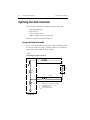
Current pulse output circuit model ..................................... F-2
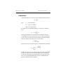
Cable inductance ................................................................. F-3
Increasing cable length ....................................................... F-5
Exposed loop area ............................................................... F-6
Sense lead connections ....................................................... F-8
Magnetic coupling ............................................................ F-10
Increasing laser diode pulse measurement speed ..................... F-11
Overview ........................................................................... F-11
Laser diode impedance matching ...................................... F-12
Model 2520 output circuit model ...................................... F-13
Transmission line model ................................................... F-14
Forward voltage measurement .......................................... F-15
Photodiode current measurement channels ....................... F-16
Noise and source impedance .................................................... F-17
DUT resistance .................................................................. F-17
Source capacitance ............................................................ F-18
Generated currents ................................................................... F-18
Offset currents ................................................................... F-19
Dielectric absorption ......................................................... F-19
Voltage burden .......................................................................... F-20
General measurement considerations ....................................... F-20
Ground loops ....................................................................
Light .................................................................................
Electrostatic interference ..................................................
Magnetic fields .................................................................
Electromagnetic Interference (EMI) ................................
G
F-20
F-21
F-22
F-22
F-23
GPIB 488.1 Protocol
Introduction ............................................................................... G-2
Selecting the 488.1 protocol ...................................................... G-2
Protocol differences ................................................................... G-3
Message exchange protocol (MEP) .................................... G-3
Using SCPI-based programs .............................................. G-3
Bus hold-off ........................................................................ G-4
Trigger-on-talk ................................................................... G-4
Message available ............................................................... G-4
General operation notes ...................................................... G-4
H
Example Programs
Introduction ............................................................................... H-2
Hardware requirements ...................................................... H-2
Software requirements ........................................................ H-2
General program instructions ............................................. H-2
Laser diode test program ........................................................... H-3
Linear staircase sweep program ................................................ H-4
List sweep program ................................................................... H-5
I
Continuous Pulse Mode
Continuous pulse mode ..............................................................
Pulse test advantage .............................................................
Duty cycle ............................................................................
Configuring the 2520 to use Continuous Pulse Mode .........
Front panel ...................................................................
Remote configuration over GPIB/IEEE-488 .......................
Related modes .....................................................................
I-2
I-2
I-2
I-3
I-3
I-4
I-4
List of Illustrations
1
Getting Started
Figure 1-1
Figure 1-2
Figure 1-3
Figure 1-4
Mainframe front panel ........................................................... 1-6
Mainframe rear panel ............................................................. 1-8
Testhead front panel ............................................................... 1-9
Testhead rear panel .............................................................. 1-10
2
Connections
Figure 2-1
Figure 2-2
Figure 2-3
Figure 2-4
Figure 2-5
Figure 2-6
Testhead connections .............................................................
Testhead signal connectors ....................................................
DETECTOR connector terminals ..........................................
Remote interlock connections ................................................
Laser diode test connections ..................................................
Equivalent circuit of laser diode test connections ..................
3
Basic Operation
Figure 3-1
Figure 3-2
Figure 3-3
Figure 3-4
Basic circuit configuration .....................................................
Laser diode current source polarity .......................................
Laser diode measure polarity .................................................
Detector current measurement polarity ..................................
4
Laser Diode Testing
Figure 4-1
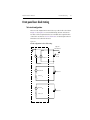
Circuit configuration for laser diode testing .......................... 4-3
5
Source-Measure Concepts
Figure 5-1
Figure 5-2
Figure 5-3
Figure 5-4
Figure 5-5
Figure 5-6
Figure 5-7
Figure 5-8
Figure 5-9
Figure 5-10
Figure 5-11
Figure 5-12
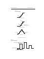
Delay-pulse cycle ................................................................... 5-2
Front panel fixed mode pulse parameters .............................. 5-4
Front panel staircase sweep mode pulse parameters ............. 5-5
Front panel staircase sweep mode DC parameters ................ 5-5
Remote fixed mode pulse parameters .................................... 5-6
Remote staircase sweep mode pulse parameters ................... 5-7
Pulse characteristics ............................................................... 5-7
Sweep waveform types .......................................................... 5-9
Custom sweep waveform ....................................................... 5-9
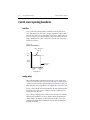
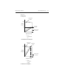
Current source limit lines ..................................................... 5-10
Loading effects .................................................................... 5-11
Data flow-front panel ........................................................... 5-13
6
Range, Filter, and Math
Figure 6-1
Averaging filter during sweep ................................................ 6-5
2-4
2-5
2-6
2-7
2-8
2-9
3-5
3-6
3-7
3-8
7
Sweep Operation
Figure 7-1
Figure 7-2
Figure 7-3
Figure 7-4
Linear staircase sweep ............................................................ 7-2
Logarithmic staircase sweep .................................................. 7-3
Custom pulse sweep ............................................................... 7-4
Sweep configuration menu tree .............................................. 7-5
8
Triggering
Figure 8-1
Figure 8-2
Figure 8-3
Figure 8-4
Figure 8-5
Figure 8-6
Trigger model (front panel operation) .................................... 8-2
Rear panel pinout ................................................................... 8-5
Trigger link input pulse specifications ................................... 8-6
Trigger link output pulse specifications ................................. 8-6
Configure trigger menu tree ................................................... 8-8
Trigger model (remote operation) ........................................ 8-10
9
Digital I/O Port, Interlocks, and Pulse Sync Output
Figure 9-1
Figure 9-2
Figure 9-3
Figure 9-4
Figure 9-5
Figure 9-6
Digital I/O port ....................................................................... 9-2
Sink operation ........................................................................ 9-3
Source operation ..................................................................... 9-4
Interlock operation ................................................................. 9-6
Pulse sync output waveform ................................................... 9-8
Pulse sync out connections ..................................................... 9-9
10
Remote Operations
Figure 10-1
Figure 10-2
Figure 10-3
Figure 10-4
IEEE-488 connector ............................................................. 10-4
IEEE-488 multi-unit test system connections ...................... 10-4
IEEE-488 and RS-232 connector location ........................... 10-5
RS-232 interface connector ................................................ 10-18
11
Status Structure
Figure 11-1
Figure 11-2
Figure 11-3
Figure 11-4
Figure 11-5
Figure 11-6
Figure 11-7
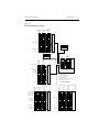
Model 2520 status register structure .................................... 11-3
16-bit status register ............................................................. 11-5
Status byte and service request (SRQ) ................................. 11-7
Standard event status .......................................................... 11-12
Operation event status ........................................................ 11-13
Measurement event status .................................................. 11-15
Questionable event status ................................................... 11-16
14
SCPI Command Reference
Figure 14-1
Figure 14-2
ASCII data format .............................................................. 14-20
IEEE-754 single precision data format (32 data bits) ........ 14-21
C
Data Flow
Figure C-1
Data flow block diagram ....................................................... C-2
D
IEEE-488 Bus Overview
Figure D-1
Figure D-2
Figure D-3
IEEE-488 bus configuration .................................................. D-4
IEEE-488 handshake sequence ............................................. D-6
Command codes .................................................................. D-11
F
Measurement Considerations
Figure F-1
Figure F-2
Figure F-3
Figure F-4
Figure F-5
Figure F-6
Figure F-7
Figure F-8
Model 2520 pulse output circuit model ................................. F-2
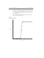
Rise time of 4A current pulse ................................................ F-4
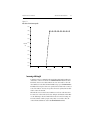
Rise time of 0.45A current pulse ........................................... F-5
Effects of open loop area ....................................................... F-6
Ideal response of 2A pulse using 10 inch cables ................... F-7
Response of 2A pulse with two square inch loop .................. F-7
Sense lead connections .......................................................... F-8
Response of 2A pulse with sense leads 1/4 inch away
from DUT ........................................................................... F-9
Magnetic coupling ............................................................... F-10
Optical pulse propagation through differing indices of
refraction ........................................................................... F-11
Model 2520 output circuit model ......................................... F-13
Minimal impedance mismatch ............................................. F-14
Compromised shield provides laser diode access ................ F-14
Voltage measurement circuit model ..................................... F-15
Pulse source and forward voltage cable interconnections ... F-15
Model 2520 photo current measurement channels with
dual bias supplies .............................................................. F-16
Voltage burden ..................................................................... F-20
Eliminating ground loops .................................................... F-21
Power line ground loops ...................................................... F-21
Figure F-9
Figure F-10
Figure F-11
Figure F-12
Figure F-13
Figure F-14
Figure F-15
Figure F-16
Figure F-17
Figure F-18
Figure F-19
List of Tables
1
Getting Started
Table 1-1
Table 1-2
Table 1-3
Table 1-4
Table 1-5
Table 1-6
Table 1-7
Table 1-8
Table 1-9
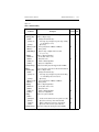
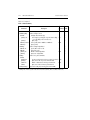
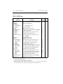
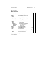
Line fuse ............................................................................... 1-12
Basic display command ........................................................ 1-14
Factory default settings ........................................................ 1-16
Main menu ........................................................................... 1-18
COMM, SETUP, and DIG OUT menus ............................... 1-20
PW, DELAY, and COMPL menus ........................................ 1-21
LASER and DETECTOR configuration menus ................... 1-22
TRIG and FILTER configuration menus .............................. 1-23
SWEEP and MATH configuration menus ............................ 1-24
3
Basic Operation
Table 3-1
Table 3-2
Table 3-3
Table 3-4
Table 3-5
Laser diode current source ranges .......................................... 3-2
Laser diode voltage measurement ranges ............................... 3-3
Photodiode current measurement ranges ............................... 3-4
Source and measure configuration commands ..................... 3-13
Basic source and measure configuration example ................ 3-14
4
Laser Diode Testing
Table 4-1
Table 4-2
Table 4-3
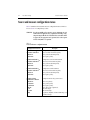
Source and measure configuration menus .............................. 4-2
Laser diode test commands .................................................... 4-6
Basic laser diode test command sequence ............................. 4-8
6
Range, Filter, and Math
Table 6-1
Table 6-2
Table 6-3
Table 6-4
Table 6-5
Table 6-6
Table 6-7
Table 6-8
Table 6-9
Table 6-10
Laser diode voltage measurement ranges ............................... 6-2
Photodiode current measurement ranges ............................... 6-2
Laser diode current source ranges .......................................... 6-3
Range commands ................................................................... 6-3
Range programming example ................................................ 6-4
Filter commands ..................................................................... 6-6
Filter programming example .................................................. 6-6
Math configuration menu ....................................................... 6-8
Math function commands ....................................................... 6-9
Math function programming example .................................. 6-10
7
Sweep Operation
Table 7-1
Table 7-2
Table 7-3
Table 7-4
Table 7-5
Logarithmic sweep points ...................................................... 7-4
Linear and log staircase sweep commands ............................ 7-8
Linear staircase sweep programming example ...................... 7-9
Custom sweep commands .................................................... 7-10
Custom sweep programming example ................................. 7-11
8
Triggering
Table 8-1
Table 8-2
Remote trigger commands ................................................... 8-14
Remote triggering example .................................................. 8-14
9
Digital I/O Port, Interlocks, and Pulse Sync Output
Table 9-1
Digital output line settings ..................................................... 9-5
10
Remote Operations
Table 10-1
Table 10-2
Table 10-3
General bus commands ........................................................ 10-6
RS-232 connector pinout ................................................... 10-19
PC serial port pinout .......................................................... 10-19
11
Status Structure
Table 11-1
Table 11-4
Table 11-5
Table 11-6
Table 11-7
Table 11-8
Table 11-9
Common and SCPI commands to reset registers and
clear queues ....................................................................... 11-4
Data format commands for reading status registers ............. 11-7
Status byte and service request enable register
commands ....................................................................... 11-10
Status byte programming example .................................... 11-10
Condition register commands ............................................ 11-17
Event register commands ................................................... 11-17
Event enable registers commands ...................................... 11-18
Program and read register programming example ............. 11-19
Error queue commands ...................................................... 11-21
12
Common Commands
Table 12-1
Table 12-2
Table 12-3
Table 12-4
IEEE-488.2 common commands and queries ......................
*OPC programming example ..............................................
*SAV, *RCL programming example ...................................
*TRG programming example ..............................................
13
SCPI Signal-Oriented Measurement Commands
Table 13-1
Signal-oriented measurement command summary .............. 13-2
14
SCPI Command Reference
Table 14-1
Table 14-2
Table 14-3
Table 14-4
Table 14-5
Table 14-6
Table 14-7
CALCulate command summary .......................................... 14-3
DISPlay command summary ............................................... 14-5
FORMat command summary ............................................... 14-6
OUTPut command summary ............................................... 14-6
SENSe command summary ................................................. 14-7
SOURce command summary ............................................... 14-9
STATus command summary .............................................. 14-12
Table 11-2
Table 11-3
12-2
12-4
12-5
12-6
Table 14-8
Table 14-9
Table 14-10
SYSTem command summary ............................................. 14-13
TRACe command summary ............................................... 14-13
TRIGger command summary ............................................. 14-14
B
Status and Error Messages
Table B-1
Status and error messages ..................................................... B-3
D
IEEE-488 Bus Overview
Table D-1
Table D-2
Table D-3
Table D-4
Table D-5
Table D-6
IEEE-488 bus command summary ........................................ D-7
Hexadecimal and decimal command codes ........................ D-10
Typical addressed multiline command sequence ................ D-12
Typical addressed common command sequence ................. D-12
IEEE command groups ....................................................... D-13
Model 2520 interface function codes .................................. D-14
E
IEEE-488 and SCPI Conformance Information
Table E-1
Table E-2
IEEE-488 documentation requirements ................................ E-3
Coupled commands ............................................................... E-4
F
Measurement Considerations
Table F-1
Minimum recommended source resistance values .............. F-17
1
Getting Started
•
General information — Covers general information that includes warranty information, contact information, safety symbols and terms, inspection, and available
options and accessories.
•
Product overview — Summarizes the features of the Model 2520 Pulsed Laser
Diode Test System.
•
Familiarization — Summarizes the controls and connectors on the unit.
•
Power-up — Covers line power connection, line voltage settings, fuse replacement, and the power-up sequence.
•
Display — Provides information about the Model 2520 display.
•
Default settings — Covers factory default setups and saving and recalling user setups.
•
Menus — Covers the main and configuration menus as well as rules to navigate
menus.
1-2
Getting Started
Model 2520 User’s Manual
General information
Warranty information
Warranty information is located at the front of this manual. Should your Model 2520
require warranty service, contact the Keithley representative or authorized repair facility
in your area for further information. When returning the instrument for repair, be sure to
fill out and include the service form at the back of this manual to provide the repair facility
with the necessary information.
Contact information
Worldwide phone numbers are listed at the front of this manual. If you have any questions,
please contact your local Keithley representative or call one of our Application Engineers
at 1-800-348-3735 (U.S. and Canada only). Additional information may be obtained at
www.keithley.com.
Manual addenda
Any improvements or changes concerning the instrument or manual will be explained in
an addendum included with the manual. Be sure to note these changes and incorporate
them into the manual.
Specifications
Model 2520 specifications shown throughout the body of this manual and the detailed
specifications listed in Appendix A were current at the time of printing, but they are subject to change without notice. For the most recent specifications, refer to the web site at
www.keithley.com.
Safety symbols and terms
The following symbols and terms may be found on the instrument or used in this manual.
The ! symbol on an instrument indicates that the user should refer to the operating
instructions located in the manual.
The
symbol on the instrument shows that high voltage may be present on the terminal(s). Use standard safety precautions to avoid personal contact with these voltages.
The WARNING heading used in this manual explains dangers that might result in personal injury or death. Always read the associated information very carefully before performing the indicated procedure.
The CAUTION heading used in this manual explains hazards that could damage the
instrument. Such damage may invalidate the warranty.
Model 2520 User’s Manual
Getting Started
1-3
Inspection
The Model 2520 was carefully inspected electrically and mechanically before shipment.
After unpacking all items from the shipping carton, check for any obvious signs of physical damage that may have occurred during transit. (There may be a protective film over the
display lens, which can be removed.) Report any damage to the shipping agent immediately. Save the original packing carton for possible future shipment. The following items
are included with every Model 2520 order:
•
•
•
•
•
•
•
•
Model 2520 mainframe with line cord.
Model 2520 testhead with two connecting cables.
Two triax connecting cables for detector signal connections.
Four unterminated 15Ω BNC coaxial connecting cables for laser diode signal
connections.
Accessories as ordered.
Certificate of calibration.
User’s Manual.
Manual addenda, containing any improvements or changes to the instrument or
manual.
If an additional user’s manual is required, order the appropriate manual package (for
example, 2520-900-00). The manual packages include a manual and any pertinent
addenda.
Options and accessories
The following options and accessories are available from Keithley for use with the
Model 2520.
Signal cables and adapters
CA-289-1A Cable — This 1m low-noise triax cable is terminated at one end with a 3-slot
male triax connector and is unterminated on the other end.
CA-290-1A Cable — This 1m BNC cable is terminated at one end with a male BNC connector and is unterminated on the other end.
Model 7078-TRX Triax Cables — These low-noise triax cables are terminated at both
ends with 3-slot male triax connectors. The Model 7078-TRX is available in 0.3m (1ft),
0.9m (3ft), 1.5m (5ft), and 3m (10ft) lengths.
Model 7078-TRX-BNC Adapter — This is a 3-slot male triax to female BNC adapter.
This adapter lets you connect a BNC cable to the triax detector inputs of the Model 2520
testhead.
Model 237-TRX-TBC Connector — This is a 3-lug female triax bulkhead connector
with cap for assembly of custom panels and interface connections.
1-4
Getting Started
Model 2520 User’s Manual
Interface cables
Models 7007-1 and 7007-2 shielded GPIB cables — Connect the Model 2520 to the
GPIB bus using shielded cables and connectors to reduce Electromagnetic Interference
(EMI). The Model 7007-1 is 1m long; the Model 7007-2 is 2m long.
Model 7009-5 shielded RS-232 cable — Connect the Model 2520 to computer serial port
using shielded cables and connectors to reduce EMI.
Models 8501-1 and 8501-2 trigger link cables — Connect the Model 2520 to other
instruments with Trigger Link connectors (e.g., Model 7001 Switch System). The Model
8501-1 is 1m long; the Model 8501-2 is 2m long.
Model 8502 trigger link adapter — Lets you connect any of the six Trigger Link lines of
the Model 2520 to instruments that use the standard BNC trigger connectors.
Model 8503 DIN to BNC trigger cable — Lets you connect Trigger Link lines one (Voltmeter Complete) and two (External Trigger) of the Model 2520 to instruments that use
BNC trigger connectors. The Model 8503 is 1m long.
Rack mount kits
Model 4288-1 single fixed rack mount kit — Mounts a single Model 2520 in a standard
19-inch rack.
Model 4288-2 side-by-side rack mount kit — Mounts two instruments (Models 182,
428, 486, 487, 2000, 2001, 2002, 2010, 2015, 2016, 2400, 2410, 2420, 2430, 2500, 2510,
2520, 6430, 6517, 7001) side-by-side in a standard 19-inch rack.
Model 4288-3 side-by-side rack mount kit — Mounts a Model 2520 and a Model 199
side-by-side in a standard 19-inch rack.
Model 4288-4 side-by-side rack mount kit — Mounts a Model 2520 and a 5.25-inch
instrument (Models 195A, 196, 220, 224, 230, 263, 595, 614, 617, 705, 740, 775, etc.)
side-by-side in a standard 19-inch rack.
Model 4288-5 dual fixed rack mounting kit — Mounts a Model 2520 and another
3½-inch high instrument (Model 182, 428, 486, 487, 2000, 2010, 2400, 2410, 2420, 2430,
or 7001) side-by-side in a standard 19-inch rack.
Model 2520 User’s Manual
Getting Started
1-5
Product overview
The Model 2520 Pulsed Laser Diode Test System combines high-current laser diode pulse
and voltage measurement capabilities, and two stable DC bias voltage sources with two
low-noise ammeters for dual-channel photodiode measurements. The unit has 0.3% basic
laser diode voltage measurement accuracy, and 0.3% basic photodiode current measurement accuracy. A separate, remote testhead allows versatility for signal connections.
The Model 2520 has the following source and measure capabilities:
•
•
•
•
•
Source DC laser diode current from 10µA to 1A.
Source laser diode current pulses from 10µA to 5.0A.
Measure laser diode voltage from 0.33mV to 10.5V.
Measure photodiode current from 0.7µA to 105mA on each of two channels.
Source photodiode bias voltage on each of two channels from 0 to ±20V.
Some additional capabilities of the Model 2520 include:
•
•
•
•
•
•
•
•
Sweep capabilities: linear and logarithmic staircase, and custom sweeps for the
laser diode current source.
Digital I/O port to control other instruments.
Programming language and remote interfaces — The Model 2520 uses the SCPI
programming language and two remote interface ports (IEEE-488/GPIB and RS232C).
Trigger-Link interface to Keithley Series 7000 switching hardware.
Pulse sync out — Allows synchronizing external instruments with current pulse.
Math functions — V/I, I/V, power, and MX + B functions.
Reading and setup storage — Voltage and current readings and seven setups (five
user defaults, factory default, *RST default) can be stored and recalled.
Closed-cover calibration — The instrument can be calibrated either from the front
panel or remote interface.
1-6
Getting Started
Model 2520 User’s Manual
Mainframe front and rear panel familiarization
Front panel summary
The front panel of the Model 2520 mainframe is shown in Figure 1-1.
Figure 1-1
Mainframe front panel
2520 PULSED LASER DIODE TEST SYSTEM
LASER
EDIT
VL
DETECTOR 1
IL
VB
IPD
DETECTOR 2
VB
IPD
RANGE
1
0
MATH
LOCAL RECALL
6
7
PW
DELAY
2
3
FILTER D OUT
8
9
COMM SETUP
4
5
TRIG
SWEEP
+/-
0000
CONFIG MENU
EDIT
COMPL
RANGE
EXIT
ENTER
LASER keys:
VL
IL
Configure laser diode voltage measure.
Control laser diode current source.
DETECTOR 1 keys:
VB
IPD
Control photodiode detector #1 bias voltage source.
Configure photodiode detector #1 current measure.
DETECTOR 2 keys:
VB
IPD
Control photodiode detector #2 bias voltage source.
Configure photodiode detector #2 current measure.
EDIT keys:
▲
▲
▼
▲
Increase value.
Decrease value.
Move cursor left.
Move cursor right.
COMPL and RANGE keys:
COMPL
RANGE ▲
RANGE ▼
Set laser diode source voltage compliance (limit).
Increase range.
Decrease range.
ON/OFF
OUTPUT
Model 2520 User’s Manual
Getting Started
1-7
Operation keys:
EDIT
MATH
LOCAL
RECALL
FILTER
DIG OUT
TRIG
SWEEP
PW
DELAY
COMM
SETUP
CONFIG
MENU
EXIT
ENTER
Enter EDIT mode.
Enable math function.
Cancel remote operation.
Display stored readings and timestamp.
Control digital filter.
Set Digital I/O port output value.
Trigger a measurement from the front panel.
Start configured sweep.
Set laser diode current source pulse width.
Set laser diode current source pulse delay period.
Select remote interface, set GPIB and RS-232 operating parameters.
Save/recall default or user instrument setup configurations.
Press CONFIG and then appropriate key to configure function or operation.
Access and configure Main Menu selections. When entering numeric data, use to
clear reading to minimum absolute value.
Cancels selection. Use to back out of menu structures.
Accepts selection.
Annunciators:
EDIT
ERR
MATH
REM
TALK
LSTN
SRQ
FILT
ARM
TRIG
Instrument in edit mode.
Questionable reading, invalid cal step.
Math function enabled.
Instrument in GPIB remote mode.
Instrument addressed to talk over GPIB.
Instrument addressed to listen over GPIB.
Service request over GPIB.
Digital filter enabled.
Source-measure operations being performed.
External trigger source selected.
Output control:
ON/OFF OUTPUT Turns the source outputs on or off.
Handle:
Pull out and rotate to desired position.
Rear panel summary
The rear panel of the Model 2520 mainframe is shown in Figure 1-2.
1-8
Getting Started
Model 2520 User’s Manual
Figure 1-2
Mainframe rear panel
WARNING:
NO INTERNAL OPERATOR SERVICABLE PARTS, SERVICE BY QUALIFIED PERSONNEL ONLY.
IEEE-488
(CHANGE IEEE ADDRESS
WITH FRONT PANEL MENU)
CAT I
MADE IN
U.S.A.
PULSE
SYNC
OUT
DIGITAL I/O
!
RS-232
TRIGGER LINK
TESTHEAD
CONN 1
!
!
TESTHEAD
CONN 2
CAUTION:
LINE FUSE
SLOWBLOW
1.6A, 250V
LINE RATING
100-240VAC
50, 60Hz
140VA MAX.
FOR CONTINUED PROTECTION AGAINST FIRE HAZARD, REPLACE FUSE WITH SAME TYPE AND RATING.
TESTHEAD connectors:
TESTHEAD CONN 1
TESTHEAD CONN 2
Connects to testhead MAINFRAME CONN1 connector.
Connects to testhead MAINFRAME CONN2 connector.
Pulse sync connector:
PULSE SYNC OUT
BNC connector provides TTL-compatible pulses synchronized with
laser diode current source pulses.
Trigger link connector:
TRIGGER LINK
8-pin micro-DIN connector for sending and receiving trigger pulses.
Use a trigger link cable or adapter, such as Models 8501-1, 8501-2,
8502, 8504.
Digital input/output port:
DIGITAL I/O
Male DB-9 connector for digital output lines, output enable line, and
start-of-test signal.
RS-232 connector:
RS-232
Connector for RS-232 remote operation. Use a straight through (not
null modem) DB-9 cable such as a Keithley Model 7009-5.
GPIB connector:
IEEE-488
Connector for GPIB remote operation. Use a shielded cable (Keithley
Model 7007-1 or 7007-2).
Power module:
Contains the AC line receptacle, power on-off switch, and the power line fuse.
Model 2520 User’s Manual
Getting Started
1-9
Testhead front and rear panel familiarization
Front panel summary
The front panel of the Model 2520 testhead is shown in Figure 1-3.
Figure 1-3
Testhead front panel
HI CURRENT LO
OUTPUT
CURRENT
INPUT
BIAS
!
CAT I
DETECTOR 1
DETECTOR 2
!
HI
VOLTAGE
SENSE LO
ISOLATION FROM EARTH: 10V MAX.
DETECTOR connectors:
DETECTOR 1
DETECTOR 2
Use to bias and measure photodiode detector #1.
Use to bias and measure photodiode detector #2.
Triax connector terminals:
Center conductor – Current input
Inner shell – Voltage bias source output.
Outer shell – Chassis ground.
WARNING
Isolation from earth is 10V maximum. Exceeding this value may result
in a shock hazard.
Laser diode connectors:
CURRENT OUTPUT
VOLTAGE SENSE
Current source HI and LO output terminals to laser diode.
HI and LO sense terminals to measure laser diode voltage.
BNC connector terminals:
Center conductor – Signal input or output.
Outer shell – Chassis ground.
1-10
Getting Started
Model 2520 User’s Manual
Rear panel summary
The rear panel of the Model 2520 testhead is shown in Figure 1-4.
Figure 1-4
Testhead rear panel
! BOTH INTERLOCKS MUST BE ENABLED TO OPERATE
DISABLED
(PULL TO
REMOVE)
KEY
INTERLOCK
REMOTE
INTERLOCK
ENABLED
DISABLED
1
9
ENABLED
GREEN=ENABLED
RED=DISABLED
INTERLOCK
STATUS
LASER
POWER
ON
MAINFRAME
CONN 2
MAINFRAME
CONN 1
MAINFRAME connectors:
MAINFRAME CONN 1
MAINFRAME CONN 2
Connects to mainframe TESTHEAD CONN 1 connector.
Connects to mainframe TESTHEAD CONN 2 connector.
INTERLOCKS:
REMOTE INTERLOCK
KEY INTERLOCK
NOTE
DB-9 connector for a remote interlock switch.
Key interlock switch (key must be inserted and rotated to ENABLED
position to operate).
Both interlocks must be enabled to operate.
Indicator lights:
INTERLOCK STATUS
LASER POWER ON
WARNING
Shows interlock status. Glows blue when disabled (source outputs
cannot be turned on). Glows green when enabled (source outputs
can be turned on).
Indicates when source outputs are turned on.
If at any time the indicators provided on the testhead, for INTERLOCK STATUS or LASER POWER ON, should fail to light or to
properly indicate status, immediately contact a Keithley service representative for repair. Failure to do so may expose the user to hazards
without proper warnings.
See “Interlock status indicator test sequence,” page 9-7, for instructions on verification of
correct operation of the indicators.
Model 2520 User’s Manual
Getting Started
1-11
Power-up
Line voltage
The Model 2520 operates from a line voltage in the range of 100V to 240V at a frequency
of 50 or 60Hz. Line voltage selection is automatic.
CAUTION
Operating the instrument on an incorrect line voltage may cause damage, possibly voiding the warranty.
Line power connection
Perform the following steps to connect the Model 2520 to line power and turn it on:
1.
2.
Before plugging in the power cord, make sure the rear panel power switch (located
in the power module) is in the off (0) position.
Connect the female end of the supplied power cord to the AC receptacle on the rear
panel.
WARNING
3.
The power cord supplied with the Model 2520 contains a separate
ground for use with grounded outlets. When proper connections are
made, instrument chassis is connected to power line ground through
the ground wire in the power cord. Failure to use a grounded outlet
may result in personal injury or death due to electric shock.
Turn on the instrument by pressing the rear panel power switch to the on (1) position.
Power-up sequence
On power-up, the Model 2520 performs self-tests on its EPROM and RAM and momentarily lights all segments and annunciators. If a failure is detected, the instrument momentarily displays an error message, and the ERR annunciator turns on. Error messages are
listed in Appendix B.
NOTE
If a problem develops while the instrument is under warranty, return it to
Keithley Instruments, Inc., for repair.
If the instrument passes the self-tests, the firmware revision levels are displayed. For
example:
REV A01 A02 A03
where: A01 is the main processor ROM revision.
A02 is the DSP ROM revision.
A03 is the display board ROM revision.
1-12
Getting Started
Model 2520 User’s Manual
The communication interface status is briefly displayed. If the IEEE-488 bus is the presently selected interface, the identification message will include the primary address. For
example, if the primary address is 25 (factory default), the “IEEE Addr=25” message is
displayed. If the RS-232 interface is selected, the “RS-232” message is displayed.
After the power-up sequence, the instrument goes to its normal display state with the output off (blue ON/OFF OUTPUT indicator and testhead POWER lights off).
System identification
To obtain the serial number and revision information, use the MENU/SERIAL # selection
or the *IDN? query via remote.
Fuse replacement
A rear panel fuse protects the power line input of the Model 2520. If the line fuse needs to
be replaced, perform the steps below:
WARNING
1.
2.
3.
The fuse is located in a holder in the power module adjacent to the AC receptacle
(Figure 1-2.) At the right of the fuse holder is a small tab. At this location, use a
small bladed screwdriver to release the fuse holder.
Slide the fuse holder out to gain access to the fuse carrier and fuse.
Remove the carrier with blown fuse, and replace the fuse with the correct type
listed in Table 1-1.
CAUTION
4.
Disconnect the line cord and all cables and test leads from the instrument before changing the line fuse.
For continued protection against fire or instrument damage, replace
the fuse only with the type and rating listed. If the instrument repeatedly blows fuses, locate and correct the cause of the problem before
replacing the fuse.
Install the fuse carrier in the fuse holder, then insert the fuse holder in the power
module.
Table 1-1
Line fuse
Line voltage
100-240V
Fuse rating
Keithley part no.
1.6A slow blow, 250V, 5 X 20mm FU-106-1.6
Model 2520 User’s Manual
Getting Started
1-13
Display
Display format
The Model 2520 display is used primarily to display measured readings and source values.
The top line displays source values and the bottom line shows measured values.
Display example
The following example shows the unit displaying the laser diode source value on the top
line, and the laser diode voltage, detector 1 current and detector 2 current from left to right
on the bottom line:
Ipulse:100.00mA
+1.0000 V
+05.000mA
+10.000mA
Display units
Measurement reading information can be displayed using either engineering units or scientific notation in either fixed- or floating-point format. Use the NUMBERS selection of
the main MENU to select the display format, as discussed under “Menus,” page 1-17.
Engineering units example: 12.345mA
Scientific notation example: 1.23e -2A
Annunciators, which are located along the top of the reading/message display, indicate
various states of operation, as covered previously in “Front panel summary,” page 1-6.
Status and error messages
Status and error messages are displayed momentarily. During Model 2520 operation and
programming, you will encounter a number of front panel messages. Typical messages are
either status or error in nature and are listed in Appendix B.
1-14
Getting Started
Model 2520 User’s Manual
Remote display programming
The display can also be controlled by various SCPI :DISPlay subsystem commands.
Table 1-2 summarizes the basic command to enable or disable the display. See DISPlay
subsystem in Section 14 for more information on using this and other display commands.
Table 1-2
Basic display command
Command
:DISPplay:ENABle <state>
Description
Enable/disable display (state = ON or OFF).
Front panel display tests
Use the DISPLAY TESTS selection of the main MENU to test various aspects of the front
panel. Test selections include:
•
•
•
KEYS — Front panel keys are tested. Pressing a key displays a message that identifies that key. Pressing EXIT twice cancels this test.
DISPLAY PATTERNS — Use this selection to turn on all display pixels and
annunciators. Subsequent key presses cycle through tests that turn off annunciators
and corner pixels of each digit, turn on the rows of the top-left display digit, and
turn on all annunciators and pixels of each digit in a sequential manner. Press EXIT
to cancel this test.
CHAR SET — This test displays special characters. Press EXIT to cancel the test.
See “Menus,” page 1-17, for more menu information.
Default settings
By using appropriate menu selections, you can save and recall various instrument setups,
define the power-on configuration, or restore factory defaults as outlined below.
Saving and restoring user setups
You can save and restore up to five of your own user setups using the following procedures.
Saving setups
1.
2.
3.
4.
Select the various instrument operating modes you wish to save.
Press the SETUP key.
From the SAVESETUP MENU, select SAVE, then press ENTER.
Select the setup position (0-4) to save, then press ENTER to complete the process.
Model 2520 User’s Manual
Getting Started
1-15
Restoring setups
1.
2.
3.
Press the SETUP key.
From the SAVESETUP MENU, select RESTORE, then press ENTER.
Select the setup position (0-4) to restore, then press ENTER to complete the process.
Power-on configuration
You can also define which of the stored setups (factory default or user) the instrument
assumes as the power-on configuration as follows:
1.
2.
3.
4.
Press the SETUP key.
From the SAVESETUP MENU, select POWERON, then press ENTER.
From the SET POWER-ON DEFAULT menu, choose the power-on configuration:
BENCH or GPIB (see below), or USER-SETUP-NUMBER.
If you chose to use a user setup as the power-on configuration, select the user setup
number (0-4), then press ENTER.
Factory default settings
Table 1-3 summarizes BENCH (front panel) and GPIB (remote) factory defaults for operating modes available from the front panel. (Some features are available only via remote;
see Section 14.) You can restore either of these default conditions from the front panel as
follows:
1.
2.
3.
Press the SETUP key.
From the SAVESETUP menu, select RESET, then press ENTER.
Select BENCH or GPIB defaults as desired, then press ENTER to complete the
process.
1-16
Getting Started
Model 2520 User’s Manual
Table 1-3
Factory default settings
Setting
Digital output
Level
Filter:
State
Average count
GPIB address
Math function
VL format
M factor (gain)
B factor (slope)
VL units
IPD units
State
Numbers
Output
Power-on default
Polarity
Measure (VL)
Source (IL, VB)
Range (measure)
VL
IPD
RS-232
Sources
IL mode
IL function
IL range
IL amplitude
IL low amplitude
IL pulse width
IL pulse delay
IL compliance
VB amplitude
BENCH default
GPIB default
15
15
Disabled
10
No effect
Disabled
10
No effect
Resistance
1
0
X
W
Disabled
No effect
Off
No effect
Resistance
1
0
X
W
Disabled
No effect
Off
No effect
Positive
Positive
Positive
Positive
10V
100mA
No effect
10V
100mA
No effect
Fixed
Pulse
500mA
0A
0A
10µs
0.1ms
10V
0V
Fixed
Pulse
500mA
0A
0A
10µs
0,1ms
10V
0V
Model 2520 User’s Manual
Getting Started
1-17
Table 1-3 (continued)
Factory default settings
Setting
Sweeps (IL only)
Type
Direction
Sweep points
Start
Stop
Step
Center
Span
Triggering
Trigger input
Event
Timer
Input line
Trigger output
Event
Output line
Count
Init
BENCH default
GPIB default
None
Up
1000
0A
0A
0A
0A
0A
None
Up
1000
0A
0A
0A
0A
0A
Immediate
0.1
1
Immediate
0.1
1
Off
2
1
Off
Off
2
1
Off
Remote setups
You can also save and recall setups via remote using the following SCPI commands:
•
•
•
•
Save and recall user setups using *SAV and *RCL (Section 13).
Restore GPIB defaults using *RST (Section 13).
Restore BENCH defaults using :SYSTem:PRESet (Section 14).
Save the power-on configuration using :SYSTem:POSetup (Section 14).
Menus
The following paragraphs discuss the main menu, operation menus, configuration menus,
and rules to navigate menus.
Getting Started
Model 2520 User’s Manual
Main menu
Use the MENU key to access the Main Menu to select, configure, and/or perform various
instrument operations. These include default setup conditions, communications (GPIB or
RS-232), calibration, front panel tests, digital output states, auto zero, timestamp, and
numeric display format.
The Main Menu structure is summarized in Table 1-4. Use the “Rules to navigate menus”
to check and/or change menu options.
Table 1-4
Main menu
Menu item1
CAL2
UNLOCK
EXECUTE
VIEW-DATES
SAVE
CHANGE-PASSWORD
TIMESTAMP
TEST
DISPLAY-TESTS3
KEYS
DISPLAY-PATTERNS
CHAR SET
SERIAL#
NUMBERS
Description
Calibrate Model 2520.
Unlock calibration.
Execute calibration.
View last and next calibration dates.
Save calibration constants.
Change password.
Reset timestamp (YES or NO).
Perform tests on Model 2520.
Test front panel keys and display digits.
Test front panel keys.
Test display pixels and annunciators.
Test special display characters.
Display serial number, firmware revision, SCPI version.
Select ENGR (engineering) units or SCIENTIFIC notation display format for measurement readings.
NOTES
1. Top level menu choices indicated in bold. Indentation identifies each lower submenu level.
2. Password is required to unlock calibration. (See Service Manual.) Only VIEW-DATES is accessible without
password.
3. Press EXIT key to cancel test.
Rules to navigate menus
Many functions and operations are configured from the front panel menus. Use the following rules to navigate through these configuration menus:
•
•
▲
A menu item is selected by placing the cursor on it and pressing ENTER. Cursor
position is denoted by the blinking menu item or option. The EDIT and
keys
control cursor position.
A displayed arrow on the bottom line indicates there are one or more additional
items (or messages) to select from. Use the appropriate cursor key to display them.
▲
1-18
Model 2520 User’s Manual
•
•
Getting Started
1-19
A measurement or source range is changed by selecting the function by pressing
any one of the LASER or DETECTOR function keys and using the RANGE ▲ or
▼ keys. (The unit must be in the edit mode to change the laser diode source range.)
Note that when the next higher or lower range is selected, the reading increases or
decreases by a decade.
A parameter value is keyed in by placing the cursor on the digit to be changed and
using one of the following methods:
NOTE
You can clear a parameter value by pressing the 0000 (MENU) key.
Use the EDIT ▲ or ▼ or RANGE ▲ or ▼ keys to increment or decrement the
digit.
• Use the number keys (0 through 9) to key in the value at the selected digit.
• Use the ± key to change source value polarity, regardless of cursor position.
Boolean selections (such as ON/OFF and HIGH/LOW) are toggled by placing the
cursor on the selection and pressing an EDIT ▲ or ▼ or RANGE ▲ or ▼ key.
A change is only executed when ENTER is pressed. Entering an invalid parameter
generates an error, and the entry is ignored. However, entering an out-of-range
value (too small or too large) selects the lower or upper limit, respectively.
The EXIT key is used to back out of the menu structure. Any change that is not
entered is cancelled when EXIT is pressed.
•
•
•
•
Main operation menus
The main operation menus described in Table 1-5 are accessed by pressing one of these
main operation keys:
•
•
•
COMM — Selects GPIB or RS-232 interface, programs interface parameters.
SETUP — Saves and recalls user and factory configurations.
DIG OUT — Sets Digital I/O port binary output value.
1-20
Getting Started
Model 2520 User’s Manual
Table 1-5
COMM, SETUP, and DIG OUT menus
Menu item1
COMM
COMMUNICATIONS SETUP2
GPIB
ADDRESS
GPIB PROTOCOL
488.1
SCPI
RS-232
BAUD
BITS
PARITY
TERMINATOR
FLOW-CTRL
SETUP
SAVESETUP MENU
SAVE
RESTORE
POWERON
BENCH
GPIB
USER-SETUP-NUMBER
RESET
BENCH
GPIB
DIG OUT
DIGITAL OUTPUT: 00000
1. Main operating keys in bold.
2. Changing interface causes reset.
Description
Select and set up GPIB or RS-232 interface.
Communications setup menu.
Select and set up GPIB interface.
Set primary address (0-30). Default: 25.
Select protocol (see Appendix G).
Select 488.1 protocol.
Select SCPI protocol.
Select and set up RS-232 interface.
Set baud rate (300, 600, 1200, 2400, 2800, 9600,
19200, 38400, 57600).
Set data bits (7 or 8).
Set parity (NONE, ODD, or EVEN).
Select terminator (<CR>, <CR+LF>, <LF>,
<LF+CR>).
Select flow control (NONE or XON-XOFF).
Save and recall factory and user setups.
Setup menu.
Save user setups (0-4).
Restore user setups.
Set power-on configuration.
Use BENCH defaults as power-on.
Use GPIB defaults as power-on.
User setup 0-4 as power-on default.
Restore factory default configuration.
Restore bench (front panel) factory defaults.
Restore GPIB (remote) factory defaults.
Set digital output value (0-15; 0-65535 with 2499DIGIO 16-bit option).
Model 2520 User’s Manual
Getting Started
1-21
Table 1-6
PW, DELAY, and COMPL menus
Menu item
Description
PW
PW: 0010.uS
Set laser diode current source (IL) pulse width.
Pulse width from 500ns to 5ms.*
DELAY
PD: 00.10ms
Set laser diode current source pulse delay.
Pulse delay from 20µs to 500ms.*
COMPL
CMPL: 10.000 V
Set laser diode current source voltage compliance.
Compliance (limit) from 3V to 10.5V.
* Settings affected by maximum duty cycle. See Section 5.
The main operation keys listed in Table 1-6 program these functions:
•
•
•
PW — Sets laser diode current source (IL) pulse width.
DELAY — Sets laser diode current source pulse delay.
COMPL — Sets laser diode current source voltage compliance (limit).
These operating modes are covered in more detail in later sections of this manual.
Configuration menus
There are a number of configuration menus that can be accessed by pressing the CONFIG
key followed by the appropriate function or mode key. For example, you can configure the
measurement functions by pressing CONFIG then LASER VL, DETECTOR 1 IPD, or
DETECTOR 2 IPD. Configuration menus, which are summarized in Table 1-7 through
Table 1-9, are available for the following operating modes:
•
•
•
Measure and source functions (LASER and DETECTOR keys): Table 1-7.
TRIG and FILTER: Table 1-8.
SWEEP and MATH: Table 1-9.
These various configuration menus are covered in detail in the pertinent sections of this
manual.
1-22
Getting Started
Model 2520 User’s Manual
Table 1-7
LASER and DETECTOR configuration menus
Configuration menu item
Description
CONFIG LASER VL
CHANNEL1 POLARITY
POSITIVE
NEGATIVE
Configure laser diode voltage measurement.
Select laser diode measurement polarity.
Select positive measurement polarity.
Select negative polarity.
CONFIG DETECTOR 1 IPD
CHANNEL2 POLARITY
POSITIVE
NEGATIVE
Configure photodiode detector #1 current measure
ment.
Select photodiode detector #1 measurement polarity.
Select positive measurement polarity.
Select negative polarity.
CONFIG DETECTOR 2 IPD
CHANNEL3 POLARITY
POSITIVE
NEGATIVE
Configure photodiode detector #2 measurement.
Select photodiode #2 measurement polarity.
Select positive measurement polarity.
Select negative polarity.
CONFIG LASER IL
CONFIGURE I SOURCE
POLARITY
POSITIVE
NEGATIVE
SHAPE
DC
PULSE
LOW
Configure laser diode voltage current source.
Select source polarity.
Select positive polarity.
Select negative polarity.
Select current source output mode.
DC current output.
Pulse current output.
Set pulse low amplitude (0-15mA, 500mA range; 0 to
150mA, 5A range).
Model 2520 User’s Manual
Getting Started
1-23
Table 1-8
TRIG and FILTER configuration menus
Configuration menu item
CONFIG TRIG
CONFIGURE TRIGGER
COUNT
FINITE
INFINITE
INIT
ON
OFF
HALT
TRIGGER-IN
EVENT
IMMEDIATE
GPIB
TIMER
MANUAL
TLINK
↓STEST
↑STEST
↑↓STEST
TIMER
TRIGGER-OUT
LINE
EVENTS
TRIG-LAYER-DONE
CONFIG FILTER
AVG: 10 RDGS (1-100)
Description
Configure triggering.
Specify trigger count.
Programmable count.
Never ending count.
Enable/disable INIT continuous.
Turn on continuous.
Turn off continuous.
Return unit to idle.
Configure input triggers.
Select trigger input detection event.
Immediate event detection.
GPIB GET or *TRG.
After timer interval elapses (enter interval).
Front panel TRIG key.
Enter trigger link line (1-6) and state.
When Digital I/O SOT is pulsed low.
When Digital I/O SOT line is pulsed high.
When Digital I/O SOT line is pulsed either high or
low.
Set trigger timer interval.
Configure output triggers.
Select trigger link output line (1-6).
Enable/disable output events.
Enable (ON) or disable (OFF) on exiting trigger layer.
Program number of averaged filter readings (1-100).
1-24
Getting Started
Model 2520 User’s Manual
Table 1-9
SWEEP and MATH configuration menus
Configuration menu
item
CONFIG SWEEP
CONFIGURE SWEEPS
TYPE
NONE
STAIR
LOG
SWEEP-COUNT
FINITE
INFINITE
CONFIG MATH
CONFIGURE MATH
CHANNEL1
I/V
V/I
MX+B_UNIT
P
CHANNEL2
CHANNEL3
Description
Configure sweeps for laser diode current source (IL).
Select sweep type.
Disable sweeps.
Linear staircase sweep, program START, STOP and STEP.
Log staircase sweep, program START, STOP, NO OF
POINTS.
Set sweep count.
Program sweep count value.
Never-ending sweep.
Configure math functions.
Program VL (laser diode voltage) math function.
Select conductance function (IL/VL).
Select resistance function (VL/IL).
Select MX + B function, program M, B, and units.
Select power function (VL × IL).
Program IPD (detector #1) MX + B, M, B. and units.
Program IPD (detector #2) MX + B, M, B, and units.
2
Connections
•
Connection precautions — Summarizes precautions that should be observed
when making test connections to the Model 2520.
•
Testhead preparation — Discusses testhead mounting and how to connect the
Model 2520 mainframe to the testhead.
•
Signal connectors — Shows the locations of the signal jacks used for laser diode
and photodiode source and measurement and details the terminal configuration of
the triax connectors on the testhead.
•
Interlock connections — Details connections to the remote interlock circuit,
which is used to inhibit the outputs with external switching.
•
Laser diode test connections — Provides detailed diagrams for connecting the
Model 2520 signal connectors to the laser diode and photodiodes in a laser diode
test system.
2-2
Connections
Model 2520 User’s Manual
Connection precautions
WARNING
While the Model 2520 does not incorporate a laser, it is designed to
operate (power) laser diode devices. Read all safety precautions listed
at the beginning of this manual. The following safety practices must be
used to protect operators and other users of this product from potential
exposure to laser radiation:
• Operators must be protected from radiation and electrical hazards
at all times.
• The installer must comply with all applicable laws and regulations
on laser safety. This requirement includes warning signs and operator training.
• The interlock is required for safe operation. The test fixtures must
ensure that the interlock circuit is disabled (source outputs inhibited) so that an operator is not exposed to any radiation. The test fixture interlock must not be defeated.
• The testhead key control must be used to prevent operation unless
authorized by the responsible body. This requirement must be part
of the facilities administrative controls for laser safety.
• When servicing the test system, any required personnel protection
equipment (e.g. laser safety goggles) must be provided by the customer’s responsible body.
• The customer’s laser safety officer (LSO) must review and approve
all installations before being put into operation. Any safety concerns
must be immediately reported to the customer’s LSO.
• If at any time, the indicators provided on the testhead for INTERLOCK STATUS or LASER POWER ON should fail to light or
properly indicate status, immediately contact a Keithley service representative for repair. Failure to do so may expose the user to hazards without proper warnings. See “Interlock status indicator test
sequence,” page 9-7, for details on testing the indicator lights.
• Maximum isolation from earth ground is 10V. Exceeding this value
may result in a shock hazard.
• When making connections, do not leave any exposed connections.
Be sure that all external circuits are properly insulated.
Model 2520 User’s Manual
Connections
2-3
Testhead preparation
Testhead mounting
The Model 2520 has a mounting ear with two holes (2.5 inches on-center) that allow the
unit to be mounted in a location convenient to the test fixture. When mounting the
testhead, be sure to allow sufficient clearance around the heat sink for proper cooling.
CAUTION
To prevent damaging heat build-up and thus, ensure specified performance, adhere to the following precautions:
•
Keep the heat sink free of dust, dirt, and contaminates, since its
ability to dissipate heat could become impaired.
•
Do not position any devices adjacent to the testhead that force air
(heated or not) into or onto its surfaces or cooling vents. This additional airflow could compromise accurate performance.
•
Make sure there is adequate airflow around the bottom and sides
to ensure proper cooling. Adequate airflow enables air temperatures within approximately one inch of the testhead surfaces to
remain within specified limits under all operating conditions.
Testhead connections
CAUTION
Turn off the mainframe power before connecting or disconnecting the
testhead to the mainframe.
Figure 2-1 shows connections between the Model 2520 mainframe and the testhead. Using
the supplied cables, make connections as follows:
•
•
Connect the mainframe TESTHEAD CONN 1 connector to the testhead
MAINFRAME CONN 1 connector.
Connect the mainframe TESTHEAD CONN 2 connector to the testhead
MAINFRAME CONN 2 connector.
2-4
Connections
Model 2520 User’s Manual
Figure 2-1
Testhead connections
Model 2520 Mainframe
WARNING:
NO INTERNAL OPERATOR SERVICABLE PARTS, SERVICE BY QUALIFIED PERSONNEL ONLY.
IEEE-488
(CHANGE IEEE ADDRESS
WITH FRONT PANEL MENU)
CAT I
MADE IN
U.S.A.
PULSE
SYNC
OUT
DIGITAL I/O
!
RS-232
TRIGGER LINK
TESTHEAD
CONN 1
!
!
TESTHEAD
CONN 2
CAUTION:
LINE FUSE
SLOWBLOW
1.6A, 250V
LINE RATING
100-240VAC
50, 60Hz
140VA MAX.
FOR CONTINUED PROTECTION AGAINST FIRE HAZARD, REPLACE FUSE WITH SAME TYPE AND RATING.
Model 2520 Testhead
! BOTH INTERLOCKS MUST BE ENABLED TO OPERATE
DISABLED
(PULL TO
REMOVE)
KEY
INTERLOCK
REMOTE
INTERLOCK
ENABLED
DISABLED
1
9
ENABLED
GREEN=ENABLED
RED=DISABLED
INTERLOCK
STATUS
MAINFRAME
CONN 2
MAINFRAME
CONN 1
CONN 2 Cable
CONN 1 Cable
LASER
POWER
ON
Model 2520 User’s Manual
Connections
2-5
Signal connectors
Signal connectors
Figure 2-2 shows the location of the signal connectors on the front panel of the testhead.
These connectors are further described below.
Figure 2-2
Testhead signal connectors
Model 2520 Testhead
HI CURRENT LO
OUTPUT
CURRENT
INPUT
BIAS
!
CAT I
DETECTOR 1
DETECTOR 2
!
HI
VOLTAGE
SENSE LO
ISOLATION FROM EARTH: 10V MAX.
Detector
Connectors
Laser Diode
Connectors
2-6
Connections
Model 2520 User’s Manual
Triax DETECTOR connectors
The electrical configuration of each triax DETECTOR connector is shown in Figure 2-3.
Connector terminals are designated as follows:
•
•
•
Center conductor of the connector (and triax cable): current input. This terminal
connects to one terminal of the photodiode being used as a detector.
Inner ring of the connector and inner cable shield: voltage bias source. This terminal connects to the other photodiode terminal.
Outer ring of connector (shell) and outer cable shield: chassis ground.
Figure 2-3
DETECTOR connector terminals
Voltage
Bias
Output
Detector
Current
Input
Chassis
Ground
CURRENT OUTPUT and VOLTAGE SENSE connectors
CURRENT OUTPUT and VOLTAGE SENSE are BNC jacks used for making connections to the laser diode under test. CURRENT OUTPUT HI and LO provide current
source connections to the DUT, while VOLTAGE SENSE HI and LO sense the voltage
across the DUT. Note that the center pin of each connector is signal, while the outer shell
is chassis ground.
Interlock connections
The Model 2520 has two interlock circuits, a remote interlock and a key interlock.
NOTE
Both interlocks must be enabled to operate. Otherwise the source outputs will
not turn on.
Remote interlock connections
A remote interlock switch should be wired to pins 1 and 9 of the REMOTE INTERLOCK
connector, as shown in Figure 2-4. (Connections can also be made between pins 1 and 5).
The switch must be configured to close contacts (enabled) to operate. See Section 9 for
more information.
Model 2520 User’s Manual
Connections
2-7
Figure 2-4
Remote interlock connections
REMOTE
INTERLOCK
DISABLED
1
9
ENABLED
Pin 9
Pin 1
Key interlock
The key must be inserted into KEY INTERLOCK and rotated to the ENABLED position
to operate the unit. Rotate the key to the DISABLED position and remove the key to
inhibit the source outputs.
Laser diode test connections
Connecting cables
For optimum performance, use only the supplied connecting cables or the equivalent. Be
sure the connector insulating boots are in place and properly seated to assure ESD (electro-static discharge) protection.
Typical connections
Figure 2-5 shows typical connections to the laser diode, the back detector photodiode, and
the front detector photodiode in a laser diode test setup (interlock connections are not
shown; see Figure 2-4). Connections are as follows:
• The center conductors of the CURRENT OUTPUT and VOLTAGE SENSE HI and
LO terminals connect to the laser diode under test. Current is applied to the laser
diode through the CURRENT OUTPUT HI and LO terminals, and voltage across
the DUT is measured through the VOLTAGE SENSE HI and LO terminals.
• DETECTOR 1 connects to the forward detector photodiode. The CURRENT
INPUT (center conductor) is connected to one photodiode terminal while the BIAS
terminal (inner shield) is connected to the other photodiode terminal.
• DETECTOR 2 connects to the back detector photodiode. The CURRENT INPUT
(center conductor) is connected to one photodiode terminal while the BIAS terminal (inner shield) is connected to the other photodiode terminal.
NOTE
The BNC cable shields should be connected as shown if possible. If one terminal
of the laser diode is to be earth grounded, it must be the anode.
2-8
Connections
Model 2520 User’s Manual
Figure 2-5
Laser diode test connections
Center
Conductor
Current
Output
Model 2520 Testhead
Back
Photodiode
Detector
Triax Cable
Optional Earth
Ground
Connection
Inner Shield
HI CURRENT LO
OUTPUT
CURRENT
INPUT
BIAS
BNC
Shields
Connected
Laser
Diode
!
CAT I
DETECTOR 1
DETECTOR 2
!
HI
Detector 1
Detector 2
Center
Conductor
VOLTAGE
SENSE LO
Coax
Cables
ISOLATION FROM EARTH: 10V MAX.
Voltage
Sense
Forward
Photodiode
Detector
Triax Cable
Inner Shield
Shield
Outer Shield
(Chassis Ground)
Equivalent circuit
Figure 2-6 shows an equivalent circuit for the connection scheme shown in Figure 2-5.
The circuit includes the current source and voltmeter to excite and measure the laser
diode, two ammeters to make photodiode current measurements, and two voltage sources
to bias the photodiodes.
Polarity considerations
All measurements are unipolar. If a particular measurement polarity is set up incorrectly,
the Model 2520 will display the “OVERFLOW” message. For detector (IPD) measurements, current flowing into the ammeter (center conductor of the DETECTOR triax connector) is negative, while current flowing out is positive. For laser diode voltage (VL)
measurements, the measurement is positive when the HI terminal is at a higher polarity
than the LO terminal, and negative when the HI terminal is at a lower polarity than the LO
terminal.
Model 2520 User’s Manual
Connections
Figure 2-6
Equivalent circuit of laser diode test connections
Reverse
Relay
CURRENT
OUTPUT
HI
Laser
Diode
Shorting
Relay
V-Clamp 12-Bit
DAC
LO
BNC
Coaxial
Cables
Low DAC 12-Bit
DAC
I-DAC
16-Bit
DAC
Current
Source
-25V
V-Measure
VOLTAGE
SENSE
HI
14-Bit
A/D
LO
1MΩ
1MΩ
DETECTOR 1
I-Measure
14-Bit
A/D
Triax
Cable
DETECTOR 2
14-Bit
A/D
Photodiode #1
–
+
V-Bias
I-Measure
Optional
Earth Ground
–
+
V-Bias
Triax
Cable
Photodiode #2
2-9
2-10
Connections
Model 2520 User’s Manual
Connection considerations
When making connections to the laser diode, observe the following considerations to
avoid pulse degradation due to distributed inductance and other effects:
•
•
•
•
•
•
NOTE
Use only the supplied 15Ω coaxial cables.
Keep cable lengths to a minimum.
Connect the four cable shields together at the DUT.
Carry cable shields as close to the DUT as possible. Minimize the length of
exposed (unshielded) signal lines.
Dress the VOLTAGE SENSE cables as far away from the CURRENT OUTPUT
cables to avoid magnetic coupling. Twist the SENSE cables together to further
reduce magnetic coupling.
Connect the VOLTAGE SENSE leads as close to the body of the DUT as possible.
See Appendix F, “Measurement Considerations,” for information on these and
other possible measurement problems and how to avoid them.
3
Basic Operation
•
Operation overview — Discusses current and voltage source and measure capabilities, ranges, compliance, and fundamental measurement and voltage bias circuit
configuration.
•
Configuring sources — Covers setting up the laser diode current source and
photodiode voltage bias source values.
•
Configuring measurements — Covers setting up both laser diode voltage and
photodiode current measurements.
3-2
Basic Operation
Model 2520 User’s Manual
Operation overview
Laser diode source and measure capabilities
The Model 2520 has the following laser diode current source and voltage measurement
capabilities:
•
Source Current — The Model 2520 can source DC current to the laser diode from
8µA to 1A (DC or pulse mode), 5.0A (pulse mode only). In the pulse mode, pulse
on time (pulse width) is adjustable from 500ns to 5ms in 100ns increments, and
pulse off time (pulse delay) is adjustable from 20µs to 500ms in 10µs increments.
NOTE
•
Pulse width and delay settings are affected by maximum duty cycle. See
Section 5.
Measure Voltage — The Model 2520 can measure laser diode DC voltage from
0.33mV to 10.5V on two ranges: 5V and 10V.
WARNING
It is the responsibility of the customer to operate instruments in a safe
manner. Follow all applicable safety regulations for installing, configuring and using the Model 2520. The Model 2520, as installed, should
be approved by the appropriate safety personnel, such as the responsible Laser Safety Officer or equivalent.
Suggested starting points for workplace regulations and standards:
ANSIZ136.1, IEC 825, OSHA 29 CFR 1910.
In short, always be aware of workplace hazards, strive to minimize
them, and work safely.
Laser diode source and measure ranges
Table 3-1 summarizes laser diode current source ranges, resolutions, and maximum output
values while Table 3-2 lists voltage measurement ranges, resolutions, and maximum voltages. See Section 6 for more details on ranging.
Table 3-1
Laser diode current source ranges
Current
range
Maximum
resolution
Maximum
output
500mA
10µA
500mA
5A
100µA
5.0A*
* Pulse mode only, Maximum DC current is 1A.
Model 2520 User’s Manual
Basic Operation
3-3
Table 3-2
Laser diode voltage measurement ranges
Voltage
range
Resolution
Maximum
reading
5V
0.33mV
±5.25V
10V
0.66mV
±10.5V
Laser diode source compliance
The laser diode current source has a maximum DC output level of 1A @ 9.9V, for a maximum power of 9.9W. Maximum pulse output level is 5A @ 9V, for a maximum pulse
power of 45W. If the load resistance is high enough so that the unit exceeds the programmed voltage limit, the unit is considered to be in compliance, and the source display
field will blink. See Section 5, “Source-Measure Concepts” for more information. The
unit can be programmed to generate an SRQ under compliance conditions over the GPIB
(Section 11).
The compliance voltage is sensed at the pulser circuit board, so any I/R drops in the cables
or connections is not sensed, and no corrections are made for these resistances.
Photodiode source and measure capabilities
Each Model 2520 photodiode channel has the following current measurement and voltage
bias capabilities:
•
•
Measure Current — Each Model 2520 photodiode channel can measure DC currents from 0.7µA to 105mA. Each channel has four current ranges: 10mA, 20mA,
50mA, and 100mA.
Source Voltage — Each Model 2520 photodiode bias source can output DC voltage from 0 to ±20V.
3-4
Basic Operation
Model 2520 User’s Manual
Photodiode source and measure ranges
Table 3-3 summarizes photodiode current measurement ranges, resolutions, and maximum readings. Note that each photodiode voltage bias source has a single 20V range. See
Section 6 for more details on ranging.
Table 3-3
Photodiode current measurement ranges
Current
range
Maximum
resolution
Maximum
reading
10mA
0.7µA
±10.5mA
20mA
1.4µA
±21mA
50mA
3.4µA
±52.5mA
100mA
6.8µA
±105mA
Model 2520 User’s Manual
Basic Operation
3-5
Basic circuit configuration
The fundamental circuit configuration for Model 2520 is shown in Figure 3-1. (See
Figure 2-6 for a more detailed equivalent circuit.) In addition to the laser diode current
source and voltage measurement circuits, the unit has two separate photodiode channels,
each of which includes a feedback ammeter and a 0-±20V voltage bias source.
Figure 3-1
Basic circuit configuration
Optional
Earth Ground
Laser
Diode
V
Source Current
Measure Voltage
A
–
Source Voltage
Measure Current
Detector 1
+
A
–
Source Voltage
Measure Current
+
Model 2520
Detector 2
3-6
Basic Operation
Model 2520 User’s Manual
Polarity
Polarity for the laser diode current source, both detector current measurements, and laser
diode voltage measurement can be controlled by using the POLARITY selections in the
corresponding configuration menus (see “Configuring sources,” page 3-9, and “Configuring measurements,” page 3-12, for procedures to set the polarity).
Laser diode current source polarity
Figure 3-2 shows a comparison of positive and negative current source polarity. With the
positive polarity shown in A, current across the DUT develops a voltage such that the positive DUT terminal is connected to CURRENT OUTPUT HI, and the negative DUT terminal is connected to CURRENT OUTPUT LO. With the negative polarity shown in B, the
negative DUT terminal is connected to CURRENT OUTPUT HI, and the positive terminals is connected to CURRENT OUTPUT LO.
Figure 3-2
Laser diode current source polarity
Current Output HI
+
Current
Source
Optional
Earth Ground
Laser
Diode
–
Current Output LO
A. Positive Polarity
Current Output HI
–
Laser
Diode
Current
Source
+
Current Output LO
B. Negative Polarity
Optional
Earth Ground
Model 2520 User’s Manual
Basic Operation
3-7
Laser diode voltage measurement polarity
Figure 3-3 shows the basic configuration for laser diode voltage measurement polarity.
Figure 3-3A shows correct connections for POSITIVE polarity. In this case, the laser
diode positive terminal is connected to the VOLTAGE SENSE HI terminal, while the negative laser diode terminal is connected to the VOLTAGE SENSE LO terminal. Figure 3-3B
shows correct connections for NEGATIVE polarity. In this case, the laser diode positive
terminal is connected to the VOLTAGE SENSE LO terminal, while the negative laser
diode terminal is connected to the VOLTAGE SENSE LO terminal.
NOTE
Laser diode voltage measurements are essentially unipolar, and the polarity setting must agree with the polarity connections of the laser diode. If the polarity is
set incorrectly, an overflow reading will be displayed.
In order to reduce common-mode errors in voltage measurements, connect the HI voltage
measurement terminal to the same terminal as current source HI, and connect the LO voltage measurement terminal to current source LO (Figure 2-6 ). In this situation, set the
voltage measurement polarity to the same setting (POSITIVE or NEGATIVE) as the current source polarity.
Figure 3-3
Laser diode measure polarity
Voltage Sense HI
Voltage Sense HI
–
+
V
Measure
Voltage
Laser
Diode
V
Laser
Diode
+
Measure
Voltage
–
Voltage Sense LO
Voltage Sense LO
A. POSITIVE polarity connections
B. NEGATIVE polarity connections
Note: Incorrect polarity setting will
result in overflow voltage reading.
3-8
Basic Operation
Model 2520 User’s Manual
Detector measurement polarity
Figure 3-4 shows the basic configuration for detector current measurement polarity. With
connections shown in Figure 3-4A, current will flow into the current input (center conductor of the triax connector). Under these conditions, the measured current is negative, and
the polarity setting must also be NEGATIVE. Conversely, if the current is flowing out of
the triax connector (Figure 3-4B), the measured current is positive, and the polarity setting
must be POSITIVE.
NOTE
Detector current measurements are essentially unipolar, and the polarity setting
must agree with the polarity connections of the photodiode. If the polarity is set
incorrectly, an overflow reading will be displayed.
Voltage bias polarity
The voltage bias outputs are bipolar, and there is no separate polarity setting. Simply set
the voltage bias value to the desired value in the range of ±20V. This bias voltage value
will be output on the inner shield of the detector triax jack relative to the center conductor
terminal. For example, if you set the bias voltage to +10V, the inner shield will be at a
potential of +10V relative to the center conductor of the triax jack.
Figure 3-4
Detector current measurement polarity
I
I
Current Input
Voltage Bias
Output
Current Input
Photodiode
Detector 1
or Detector 2
Voltage Bias
Output
Photodiode
Detector 1
or Detector 2
A. NEGATIVE polarity connections
B. POSITIVE polarity connections
Note: Incorrect polarity setting will
result in overflow current reading
Model 2520 User’s Manual
Basic Operation
3-9
Configuring sources
Follow the general procedures below to set source and compliance values for the laser
diode current source as well as bias voltage values for the two photodiode sources.
Editing source values
Use the following keys to edit source values:
•
•
•
•
•
▲
•
•
•
LASER IL, DETECTOR 1 VB, and DETECTOR 2 VB — selects the laser
diode, photodiode #1, or photodiode #2 source for editing.
EDIT — edits the last selected source. A blinking cursor will appear in the field to
be edited, and the EDIT annunciator will turn on while in the edit mode. If no key
is pressed within a few seconds, the edit mode will be cancelled automatically.
COMPL — allows editing of the laser diode current source voltage compliance.
EDIT
and — places the display cursor on the display digit to be changed.
EDIT ▲ or ▼ — increments or decrements the source value. Note that pressing
either of these keys will automatically enable the source edit mode.
RANGE ▲ or ▼ — selects the laser diode source range (500mA or 5A) while in
edit mode.
ENTER — Completes source editing without waiting for time-out period.
Numeric keys (0-9) — allow you to directly enter source values.
EXIT — exits the edit mode without waiting for the time-out period.
▲
•
Basic Operation
Model 2520 User’s Manual
Configuring laser diode source
The basic procedure for setting up laser diode current source values for both DC and pulse
modes is outlined below.
DC mode
1.
2.
3.
4.
5.
6.
7.
8.
9.
Press CONFIG then LASER IL to access the source configuration menu.
Choose POLARITY, then press ENTER.
Select POSITIVE or NEGATIVE as desired, then press ENTER. (See Figure 3-2
for a comparison of positive and negative source polarity.)
Select SHAPE, then press ENTER.
Choose DC, then press ENTER.
Press EXIT to return to normal display.
Press the LASER IL key, then the EDIT key so the blinking cursor is in the IL
source display field.
While in the edit mode, use the RANGE ▲ and ▼ keys to select the desired source
range (500mA or 5A). Use the lowest range possible for best accuracy.
To simply increment or decrement the displayed source value, use the EDIT and
keys to place the blinking cursor on the digit to be changed, then increment or
decrement the value with the EDIT ▲ and ▼ keys. Note that the source value will
be updated immediately; you need not press ENTER to complete the process, but
you can press ENTER to exit the edit mode immediately.
To enter the source value directly, simply key in the desired value with the numeric
keys while the cursor is blinking. Again, the source value will be updated immediately.
Press the COMPL key, then set the voltage compliance (limit) to the desired value.
Press ENTER to complete your selection and return to normal display.
▲
3-10
▲
10.
11.
Model 2520 User’s Manual
Basic Operation
3-11
Pulse mode
1.
2.
3.
4.
5.
6.
7.
8.
9.
10.
11.
12.
13.
14.
Press CONFIG then LASER IL to access the source configuration menu.
Choose POLARITY, then press ENTER.
Select POSITIVE or NEGATIVE as desired, then press ENTER (Figure 3-2).
Select SHAPE, then press ENTER.
Choose PULSE, then press ENTER.
Select LOW, then press ENTER.
Set the pulse low amplitude to the desired value, then press ENTER.
Press EXIT to return to normal display.
Press the PW key, then set the pulse width to the desired value.
Press the DELAY key, then set the pulse delay as required.
Press the LASER IL key, then press EDIT to enter the edit mode.
While in the edit mode, use the RANGE ▲ and ▼ keys to select the desired source
range (500mA or 5A).
Use the EDIT ▲ and ▼ or numeric keys to set the source amplitude to the desired
level. For the pulse mode, this value will be the high pulse level.
Press the COMPL key, then set the voltage compliance (limit) to the desired value.
Press ENTER to complete your selection and return to normal display.
Setting photodiode detector source values
The basic procedure for editing photodiode detector source values is outlined below.
2.
Press the DETECTOR 1 VB or DETECTOR VB key, then the EDIT key so the
blinking cursor is in the source display field to be edited.
To simply increment or decrement the displayed source value, use the EDIT and
and ▲ and ▼ keys, or use the numeric keys to enter the value directly. Again,
the source value will be updated immediately; you need not press ENTER to complete the process.
Repeat steps 1 and 2 for the other photodiode source.
▲
1.
▲
3.
3-12
Basic Operation
Model 2520 User’s Manual
Configuring measurements
Follow the general procedures below to set the range and polarity for both laser diode and
photodiode measurements.
NOTE
The pulse width setting affects not only the source, but the measurement as well.
The larger the pulse width, the more A/D samples that will be averaged to generate a measurement, which decreases noise, but increases test time. In the DC
mode, the pulse width setting effectively becomes the aperture (sample time) for
the entire measurement.
Configuring laser diode measurements
1.
2.
3.
4.
5.
Press CONFIG then LASER VL to access the laser diode measurement configuration menu.
Choose POLARITY, then press ENTER.
Select POSITIVE or NEGATIVE as desired, then press ENTER (Figure 3-3).
Press the LASER VL key.
Use the RANGE ▲ and ▼ keys to select the desired measurement range (5V or
10V). Use the lowest range possible for best accuracy.
Configuring photodiode measurements
1.
2.
3.
4.
5.
6.
Press CONFIG then either DETECTOR 1 IPD or DETECTOR 2 IPD to access the
photodiode measurement configuration menu.
Choose POLARITY, then press ENTER.
Select POSITIVE or NEGATIVE as desired, then press ENTER (Figure 3-4).
Press the DETECTOR 1 IPD or DETECTOR 2 IPD key.
Use the RANGE ▲ and ▼ keys to select the desired measurement range (10mA,
20mA, 50mA, or 100mA). Use the lowest range possible for best accuracy.
Repeat steps 1 through 6 for the other photodiode detector channel.
Model 2520 User’s Manual
Basic Operation
3-13
Remote source and measure configuration
Source and measure configuration can also be performed via remote by sending appropriate commands. The following paragraphs summarize these commands and give a simple
programming example.
Source and measure configuration commands
Table 3-4 summarizes commands used for source and measure configuration. See
Section 14 for more information on using these and other commands.
Table 3-4
Source and measure configuration commands
Command
Description
Configure measurements:
:SENSe[1]:VOLTage:RANGe <range>
:SENSe[1]:VOLTage:POLarity <polarity>
:SENSe2:CURRent:RANGe <range>
:SENSe2:CURRent:POLarity <polarity>
:SENSe3:CURRent:RANGe <range>
:SENSe3:CURRent:POLarity <polarity>
Set laser diode voltage measure range (5 or 10).
Set laser diode measure polarity (POSitive or NEGative).
Set detector #1 measure range (0.01, 0.02, 0.05, 0.1).
Set detector #1 measure polarity.
Set detector #2 measure range (0.01, 0.02, 0.05, 0.1).
Set detector #2 measure polarity.
Configure sources:
:SOURce[1]:CURRent:MODE FIXed
:SOURce[1]:CURRent:RANGe <range>
:SOURce[1]:CURRent <current>
:SOURce[1]:CURRent:POLarity <polarity>
:SOURce[1]:VOLTage:PROTection <limit>
:SOURce[1]:FUNCtion <function>
:SOURce[1]:PULSe:DELay <delay>
:SOURce[1]:PULSe:WIDTh <width>
:SOURce[1]:CURRent:LOW <low_current>
:SOURce2:VOLTage <voltage>
:SOURce3:VOLTage <voltage>
1
2
Select fixed (not sweep) laser diode current source mode.
Select laser diode source range (0.5 or 5).
Set laser diode source current (0 to +5.0).1
Set laser diode source polarity (POSitive or NEGative).
Set laser source voltage compliance limit (1 to 10).
Select laser diode current source function (DC or PULSe).
Set laser diode source pulse delay (20e-6 to 0.5).2
Set laser diode source pulse width (500e-9 to 5e-3).2
Set low pulse amplitude for pulse mode (0 to 15e-3,
500mA range; 0 to 150e-3, 5A range).
Set detector #1 source voltage (0 to ±20).
Set detector #2 source voltage (0 to ±20).
5.0A maximum pulse mode only. 1A maximum in DC mode.
Settings affected by maximum duty cycle. See Section 5.
3-14
Basic Operation
Model 2520 User’s Manual
Programming example
Table 3-5 summarizes the command sequence for basic source and measure configuration.
NOTE
See Section 4 for complete test procedures.
These commands set up the Model 2520 as follows:
•
•
•
•
•
•
Laser diode voltage measurement range and polarity: 10V, positive.
Photodiode measurement polarity: negative (both detectors).
Laser diode source: 0.5A range, +0.5A amplitude, 5V voltage limit, positive
polarity.
Laser diode source mode: pulse, delay = 100µsec, width = 10µsec, low I = 10mA.
Detector #1 source: +20V amplitude.
Detector #2 source: +10V amplitude.
Table 3-5
Basic source and measure configuration example
Commands
:SENS1:VOLT:RANG 10
:SENS1:VOLT:POL POS
:SENS2:CURR:POL NEG
:SENS3:CURR:POL NEG
:SOUR1:CURR:RANG 0.5
:SOUR1:CURR 0.5
:SOUR1:VOLT:PROT 5
:SOUR1:CURR:POL POS
:SOUR1:FUNC PULS
:SOUR1:PULS:DEL 100e-6
:SOUR1:PULS:WIDT 10e-6
:SOUR1:CURR:LOW 10e-3
:SOUR2:VOLT 20
:SOUR3:VOLT 10
Comments
Laser diode measure range = 10V.
Laser diode positive measure polarity.
Detector #1 negative measure polarity.
Detector #2 negative measure polarity.
0.5A laser diode source range.
Laser diode source output = 0.5A.
5V laser diode source voltage limit.
Laser diode source positive polarity.
Laser diode source pulse mode.
100µsec pulse delay.
10µsec pulse width.
10mA low current pulse.
Detector #1 bias source level = 20V.
Detector #2 bias source level = 10V.
4
Laser Diode Testing
•
Source and measure configuration menus — Briefly summarizes the menus for
configuring the laser diode source as well as all three measurement functions.
•
Front panel laser diode testing — Provides a detailed procedure for performing
laser diode tests from the front panel.
•
Remote laser diode testing — Summarizes remote commands for testing laser
diodes via remote and also gives a programming example.
4-2
Laser Diode Testing
Model 2520 User’s Manual
Source and measure configuration menus
Table 4-1 summarizes the measurement and source configuration menus used in this section. See Section 3 for configuration procedures.
WARNING
It is the responsibility of the customer to operate instruments in a safe
manner. Follow all applicable safety regulations for installing, configuring and using the Model 2520. The Model 2520, as installed, should
be approved by the appropriate safety personnel, such as the responsible Laser Safety Officer or equivalent.
Table 4-1
Source and measure configuration menus
Configuration menu item
Description
CONFIG LASER VL
CHANNEL1 POLARITY
POSITIVE
NEGATIVE
Configure laser diode voltage measurement.
Select laser diode measurement polarity.
Select positive measurement polarity.
Select negative polarity.
CONFIG DETECTOR 1 IPD
CHANNEL2 POLARITY
POSITIVE
NEGATIVE
Configure detector #1 current measurement.
Select detector #1 measurement polarity.
Select positive measurement polarity.
Select negative polarity.
CONFIG DETECTOR 2 IPD
CHANNEL3 POLARITY
POSITIVE
NEGATIVE
Configure detector #2 measurement.
Select detector #2 measurement polarity.
Select positive measurement polarity.
Select negative polarity.
CONFIG LASER IL
CONFIGURE I SOURCE
POLARITY
POSITIVE
NEGATIVE
SHAPE
DC
PULSE
LOW
Configure laser diode voltage current source.
Select source polarity.
Select positive polarity.
Select negative polarity.
Select current source output mode.
DC current output.
Pulse current output.
Set pulse low amplitude (0-15mA, 500mA range; 0 to
150mA, 5A range).
Model 2520 User’s Manual
Laser Diode Testing
4-3
Front panel laser diode testing
Test circuit configuration
The basic circuit configuration for the laser diode test procedures in this section is shown
in Figure 4-1. (See Figure 2-5 for a more detailed drawing.) Note that connections for
laser diode as well as both photodiode detectors are included, but the required interlock
connections are not shown. See Section 2, “Connections,” for detailed signal connection
information as well as interlock connections.
Figure 4-1
Circuit configuration for laser diode testing
Optional
Earth Ground
V
Source IL
A
Measure VL
Laser
Diode
Measure IPD
Detector 1
–
Source VB
+
Measure IPD
A
Detector 2
–
Source VB
+
Model 2520
4-4
Laser Diode Testing
Model 2520 User’s Manual
Front panel test procedure
Step 1: Configure laser diode measurement function.
Configure the laser diode measurement function as follows:
1. Press CONFIG then LASER VL.
2. Choose POSITIVE or NEGATIVE polarity as desired, then press ENTER.
3. Press LASER VL, then use the RANGE ▲ and ▼ keys to choose the measurement
range (5V or 10V) based on the expected voltage measurement. Use the lowest
range possible for best accuracy.
Step 2: Configure photodiode detector measurement functions.
Configure the photodiode detector measurement functions as follows:
1. Press CONFIG then DETECTOR 1 IPD.
2. Choose POSITIVE or NEGATIVE polarity as desired, then press ENTER.
3. Press DETECTOR 1 IPD, then use the RANGE ▲ and ▼ keys to choose the measurement range (10mA, 20mA, 50mA, or 100mA) based on the expected current
measurement. Use the lowest range possible for best accuracy.
4. Repeat steps 1 through 3 for DETECTOR 2.
Step 3: Configure laser diode current source.
Set up the laser diode source as follows:
1. Press CONFIG then LASER IL to access the source configuration menu.
2. Choose POLARITY, then set the polarity to POSITIVE or NEGATIVE as desired.
3. Choose SHAPE, then select the DC or PULSE mode as desired.
4. If you chose PULSE, select LOW, then set the pulse low amplitude.
5. Press EXIT to return to normal display.
6. If you chose the PULSE mode in step 3, program the pulse delay and width using
the DELAY and PW keys.
7. Press the COMPL key then program the voltage compliance (limit) as desired.
8. Press LASER IL, then press the EDIT key to enter the edit mode.
9. Use the RANGE ▲ and ▼ keys to select the source range (500mA or 5A) that will
best accommodate the value you want to set.
10. Using either the EDIT or numeric entry keys, enter the desired current source
value.
Step 4: Configure photodiode detector voltage bias sources.
Set up the photodiode detector voltage bias sources as follows:
1. Press DETECTOR 1 VB to edit the photodiode #1 source.
2. Using either the EDIT or numeric entry keys, enter the desired source value (0 to
±20V).
Model 2520 User’s Manual
3.
4.
Laser Diode Testing
4-5
Press DETECTOR 2 VB to select the photodiode #2 source.
Again, using either the EDIT or numeric entry keys, set the bias source value to the
desired value.
Step 5: Configure math functions.
Set up your math functions as desired. For example, these steps will set up the unit for
laser diode power and detector 1 MX + B math:
1.
2.
3.
4.
5.
6.
Press CONFIG then MATH.
Select CHANNEL1, then press ENTER.
Select P for power, then press ENTER.
Press CONFIG then MATH.
Choose CHANNEL2, then press ENTER.
At the subsequent prompts, set the MX + B parameters (M, B, and units) to the
desired values.
Step 6: Turn source outputs on and trigger readings.
Turn all three source outputs on by pressing the ON/OFF OUTPUT key. The blue OUTPUT indicator on the mainframe and the testhead POWER ON indicators will turn on to
indicate the outputs are on. Press the TRIG key to trigger readings.
NOTE
Interlocks must be enabled before outputs can be turned on. See Section 2.
Step 7: Observe readings on the display.
Observe the measurement readings on the display. For this example, the unit will display
laser diode power, detector 1 MX + B math, and detector 2 current on the lower line.
Step 8: Turn source outputs off.
When finished making measurements, turn all three source outputs off by pressing the
ON/OFF OUTPUT key. The blue OUTPUT and POWER ON indicator lights will turn off.
Remote laser diode testing
Laser diode test procedures can also be performed via remote by sending appropriate commands in the right sequence. The following paragraphs summarize the commands and give
a simple programming example.
Laser diode test commands
Table 4-2 summarizes commands used for basic laser diode testing, including those for the
two photodiode detectors. See Section 14 for more information on using these and other
commands for laser diode testing.
4-6
Laser Diode Testing
Model 2520 User’s Manual
Table 4-2
Laser diode test commands
Command
Description
:CALCulate[1]:FORMat <format>
Define laser diode math format (MXB[1],
CONDuctance[1]), POWER[1], or RESistance[1]).1
:CALCulate[1]:DATA?
Request laser diode math reading.
:CALCulate[1]:STATe <state>
Enable/disable laser diode math (ON or OFF).
:CALCulate[1]:KMATh:MBFactor <B>
Set laser diode MX + B, B (offset) parameter.
:CALCulate[1]:KMATh:MMFactor <M>
Set laser diode MX + B, M (slope) parameter.
:CALCulate[1]:KMATh:MUNits “<units>”
Define laser diode MX + B units (1-character ASCII
string).
:CALCulate2:DATA?
Request detector #1 math reading.
Enable/disable detector #1 math (ON or OFF).
:CALCulate2:STATe <state>
Set detector #1 MX + B, B (offset) parameter.
:CALCulate2:KMATh:MBFactor <B>
Set detector #1 MX + B, M (slope) parameter.
:CALCulate2:KMATh:MMFactor <M>
Define detector 1 MX + B units (1-character ASCII string).
:CALCulate2:KMATh:MUNits “<units>”
Request detector #2 math reading.
:CALCulate3:DATA?
Enable/disable detector #2 math (ON or OFF).
:CALCulate3:STATe <state>
Set detector #2 MX + B, B (offset) parameter.
:CALCulate3:KMATh:MBFactor <B>
Set detector #2 MX + B, M (slope) parameter.
:CALCulate3:KMATh:MMFactor <M>
Define detector 2 MX + B units (1-character ASCII string).
:CALCulate3:KMATh:MUNits “<units>”
Request delta (detector #1 - detector #2 current reading).
:CALCulate4:DATA?
Enable/disable delta measurement (ON or OFF).
:CALCulate4:STATe <state>
Select :READ? data elements (CURRent[1], VOLTage[1],
:FORMat:ELEMents <elements>
CURRent2, VOLTage2, CURRent3, VOLTage3, STATus,
or TIME).2
:FORMat:ELEMents:CALCulate <elements> Select CALC data elements (CALCulate, STATus, or
TIME).
:INIT
Trigger readings.
:OUTPut[1] <state>
Turn all sources ON or OFF.
:READ?
Trigger and acquire readings.
:SENSe[1]:VOLTage:RANGe <range>
Set laser diode voltage measure range (5 or 10).
:SENSe[1]:VOLTage:POLarity <polarity>
Set laser diode measure polarity (POSitive or NEGative).
Set detector #1 measure range (0.01, 0.02, 0.05, 0.1).
:SENSe2:CURRent:RANGe <range>
Set detector #1 measure polarity.
:SENSe2:CURRent:POLarity <polarity>
Set detector #2 measure range (0.01, 0.02, 0.05, 0.1).
:SENSe3:CURRent:RANGe <range>
Set detector #2 measure polarity.
:SENSe3:CURRent:POLarity <polarity>
1 COND
= IL/VL; RES = VL/IL; POWER = VL * IL.
= IL; VOLT1 = VL; CURR2 = IPD1; VOLT2 = VB2; CURR3 = IPD3; VOLT3 = VB2.
3 5.0A maximum pulse mode only. 1A maximum in DC mode.
4 Settings affected by maximum duty cycle. See Section 5.
2 CURR1
Model 2520 User’s Manual
Laser Diode Testing
4-7
Table 4-2 (continued)
Laser diode test commands
Command
Description
:SOURce[1]:CURRent:MODE FIXed
:SOURce[1]:CURRent:RANGe <range>
:SOURce[1]:CURRent <current>
:SOURce[1]:CURRent:POLarity <polarity>
:SOURce[1]:VOLTage:PROTection <limit>
:SOURce[1]:FUNCtion <function>
:SOURce[1]:PULSe:DELay <delay>
:SOURce[1]:PULSe:WIDTh <width>
:SOURce[1]:CURRent:LOW <low_current>
Select fixed (not sweep) laser diode current source mode.
Select laser diode source range (0.5 or 5).
Set laser diode source current (0 to +5.0).3
Set laser diode source polarity (POSitive or NEGative).
Set laser source voltage compliance limit (3 to 10.5).
Select laser diode current source function (DC or PULSe).
Set laser diode source pulse delay (20e-6 to 0.5).4
Set laser diode source pulse width (500e-9 to 5e-3).4
Set low pulse amplitude for pulse mode (0 to 0.015,
500mA range; 0 to 0.150, 5A range).
Set detector #1 source voltage (0 to ±20).
Set detector #2 source voltage (0 to ±20).
:SOURce2:VOLTage <voltage>
:SOURce3:VOLTage <voltage>
1 COND
= IL/VL; RES = VL/IL; POWER = VL * IL.
= IL; VOLT1 = VL; CURR2 = IPD1; VOLT2 = VB2; CURR3 = IPD3; VOLT3 = VB2.
3 5.0A maximum pulse mode only. 1A maximum in DC mode.
4 Settings affected by maximum duty cycle. See Section 5.
2 CURR1
Programming example
Table 4-3 summarizes the command sequence for basic laser diode testing. Note that most
steps correspond to those listed previously in “Front panel laser diode testing,” page 4-3.
See Figure 4-1 for basic circuit configuration and Section 2 for detailed connection information.
These commands set up the Model 2520 as follows:
•
•
•
•
•
•
•
•
•
•
Laser diode voltage measurement range and polarity: 10V, positive.
Detector measurement polarity: negative (both detectors).
Detector ranges: 10mA (detector #1); 50mA (detector #2).
Laser diode source: 0.5A range, +0.5A amplitude, 5V voltage limit, positive
polarity.
Laser diode source mode: pulse, delay = 200µsec, width = 10µsec, low I = 10mA.
Detector #1 bias source: +20V amplitude.
Detector #2 bias source: +10V amplitude.
Laser diode math function: power.
Detector #1 math function: MX + B, B = 2, M = 0.5.
Returned data: laser diode power, detector #1 MX + B math, detector #2 current.
4-8
Laser Diode Testing
NOTE
Model 2520 User’s Manual
See Appendix H for a functional program example.
Table 4-3
Basic laser diode test command sequence
Step1
1
2
3
4
5
6
7
8
Action
Commands2,3
*RST
Configure laser diode measure. :SENS1:VOLT:RANG 10
:SENS1:VOLT:POL POS
Configure detector measure.
:SENS2:CURR:POL NEG
:SENS3:CURR:POL NEG
:FORM:ELEM CURR3
:SENS2:CURR:RANG 0.01
:SENS3:CURR:RANG 0.05
Configure laser source.
:SOUR1:CURR:RANG 0.5
:SOUR1:CURR 0.5
:SOUR1:VOLT:PROT 5
:SOUR1:CURR:POL POS
:SOUR1:FUNC PULS
:SOUR1:PULS:DEL 200e-6
:SOUR1:PULS:WIDT 10e-6
:SOUR1:CURR:LOW 10e-3
Configure detector bias sources. :SOUR2:VOLT 20
:SOUR3:VOLT 10
Configure math functions.
:CALC1:FORM POWER1
:CALC2:KMAT:MBF 2
:CALC2:KMAT:MMF 0.5
:CALC1:STAT ON
:CALC2:STAT ON
Turn on outputs.
:OUTP1 ON
Trigger and read data.
:READ?
:CALC1:DATA?
:CALC2:DATA?
Turn off outputs.
:OUTP1 OFF
1Steps
Comments
Restore GPIB defaults.
LD measure range = 10V.
LD positive polarity.
Det. #1 negative polarity.
Det. #2 negative polarity.
Det. #2 current data.
Det. #1 10mA range.
Det. #2 50mA range.
0.5A LD source range.
LD source output = 0.5A.
5V LD source voltage limit.
LD source positive polarity.
LD source pulse mode.
200µsec pulse delay.
10µsec pulse width.
10mA low current pulse.
Det. #1 source output = 20V.
Det. #2 source output = 10V.
Select LD power math.
Det. #1 B = 2.
Det. #1 M =0.5.
Enable LD math function.
Enable Det. #1 math.
All source outputs on.
Trigger, get readings.
Acquire LD math data.
Acquire Det. #1 math data.
Outputs off after measuring.
correspond to front panel steps previously in “Front panel laser diode testing,” page 4-3.
must be sent in order given.
3Instrument must be addressed to talk after :READ?, :CALC1:DATA?, and :CALC2:DATA? to acquire data.
2Commands
5
Source-Measure Concepts
•
Pulse concepts — Describes the various aspects of the laser diode current source
pulse mode.
•
Sweep operation — Covers the various types of sweeps that can be performed.
•
Operating boundaries — Covers output and limit operating boundaries for the
laser diode current source.
•
Data flow — Describes measurement readings and how data is stored in the buffer
during a sweep.
5-2
Source-Measure Concepts
Model 2520 User’s Manual
Pulse concepts
Overview
The Model 2520 laser diode current source can output either DC or pulse waveforms.
Maximum current is as follows:
•
•
DC: 1A
Pulse mode: 5A
In addition, the current source can be operated in either the fixed or sweep mode. In the
fixed mode, the source simply outputs the programmed DC level (DC mode), or pulses at
a fixed amplitude (pulse mode). In the sweep mode, the source DC or pulse amplitude can
be swept across a series of steps at given increments. In addition, you can design your own
sweep waveforms by using the custom (list) sweep mode. See “Sweep waveforms,” page
5-8, for more sweep information.
Delay-pulse cycle
Model 2520 laser diode current source and voltage measurements consist of a series of
delay-pulse cycles (Figure 5-1). During each cycle, the following occurs:
1.
2.
3.
4.
5.
Wait for the programmed delay period.
Output the programmed current pulse.
During the current pulse, the 10MHz A/D converter processes a number of raw
voltage and current samples.
After the pulse, the raw samples are processed by a DSP (Digital Signal Processor)
into one set of laser diode voltage and detector current readings.
Repeat the cycle.
Figure 5-1
Delay-pulse cycle
Trigger
Delay
Pulse
10MHz A/D
Conversions
Model 2520 User’s Manual
Source-Measure Concepts
5-3
Delay phase
The programmable delay specifies the minimum time between two pulses (pulse off time)
in a sweep. Note that data processing is part of the delay phase (Figure 5-1). The time
needed for data processing is directly related to the length of the pulse phase. As the pulse
width becomes large relative to the pulse delay, the actual time between pulses will depend
more on the processing time rather than the programmable delay period.
The delay time for the sweep and fixed mode is defined as follows:
•
•
For the list and sweep modes, the actual delay time is the same as the programmed
delay period.
For the fixed mode, the total delay is the sum of the programmed delay and the trigger latency.
Pulse phase
During the pulse phase, the unit outputs one current pulse at the specified amplitude with
the programmed pulse width. Sampling on all three measurement channels (laser diode
voltage; detector 1 and detector 2 current) is also performed during this phase. In the DC
mode, the readings are taken during the pulse phase and then averaged. Pulse width therefore becomes the aperture or sample time of the system.
Duty cycle
The pulse duty cycle is defined as the ratio between the pulse on time (pulse phase) and
the pulse off time (delay phase) expressed as a percentage:
PW
DC = ----------------------- × 100
PW + PD
Where:
DC = duty cycle (%)
PW = pulse width (s)
PD = pulse delay (s)
NOTE
The Model 2520 will not output pulses at a duty cycle larger than 4% for currents more than 1A.
5-4
Source-Measure Concepts
Model 2520 User’s Manual
Front panel pulse parameters
Fixed mode
Figure 5-2 shows how various front panel programming parameters control various fixed
pulse waveform aspects. These parameters are programmed by pressing the appropriate
key:
•
•
•
LASER IL — sets the pulse amplitude.
DELAY — sets the pulse delay (time period between pulses).
PW — sets the pulse width.
Figure 5-2
Front panel fixed mode pulse parameters
PW
Laser IL
Delay
Staircase sweep mode
Figure 5-3 shows how various front panel programming parameters control various staircase sweep pulse waveform aspects. These parameters are programmed by pressing the
appropriate key:
•
•
•
•
Pulse amplitudes: determined by the programmed START, STOP, and STEP (or #
POINTS) parameters in the CONFIG SWEEP menu.
DELAY — sets the pulse delay (time between pulses).
PW — sets the pulse width.
LOW — This parameter, accessible in the CONFIG LASER IL menu, sets the
pulse low level. The pulse amplitude returns to this level during the pulse delay
unless the pulse amplitude is below the low level, in which case the level is set to
0A.
Model 2520 User’s Manual
Source-Measure Concepts
5-5
Figure 5-3
Front panel staircase sweep mode pulse parameters
Stop
Step
Low
Start
PW
Delay
Returns to 0A
because pulse is
less than Low.
0A
Figure 5-4 shows how various front panel programming parameters control various staircase sweep DC waveform aspects. These parameters are programmed by pressing the
appropriate key:
•
•
Pulse amplitudes: determined by the programmed START, STOP, and STEP (or #
POINTS) parameters in the CONFIG SWEEP menu.
DELAY + PW: determines the time at each step.
Figure 5-4
Front panel staircase sweep mode DC parameters
Stop
Step
Start
0A
Delay
PW
(No
(Readings
Readings Taken
Taken)
and
Averaged)
5-6
Source-Measure Concepts
Model 2520 User’s Manual
Remote pulse parameters
Fixed mode
Figure 5-5 shows how various remote commands control various fixed pulse waveform
aspects. These parameters are programmed as follows:
•
•
•
SOUR1:CURR — sets the pulse amplitude.
SOUR1:PULS :DEL — sets the pulse delay (time between pulses).
SOUR1:PULS:WIDT — sets the pulse width.
Figure 5-5
Remote fixed mode pulse parameters
SOUR1:PULS:WIDT
SOUR1:CURR
SOUR1:PULS:DEL
Staircase sweep mode
Figure 5-6 shows how various front panel programming parameters control various staircase sweep pulse waveform aspects. These parameters are programmed by sending the
appropriate command:
•
•
•
•
Pulse amplitudes — determined by parameters programmed with
SOUR1:CURR:STAR, SOUR1:CURR:STOP, and :SOUR1:CURR:STEP (or
SOUR1:SWE:POINT for LOG sweep) commands.
SOUR1:PULS:WIDT — sets the pulse width.
SOUR1:PULS:DEL — sets the pulse delay (time between pulses).
SOUR1:CURR:LOW — This command sets the pulse low level. The pulse amplitude returns to this level during the pulse delay unless the pulse amplitude is below
the low level, in which case the level is set to 0A.
Model 2520 User’s Manual
Source-Measure Concepts
5-7
Figure 5-6
Remote staircase sweep mode pulse parameters
SOUR1:CURR:STOP
SOUR1:CURR:STEP
SOUR1:CURR:LOW
Start
SOUR1:CURR:START
SOUR1:PULS:WIDT
0A
SOUR1:PULS:DEL
Returns to 0A
because pulse is
less than Low.
Pulse rise and fall times
As shown in Figure 5-7, there are two additional pulse characteristics that require discussion: rise time and fall time. (Characteristics are exaggerated for clarity.) Note that these
characteristics depend on cable connection configuration, setting and range, load, and
operating mode. See the specifications in Appendix A for details.
Figure 5-7
Pulse characteristics
Current Pulse
(Exaggerated for Clarity)
90%
10%
Rise
Time
Fall
Time
The rise and fall times of the current source pulse can be controlled with the
:SOURce1:PULSe:TRANsition command, as covered in “SOURce subsystem,” page
14-32. This command allows you to increase the rise time of the pulse. Increasing the rise
time will help reduce overshoot and/or oscillations that could occur when long cables are
used, or if poor connections are present in the test setup.
5-8
Source-Measure Concepts
Model 2520 User’s Manual
Sweep waveforms
There are three basic sweep types available: linear staircase, logarithmic staircase, and
custom.
NOTE
Staircase sweeps can be programmed both from the front panel and via remote,
while custom sweeps are available only via remote.
Staircase sweeps
As shown in Figure 5-8, the linear staircase sweep goes from the start level to the stop
level in equal linear steps. The logarithmic staircase sweep is similar except it is done on a
log scale with a specified number of steps per decade.
For the DC mode, the current will remain at a fixed amplitude for the duration of each
sweep point. For the pulse mode, the current will remain at the sweep step amplitude for
the programmed pulse width, and the time between steps depends on the programmed
delay.
NOTE
The duration of each step is the sum of the programmed pulse width and pulse
delay times for both DC and pulse sweeps.
See Section 7 for more details on staircase sweep operation. See also the SOUR1:CURR
and SOUR1:SWE commands under “SOURce subsystem,” page 14-32, for information
on programming staircase sweeps via remote.
Custom sweep
The custom sweep lets you construct your own sweep by specifying the number of sourcemeasure points (100 maximum) and the current source level, pulse width, and pulse delay
at each point (Figure 5-9).
The SOUR1:LIST commands program various custom sweep parameters, including:
•
•
•
NOTE
SOUR1:LIST:CURR — Sets up a custom sweep list with up to 100 current
values.
SOUR1:LIST:WIDT — Specifies up to 100 pulse width values for a custom
sweep.
SOUR1:LIST:DEL — Specifies up to 100 pulse delay values for a custom sweep.
If the delay or width list is shorter than the current list, the last delay or width
value will be used for the remainder of the current list points.
See the custom sweep information in Section 7 and the LIST commands under “SOURce
subsystem,” page 14-32, for details.
Model 2520 User’s Manual
Source-Measure Concepts
Figure 5-8
Sweep waveform types
Stop
Start
Linear Staircase Sweep
Stop
100
10
1
Start
0.1
Logarithmic scale
shown for staircase steps.
Logarithmic Staircase Sweep
First Point
Last Point
Custom Sweep
Note: DC mode waveforms shown.
Figure 5-9
Custom sweep waveform
SOUR1:LIST:CURR
SOUR1:CURR:LOW
SOUR1:LIST:DEL
SOUR1:LIST:WIDT
5-9
5-10
Source-Measure Concepts
Model 2520 User’s Manual
Current source operating boundaries
Limit lines
Figure 5-10 shows the operating boundaries, or limit lines for the laser diode current
source. In the DC mode, the current source can output a maximum of 1A @ 9.9V. In the
pulse mode, the current source can output 5A @ 9.5V. The voltage compliance (limit) can
be set over a range of 3V to 10.5V. The compliance voltage is sensed at the pulser circuit
board, so any I/R drops in the cables or connections is not sensed, and no corrections are
made for these resistances.
Figure 5-10
Current source limit lines
Voltage Compliance
Limit Line
+10.5V
Max
+9.5V
+9.9V
Output
Voltage
Current Source
Limit Line
+1A DC
Max
+5A Pulse
Max
Output Current
Loading effects
Where within the boundaries each Model 2520 current source operates depends on the
resistance of the load (DUT) that is connected to the output. Figure 5-11 shows operation
examples for resistive loads that are 50Ω and 125Ω, respectively. For these examples, the
Model 2520 current source is programmed to source 100mA with a voltage limit of 10.5V.
In Figure 5-11A, the Model 2520 is sourcing 100mA into the 50Ω load and subsequently
develops 5V across the load resistance. As shown, the load line for 50Ω intersects the
100mA current source line at 5V.
Figure 5-11B shows what happens if the resistance of the load is increased to 125Ω. The
DUT load line for 125Ω intersects the 10.5V compliance limit line placing the Model
2520 in compliance. In compliance, the Model 2520 will not be able to source its programmed current (100mA). For the 125Ω DUT, the unit will output only 80mA (at the
programmed 10.5V limit).
Model 2520 User’s Manual
Source-Measure Concepts
Figure 5-11
Loading effects
Voltage Limit
Load Line
10.5V
Output
Voltage (V)
5V
d
Loa
UT
D
50Ω
Operating
Point
)
e (R
Lin
Current Source
Load Line
100mA
Output Current (mA)
V=I•R
= (100mA)(50Ω)
= 5V
A. Normal Current Source Operation
Voltage Limit
Load Line
Operating
Point
DU
T
12
5Ω
Output
Voltage (V)
Lo
ad
Lin
e(
R)
10.5V
80mA 100mA
Output Current (mA)
I = V/R
= 10V/125Ω
= 80mA
B. Current Source in Compliance
Current Source
Load Line
5-11
5-12
Source-Measure Concepts
Model 2520 User’s Manual
Notice that as resistance increases, the slope of the DUT load line increases. As resistance
approaches infinity (open output), the Model 2520 will source virtually 0mA at 10.5V.
Conversely, as resistance decreases, the slope of the DUT load line decreases. At zero
resistance (shorted output), the Model 2520 will source virtually 100mA at 0V.
Regardless of the load, voltage will never exceed the programmed compliance of 10.5V.
In the constant-current mode, the output impedance is extremely high. When the compliance voltage is exceeded, however, the source operates more like a voltage source with a
finite output impedance. The open-circuit (compliance) voltage is programmable from 3V
to 10.5V, and the nominal output impedance is 0.1Ω. As a result, the clamping voltage at
the DUT will be lower than the compliance value by the following amount:
Vclamp at DUT = ILD × (0.1Ω +Rcable +Rfixture)
Data flow
Data flow for front panel operation is summarized by the block diagrams provided in
Figure 5-12.
NOTE
See Appendix C for remote operation data flow information, as well as a diagnostic tool that allows you to access raw samples.
Basic reading display
With sweeps and math disabled (Figure 5-12A), the Model 2520 displays the configured
laser diode voltage and detector current readings.
Math function display
With a math function enabled (Figure 5-12B), the Model 2520 displays the configured
math functions. Laser diode math functions include V/I (resistance), I/V (conductance),
power, and MX + B, while only MX + B is available for the two photodiode detector channels.
Sweep data storage
Figure 5-12C shows data flow when a sweep is enabled. All data is stored in the buffer
while the sweep is in process. When the recall mode is activated by pressing the RECALL
key, data comes from the buffer. Data includes laser diode source current and voltage measurement, detector current measurements, and buffer location number.
If the math function is enabled, math readings will be processed and displayed for each
buffer location instead of basic voltage and current readings.
Model 2520 User’s Manual
Source-Measure Concepts
Figure 5-12
Data flow-front panel
Laser Voltage and
Detector Current
Functions
Display Normal
Voltage and Current
Readings
A. Math Function and Sweeps Disabled
Display Math
Function Readings
Math
Function
B. Math Function Enabled
Laser Voltage and
Detector Current
Readings
C. Sweep Enabled
Sweep
Buffer
Display Buffer,
Readings with
Recall Active
5-13
6
Range, Filter, and Math
•
Range — Discusses available ranges, maximum readings and source values, and
ranging limitations.
•
Filter — Provides information on the filtering process that can be used to reduce
reading noise.
•
Math — Outlines the math functions that can be performed on laser diode voltage
measurement and photodiode current measurement data.
6-2
Range, Filter, and Math
Model 2520 User’s Manual
Range
Measurement ranges
The selected measurement range affects the accuracy of the laser diode voltage measurements, photodiode detector current measurements, as well as the maximum signal that can
be measured.
Laser diode voltage ranges
Table 6-1 summarizes laser diode voltage ranges, resolution, and maximum readings.
Table 6-1
Laser diode voltage measurement ranges
Voltage
range
Resolution
Maximum
reading
5V
0.33mV
±5.25V
10V
0.66mV
±10.5V
Photodiode detector current ranges
Table 6-2 lists the available current measurement ranges, resolution values, and maximum
readings for each Model 2520 photodiode detector.
NOTE
The current measurement range can be individually set for each detector.
Table 6-2
Photodiode current measurement ranges
Current
range
Resolution
Maximum
reading
10mA
0.7µA
±10.5mA
20mA
1.4µA
±21mA
50mA
3.4µA
±52.5mA
100mA
6.8µA
±105mA
Model 2520 User’s Manual
Range, Filter, and Math
6-3
Maximum readings
The full scale input for each measurement range is shown in Table 6-1 and Table 6-2.
Input levels that exceed the maximum levels cause the “Oflow” message to be displayed.
Setting the measurement range
Press the LASER VL, DETECTOR 1 IPD or DETECTOR 2 IPD key, then use the RANGE
▲ and ▼ keys to select a range.
NOTE
Use the lowest range possible without causing an overflow to ensure best accuracy and resolution.
Source ranging
As summarized in Table 6-3, the laser diode current source has two ranges. To set the
range, press the LASER IL and EDIT keys, then use the RANGE ▲ and ▼ keys.
Table 6-3
Laser diode current source ranges
Current
range
Resolution
Maximum
output
500mA
10µA
500mA
5A
100µA
5.0A*
* Pulse mode only. 1A maximum in DC mode.
Remote range programming
Table 6-4 summarizes the commands necessary to control range. See “SENSe subsystem,”
page 14-27, for more details on these commands.
Table 6-4
Range commands
Commands
Description
[:SENSe[1]]:VOLTage:RANGe <range>
:SENSe2:CURRent:RANGe <range>
:SENSe3:CURRent:RANGe <range>
:SOURce[1]:CURRent:RANGe <range>
Set laser diode voltage measure range (5 or 10).
Set photodiode 1 current measure range (0.01, 0.02, 0.05, or 0.1).
Set photodiode 2 current measure range (0.01, 0.02, 0.05, or 0.1).
Set laser diode current source range (0.5 or 5).
6-4
Range, Filter, and Math
Model 2520 User’s Manual
Range programming example
Table 6-5 shows a programming example for controlling range. The Model 2520 is set up
as follows:
•
•
•
•
Laser diode voltage measure range: 5V.
Laser diode current source range: 500mA.
Detector 1 current range: 10mA.
Detector 2 current range: 100mA.
Table 6-5
Range programming example
Command
*RST
:SENS1:VOLT:RANG 5
:SOUR1:CURR:RANG 0.5
:SENS2:CURR:RANG 10e-3
:SENS3:CURR:RANG 100e-3
:OUTP1 ON
:READ?
:OUTP1 OFF
Description
Restore GPIB defaults.
5V laser diode measure range.
500mA laser diode source range.
10mA detector 1 current range.
100mA detector 2 current range.
Turn on outputs.
Trigger and acquire readings.
Turn off outputs.
Filter
Filtering stabilizes noisy measurements caused by noisy input signals. The Model 2520
uses an averaging type filter for all three measurements. The number of readings averaged
can be set between 1 and 100. However, the more filtering that is used (higher number of
readings averaged), the slower the measurement process becomes.
Averaging filter overview
When the averaging filter is enabled, the unit cycles through the complete delay-pulse
cycle for each filter sample measurement. (See Section 5 for delay-pulse details.) The
measurement results for all delay-pulse cycles are then averaged to give one “filtered”
reading.
If the filter is enabled in sweep mode (See Section 7), each step of the sweep will effectively be repeated for the filter count number of times. Figure 6-1 shows an example of a
sweep from 10mA to 30mA with a filter count of 3. Note that three delay-pulse cycles are
performed at each step. In this example, three readings per measurement channel will be
returned by a READ? query.
Model 2520 User’s Manual
Range, Filter, and Math
6-5
Figure 6-1
Averaging filter during sweep
30mA Step
Start = 10mA
Stop = 30mA
Step = 10mA
20mA Step
10mA Step
With filter count = 3, three delay-pulse cycles are performed at each sweep step.
Filter configuration
1.
Press the CONFIG key and then the FILTER key to access the filter configuration
menu.
Use the EDIT , , ▲ and ▼ keys to set the display to the desired count (1 to
100), and press ENTER.
2.
▲
The average filter setting is global and affects all three measurements (laser
diode voltage and both detector current measurements).
▲
NOTE
Filter control
When filtering is being applied to the measured signals, the FILT annunciator will be on.
The FILTER key is used to control filtering. Pressing FILTER turns on the FILT annunciator to indicate that the filter configuration is being applied to all three measurements.
Pressing FILTER a second time turns the FILT annunciator off to indicate that filtering is
turned off.
Remote filter programming
Filter command
Table 6-6 summarizes filter commands. See “SENSe subsystem,” page 14-27, for more
details.
6-6
Range, Filter, and Math
NOTE
Model 2520 User’s Manual
Filter commands are global. Changing the setting using the commands for one
measurement function affects filtering for the other two functions.
Table 6-6
Filter commands
Commands
Description
[:SENSe[1]]:AVERage:COUNt <count>
[:SENSe[1]]:AVERage[:STATe] <state>
:SENSe2:AVERage:COUNt <count>
:SENSe2:AVERage[:STATe] <state>
:SENSe3:AVERage:COUNt <count>
:SENSe3:AVERage[:STATe] <state>
Set average filter count (1 to 100).
Enable/disable average filter (ON or OFF).
Set average filter count (1 to 100).
Enable/disable average filter (ON or OFF).
Set average filter count (1 to 100).
Enable/disable average filter (ON or OFF).
Filter programming example
Table 6-7 summarizes the command sequence to program filter aspects as follows:
•
•
Average filter on.
Average filter count 20.
Table 6-7
Filter programming example
Command
:AVER:COUN 20
:AVER ON
Description
Set average count to 20.
Enable average filter.
Measurement math functions
The Model 2520 has built-in math functions to calculate the following:
•
•
•
•
•
NOTE
Conductance
Resistance
MX + B
Power
Delta
Conductance, resistance, and power are available only for laser diode voltage
measurements. MX + B is available for all three measurement functions (laser
diode voltage and both detector current measurements).
Model 2520 User’s Manual
Range, Filter, and Math
6-7
Conductance
This math function computes the conductance from the ratio between the laser diode current source value and the measured voltage:
Conductance = IL/VL
where:
IL = laser diode source current
VL = measured laser diode voltage
Resistance
This math function computes the resistance using the ratio between the measured laser
diode voltage and the source current:
Resistance
where:
= VL/IL
VL = laser diode voltage measurement
IL = laser diode source current
Power
This math function calculates power using the measured voltage and source current values
as follows:
= VL × IL
Power
where:
VL = laser diode voltage measurement
IL = laser diode source current
MX + B
This math function multiplies the measured laser diode voltage or photodiode detector
current by an offset factor and adds an offset value as follows:
Reading
where:
= MX + B
M = gain (slope) factor
X = measured laser diode voltage (VL) or photodiode current (IPD)
B = offset value
Delta (remote only)
This math function computes the difference between detector #1 and detector #2 current:
Delta = IPD1 - IPD2
The calculation is performed point-by-point on individual A/D samples, not on the final
current measurement. Delta is available using the CALC4 subsystem (See Section 14).
6-8
Range, Filter, and Math
Model 2520 User’s Manual
Front panel math functions
Math configuration menu
Table 6-8 summarizes the math configuration menu. Press CONFIG then MATH to access
the menu.
Table 6-8
Math configuration menu
Configuration menu
item
CONFIGURE MATH
CHANNEL1
I/V
V/I
MX+B_UNIT
P
CHANNEL2
CHANNEL3
Description
Program VL (laser diode voltage) math function.
Select conductance function (IL/VL).
Select resistance function (VL/IL).
Select MX + B function, program M, B and units.
Select power function (VL × IL).
Program photodiode detector #1 MX + B, M, B, and units.
Program photodiode detector #2 MX + B, M, B, and units.
Programming math functions
Follow these steps to program math functions:
1.
2.
3.
4.
Press CONFIG then MATH to access the math configuration menu.
Select the CHANNEL to be configured, then press ENTER.
For CHANNEL1 only, select the math function.
When programming the MX + B function for all three channels, enter the M and B
values, and the units at the successive prompts, and press ENTER after each entry.
Model 2520 User’s Manual
Range, Filter, and Math
6-9
Remote math functions
Math function commands
Table 6-9 summarizes commands to control the measurement math functions by remote.
See “Calculate subsystems,” page 14-14, for detailed information.
Table 6-9
Math function commands
Command
:CALCulate[1]:DATA?
:CALCulate[1]:FORMat <function>
Description
Request laser diode math reading.
Set laser diode math function (MXB[1],
CONDuctance[1], POWER[1], or
RESistance[1]).
:CALCulate[1]:KMATh:MBFactor <B>
Set laser diode MX + B offset (B) value.
:CALCulate[1]:KMATh:MMFactor <M> Set laser diode MX + B slope (M) value.
:CALCulate[1]:KMATh:MUNits “<units>” Set 1-character MX + B units suffix.
:CALCulate[1]:STATe <state>
Enable/enable laser diode math (ON or OFF).
:CALCulate2:DATA?
Request detector #1 math reading.
:CALCulate2:KMATh:MBFactor <B>
Set detector #1 MX + B offset (B).
:CALCulate2:KMATh:MMFactor <M>
Detector #1 MX + B slope (M).
:CALCulate2:KMATh:MUNits “<units>” Set 1-character MX + B units suffix.
:CALCulate2:STATe <state>
Enable/enable detector #1 math (ON or OFF).
:CALCulate3:DATA?
Request detector #2 math reading.
:CALCulate3:KMATh:MBFactor <B>
Set detector #2 MX + B offset (B).
:CALCulate3:KMATh:MMFactor <M>
Detector #2 MX + B slope (M).
:CALCulate3:KMATh:MUNits “<units>” Set 1-character MX + B units suffix.
:CALCulate3:STATe <state>
Enable/enable detector #2 math (ON or OFF).
:CALCulate4:DATA?
Request delta (detector #1 current - detector
#2 current).
:CALCulate4:STATe <state>
Enable/disable delta (ON or OFF).
:INIT
Trigger CALC readings (must use before
sending CALCn:DATA?).
6-10
Range, Filter, and Math
Model 2520 User’s Manual
Math function programming example
Table 6-10 summarizes commands that program the following math function parameters:
•
•
•
Laser diode math function: power
Detector #1 MX + B slope (M): 0.5
Detector #1 MX + B offset (B): 5e-3
Table 6-10
Math function programming example
Command
:CALC1:FORM POWER1
:CALC1:KMAT:MUN ‘W’
:CALC1:STAT ON
:CALC2:KMAT:MBF 5e-3
:CALC2:KMAT:MMF 0.5
:CALC2:STAT ON
:OUTP1 ON
:INIT
:CALC1:DATA?
:CALC2:DATA?
:OUTP1 OFF
Description
Select laser diode power function.
Set “W” math units.
Enable laser diode math.
Detector #1 MX + B offset (B) = 5e-3.
Detector #1 slope (M) = 0.5.
Enable detector #1 math.
Turn on outputs.
Trigger math readings.
Request laser diode power result.
Request detector #1 MX + B result.
Outputs off.
7
Sweep Operation
•
Sweep types — Describes the three basic sweep types: Linear staircase, logarithmic staircase, and custom sweep.
•
Configuring and running a sweep — Discusses the procedure for setting up and
performing sweeps including selecting and configuring a sweep and performing a
sweep.
7-2
Sweep Operation
Model 2520 User’s Manual
Sweep types
The three basic sweep types described in the following paragraphs include:
•
•
•
NOTE
Linear staircase
Logarithmic staircase
Custom
Linear and logarithmic staircase sweeps are available both from the front panel
and via remote. Custom sweeps can be performed only via remote.
Linear staircase sweep
As shown in Figure 7-1, this sweep steps from a start current source value to an ending
(stop) current source value. Programmable parameters include the start, stop, and step
source current levels. (This example shows the DC mode of operation.)
When this sweep is triggered to start, the current source output will go to the start source
current level. The output will then change in equal steps until the stop source level is
reached. The time duration at each step is determined by the time it takes to perform the
measurement, which includes both the pulse width and the pulse delay.
Figure 7-1
Linear staircase sweep
PW +
Delay
X
Stop
Step
PW +
Delay
PW +
Delay
Start
PW +
Delay
X
Step
X
Step
X
Note: DC Mode Shown.
Model 2520 User’s Manual
Sweep Operation
7-3
Logarithmic staircase sweep
This sweep is similar to the linear staircase sweep. The steps, however, are done on a logarithmic scale as shown in the example sweep in Figure 7-2. This is a 5-point log sweep
from 1mA to 10mA. As with the staircase sweep, the measurement time is the same for all
steps. (Again, DC mode waveforms are shown.)
Figure 7-2
Logarithmic staircase sweep
Log
Scale
PW +
Delay
10
PW +
Delay
5.6234
PW +
Delay
mA
3.1623
PW +
Delay
1.7783
1
PW +
Delay
X
X
Stop
(10)
X
X
Log Points = 5
X
Start
Note: DC Mode Shown.
The programmable parameters for a log sweep include the start and stop levels and the
number of measurement points for the sweep. The specified start, stop, and point parameters determine the logarithmic step size for the sweep. Step size for the sweep in
Figure 7-2 is calculated as follows:
log10(stop) – log10(start)
Log Step Size = ------------------------------------------------------------Points – 1
log10(10) – log10(1)
= -------------------------------------------------5–1
(1 – 0)
= ---------------4
= 0.25
7-4
Sweep Operation
Model 2520 User’s Manual
Thus, the five log steps for this sweep are 0, 0.25, 0.50, 0.75, and 1.00mA. The actual current source levels at these points are listed in Table 7-1 (the current level is the anti-log of
the log step).
Table 7-1
Logarithmic sweep points
Measure point
Point 1
Point 2
Point 3
Point 4
Point 5
Log step
0
0.25
0.50
0.75
1.0
Current level (mA)
1
1.7783
3.1623
5.6234
10
When this sweep is triggered to start, the output will go to the start source current level
(1mA) and sweep through the symmetrical log points. The time duration at each step is
determined by the time it takes to perform the measurement, which includes the pulse
delay time.
Custom sweep
This sweep type lets you configure a customized sweep (via remote only). Programmable
sweep list parameters include the number of measurement points in the sweep, the current
source level at each point, pulse width, and pulse delay.
Figure 7-3 shows an example of a custom sweep. When this sweep is started, the output
goes to the first current level in the sweep after the delay period. The pulse period and time
between pulses is determined by the programmed pulse and delay parameters. The sweep
will continue through the points in the order they were programmed and stop after the last
current point.
The size of the current list determines the custom sweep size. Normally, the pulse width
list and delay list should be the same size as the current list. However, if the pulse width
and/or pulse delay list is shorter than the current list, the last pulse width and/or delay
point will be used for all subsequent current values.
Figure 7-3
Custom pulse sweep
Pulse 2
Pulse 1
Pulse 3
Width
Width
Width
Delay
Delay
Delay
Model 2520 User’s Manual
Sweep Operation
7-5
Configuring and running a sweep
Front panel sweep operation
Configuring a sweep
The sweep configuration menu is structured as follows and shown in Figure 7-4. Note that
bullets indicate the primary items of the sweep menu and dashes indicate the options of
each menu item. Using Section 1, “Rules to navigate menus,” go through the following
menu to select and configure the desired sweep.
CONFIGURE SWEEPS menu:
Press CONFIG then SWEEP to display the sweep configuration menu.
•
•
TYPE — Use this menu item to select the type of sweep:
• NONE — Disables all sweeps.
• STAIR — When the linear staircase sweep is selected, you will be prompted to
enter the START, STOP, and STEP levels.
• LOG — When the logarithmic staircase sweep is selected, you will be
prompted to enter the START and STOP levels and specify the NO OF
POINTS (number of measurement points).
SWEEP-COUNT — Use this menu item to specify how many sweeps to perform:
• FINITE — Use this option to enter a discrete number of sweeps to perform
with the results stored in the data store buffer. The maximum number of finite
sweeps that can be performed is determined as follows:
• maximum finite sweep count = 1000 / # Points in sweep.
• INFINITE — Select this option to continuously repeat the configured sweep.
Use the EXIT key to stop the sweep. Data is not stored in the buffer.
Figure 7-4
Sweep configuration menu tree
CONFIG
SWEEP
SWEEP
COUNT
TYPE
NONE
STAIR
LOG
FINITE
INFINITE
7-6
Sweep Operation
Model 2520 User’s Manual
Performing sweeps
Procedures for the various sweep types are covered below.
NOTE
The following procedure assumes that the Model 2520 is already connected to
the DUT as explained in Section 2.
Performing a linear staircase sweep
Step 1: Configure source and measure.
Configure the Model 2520 source and measure functions as follows:
1.
2.
3.
4.
Select the current source range by pressing LASER IL then EDIT, then use the
RANGE keys.
Press LASER VL, then choose the desired measurement range.
Use the DETECTOR 1 VB and DETECTOR 2 VB keys, and EDIT keys to set the
photodiode bias voltages to the desired values.
Set the current measurement ranges by pressing the DETECTOR 1 IPD, DETECTOR 2 IPD, and RANGE keys.
See Section 3, “Basic circuit configuration,” for more information.
Step 2: Configure sweep.
Configure the sweep as follows:
1.
2.
3.
4.
5.
6.
Press CONFIG then SWEEP.
Select TYPE, then press ENTER.
Select STAIR, then press ENTER.
At the prompts, enter the desired START, STOP, and STEP values.
From the CONFIGURE SWEEPS menu, select SWEEP COUNT, press ENTER,
then choose FINITE or INFINITE as desired.
Press EXIT to return to normal display.
Step 3: Turn outputs on.
Press the ON/OFF OUTPUT key to turn the outputs on (blue OUTPUT indicator turns
on). The Model 2520 will output the photodiode bias voltages.
Step 4: Run sweep.
To run the sweep, press the SWEEP key. After the sweep is completed, turn the output off
by pressing the ON/OFF OUTPUT key.
Step 5: Read buffer.
Use the RECALL key to access the readings stored in the buffer.
Model 2520 User’s Manual
Sweep Operation
7-7
Performing a log staircase sweep
Step 1: Configure source and measure.
Configure the Model 2520 source and measure functions as follows:
1.
2.
3.
4.
Select the current source range by pressing LASER IL then EDIT, then use the
RANGE keys.
Press LASER VL, then choose the desired measurement range.
Use the DETECTOR 1 VB and DETECTOR 2 VB keys, and EDIT keys to set the
photodiode bias voltages to the desired values.
Set the current measurement ranges by pressing the DETECTOR 1 IPD,
DETECTOR 2 IPD, and RANGE keys.
Step 2: Configure sweep.
Configure the sweep as follows:
1.
2.
3.
4.
5.
6.
Press CONFIG then SWEEP.
Select TYPE then press ENTER.
Select LOG then press ENTER.
At the prompts, enter the desired START, STOP, and NO-OF-POINTS values.
From the CONFIGURE SWEEPS menu, select SWEEP COUNT, press ENTER,
then choose FINITE or INFINITE as desired.
Press EXIT to return to normal display.
Step 3: Turn outputs on.
Press the ON/OFF OUTPUT key to turn the outputs on (blue OUTPUT indicator turns
on). The Model 2520 will output the photodiode bias voltages.
Step 4: Run sweep.
To run the sweep, press the SWEEP key. After the sweep is completed, turn the output off
by pressing the ON/OFF OUTPUT key.
Step 5: Read buffer.
Use the RECALL key to access the readings stored in the buffer.
7-8
Sweep Operation
Model 2520 User’s Manual
Remote sweep operation
Staircase sweep commands
Table 7-2 summarizes remote commands used for linear and log staircase sweep operation. See Section 14, “Configure sweeps,” for more details on these commands.
Table 7-2
Linear and log staircase sweep commands
Command
:SOURce[1]:CURRent:MODE SWEep
:SOURce[1]:CURRent:STARt <current>
:SOURce[1]:CURRent:STOP <current>
:SOURce[1]:CURRent:STEP <current>
:SOURce[1]:CURRent:CENTer <current>
:SOURce[1]:CURRent:SPAN <current>
:SOURce[1]:SWEep:SPACing <type>
:SOURce[1]:SWEep:POINts <points>
:SOURce[1]:SWEep:DIRection <direction>
Description*
Select staircase sweep mode.
Specify sweep start current (0 to 5.0).
Specify sweep stop current (0 to 5.0).
Specify sweep step current (0 to 5.0).
Specify sweep center current (0 to 5.0).
Specify sweep span current (0 to 5.0).
Select staircase sweep type (LINear or LOGarithmic).
Set number of sweep points (2 to 1000).
Set sweep direction. UP (sweep start to stop) or DOWN
(sweep stop to start).
* Maximum DC mode current is 500mA. Maximum pulse mode current is 5A.
Model 2520 User’s Manual
Sweep Operation
7-9
Staircase sweep programming example
As an example of linear staircase sweep operation, assume the Model 2520 is to be used to
test a laser diode. For the purposes of this test, assume the following basic sweep
parameters:
•
•
•
•
Source mode: sweep
Start current: 10mA
Stop current: 100mA
Step current: 10mA
Table 7-3 lists the command sequence for laser diode programming example. See
Section 2, “Connections” for details on how to connect the laser diode for the test.
NOTE
See Appendix H for a functional program example.
Table 7-3
Linear staircase sweep programming example
Command
*RST
:FORM:ELEM
VOLT1,CURR2,CURR3
:SENS1:VOLT:RANG 5
:SOUR1:CURR:RANG 0.5
:SOUR1:CURR:STAR 10e-3
:SOUR1:CURR:STOP 100e-3
:SOUR1:CURR:STEP 10e-3
:SOUR1:CURR:MODE SWE
:SOUR1:SWE:SPAC LIN
:SOUR2:VOLT 5
:SOUR3:VOLT 5
:OUTP1 ON
:READ?
:OUTP1 OFF
1 This
Description
Restore GPIB default conditions.
Laser diode voltage, detector current
data.
5V measure range.
500mA source range.
10mA start current.
100mA stop current.
10mA step current.
Select staircase sweep mode.1
Select linear staircase sweep.
Detector 1 bias = 5V.
Detector 2 bias = 5V.
Turn on source outputs.
Trigger sweep, request data.
Turn off source outputs.
command should normally be sent after START, STOP, and STEP to avoid delays caused by
rebuilding sweep when each command is sent.
7-10
Sweep Operation
Model 2520 User’s Manual
Custom sweep commands
Table 7-4 summarizes remote commands used for custom sweep operation. See
Section 14, “Configure list,” for more details on these commands.
Table 7-4
Custom sweep commands
Command
Description
:SOURce[1]:CURRent:MODE LIST
:SOURce[1]:LIST:CURRent < I-list>
Select current list (custom) sweep mode.
Define I-source list (I1, I2,… In; 0 to 5.0, 100 max
points).
:SOURce[1]:LIST:CURRent:APPend <I-list> Add I-source list value(s) (I1, I2,…In; 0 to 5.0, 100 max).
:SOURce[1]:LIST:CURRent:POINts?
Query length of I-source list.
:SOURce[1]:LIST:DELay < D-list>
Define pulse delay (D1, D2,… Dn; 20e-6 to 0.5).*
:SOURce[1]:LIST:DELay:APPend <D-list> Add pulse delay list value(s) (D1, D2,…Dn; 20e-6 to 0.5).*
:SOURce[1]:LIST:DELay:POINts?
Query length of pulse delay list.
:SOURce[1]:LIST:WIDTh < W-list>
Define pulse width list (W1, W2,… Wn; 500e-9 to 5e-3).*
:SOURce[1]:LIST:WIDTh:APPend <W-list> Add pulse width list value(s) (W1, W2,…Wn; 500e-9 to
5e-3).*
:SOURce[1]:LIST:WIDTh:POINts?
Query length of pulse width list.
:SOURce[1]:LIST:DIRection <direction>
Set sweep direction (UP or DOWN).
*Settings affected by maximum duty cycle. See Section 5. If pulse delay and width are not programmed, default values of
1.5ms (delay) and 500ns (width) will be used and query will return 0.
Custom sweep programming example
As an example of custom sweep operation, assume a five-point sweep with the following
sweep parameters:
•
•
•
•
NOTE
Current sweep mode: list (custom sweep).
Sweep current points: 0.2A, 0.1A, 0.4A, 0.3A, 0.5A.
Sweep delay points: 7ms, 4ms, 2ms, 8ms, 1ms.
Sweep width points: 10µs, 50µs, 35µs, 20µs 60µs.
See Appendix H for a functional program example.
Model 2520 User’s Manual
Sweep Operation
7-11
Table 7-5 summarizes the basic remote command sequence for performing the custom
sweep described above.
Table 7-5
Custom sweep programming example
Command
*RST
:FORM:ELEM VOLT1,CURR2,CURR3
:SOUR1:CURR:MODE LIST
:SOUR1:LIST:CURR 0.2, 0.1, 0.4, 0.3, 0.5
:SOUR1:LIST:DEL 7e-3, 4e-3, 2e-3, 8e-3, 1e-3
:SOUR1:LIST:WIDT 10e-6, 50e-6, 35e-6, 20e-6, 60e-6
:SOUR2:VOLT 5
:SOUR3:VOLT 5
:OUTP1 ON
:READ?
:OUTP1 OFF
Description
Restore GPIB default conditions.
Laser diode voltage, detector current data.
Current list sweep mode.
Set current sweep points.
Set pulse delay sweep points.
Set pulse width sweep points.
Detector 1 bias = 5V.
Detector 2 bias = 5V.
Turn on source outputs.
Trigger sweep, request data.
Turn off source outputs.
8
Triggering
•
Trigger model — Discusses the trigger model, including various layers, input triggers, and output trigger.
•
Trigger link — Discusses the trigger link, including input triggers and output triggers.
•
Configuring triggering — Details how to configure the various triggering aspects
from the front panel.
•
Remote triggering — Details the remote trigger model, summarizes trigger commands, and gives a basic triggering example.
8-2
Triggering
Model 2520 User’s Manual
Trigger model (front panel operation)
The flowchart in Figure 8-1 summarizes triggering for front panel operation. The trigger
model is modeled after the remote commands used to control triggering. Refer to “Trigger
model (remote operation),” page 8-9. Key trigger model settings are included in the flowchart. Note that the BENCH defaults are denoted by the “✛” symbol.
The trigger model consists of an Idle Layer and a Trigger Layer to provide versatility. A
programmable counter allows operations to be repeated, and various input and output trigger options are available to provide synchronization between the Model 2520 and other
instruments (via the Trigger Link).
Unless otherwise noted, the programmable aspects of the trigger model are performed
from the CONFIGURE TRIGGER menu. See “Configuring triggering,” page 8-7.
Figure 8-1
Trigger model (front panel operation)
Idle
Idle
Turn On Outputs
Trigger
Layer
No
✛ Immediate
GPIB
Timer
Manual
Trig-In
TLink
Event
Stest
Stest
Stest
Yes
Trigger Event
Detector
Another
Trigger
?
Trigger-Out
Event
Trigger
Counter
✛1
✛
On/Off
Yes
Start Sweep
No
✛1µsec
DELAY
Filter
Process
(Repeat)
✛10µsec
✛ = Bench Default
= Output Trigger
Sweep
Complete
?
PULSE
Note: Sweep performed only if
enabled. Filter count
determines filter process
repeat cycles.
Model 2520 User’s Manual
Triggering
8-3
Idle layer
The Model 2520 is in the Idle Layer when it is not operating in the Trigger Layer of the
trigger model. The Model 2520 can be returned to idle at any time by selecting the HALT
menu item of the CONFIGURE TRIGGER menu. See “Configuring triggering,” page 8-7.
Input triggers
The programmable trigger-in events for the Trigger Layer are described as follows:
IMMEDIATE — Event detection occurs immediately allowing operation to continue.
GPIB — Event detection occurs when a bus trigger (GET or *TRG) is received.
TIMER — With the Timer selected, event detection occurs immediately when the output
is turned ON. On repeated passes via “Another Trigger? Yes”, event detection occurs when
the programmed timer interval expires. If operation takes the “Another Trigger? No” route,
the Timer resets allowing event detection to again occur immediately.
MANUAL — Event detection occurs when the TRIG key is pressed.
TLINK — Event detection occurs when an input trigger via the Trigger Link input line is
received (see “Trigger link,” page 8-5, for more information).
↓STEST — Event detection occurs when the start-of-test (SOT) line of the Digital I/O
port is pulsed low. See Section 9.
↑STEST — Event detection occurs when the SOT line of the Digital I/O port is pulsed
high. See Section 9.
↑↓STEST — Event detection occurs when the SOT line of the Digital I/O port is pulsed
either high or low. See Section 9.
Delay and pulse phases
The delay-pulse cycle consists of two phases: Delay and Pulse. (See Section 5 for complete details.)
Delay phase
The programmable delay (set to between 20µs and 500ms with the DELAY key) is the
time period between current pulses. Note, however, that the programmed delay is the minimum delay, and the actual delay depends on the pulse duty cycle (see Section 5).
8-4
Triggering
Model 2520 User’s Manual
Pulse phase
During the pulse phase, the unit outputs one current pulse with the programmed pulse
width (set to between 500ns and 5ms with the PW key). If the unit is in the fixed (nonsweep mode), the pulse amplitude is the same for each cycle through the loop. However, if
the unit is in the sweep mode, the pulse amplitude is set to the programmed value for that
sweep point. 10MHz samples are taken during the pulse phase, and one set of voltage and
current readings is DSP processed for each pulse.
Filtering
If the filter is enabled, the instrument cycles through the delay-pulse loop for the programmed filter count and averages the specified number of readings to yield a single set of
filtered readings (measurements).
Sweep points
When a sweep is enabled, the unit cycles through the complete delay-pulse process
(including filtering if enabled) for the programmed number of sweep points. For linear
staircase sweeps, the number of points depends on the start, stop, and step current values.
For log staircase sweeps, the number of points depends on the start and stop current values
and the programmed number of points.
Counter
The programmable counter is used to repeat operations within the Trigger Layer. For
example, to repeat a sweep three times, the trigger counter would be set to 3. If the sweep
has a total of 10 points, a total of 30 measurements will be made.
The maximum finite trigger counter value is 5000. However, the product of the trigger
count and the number of sweep points cannot exceed 5000.
Output trigger
The Model 2520 can be programmed to output a trigger (via rear panel Trigger Link connector) after various trigger model operations. An output trigger is used to trigger another
instrument to perform an operation. See “Trigger link,” page 8-5, for more information.
When enabled, the unit outputs a trigger when operation leaves the Trigger Layer and
enters back into the Idle Layer. This output trigger is typically sent to another instrument
to signal the end of a sweep.
Model 2520 User’s Manual
Triggering
8-5
Bench defaults
The bench defaults are listed as follows. They are also denoted in Figure 8-1 by the “✛”
symbol.
•
•
•
•
Trigger-In Event = Immediate
Trigger Count = 1
Timer = 0.1s
Trigger Out Event = Off
Unless programmed otherwise, the Model 2520 will run in a continuous loop around the
trigger model, processing one set of readings each time it goes through the loop.
Operation summary
The trigger model is designed to offer versatility for the various source and measure applications. It allows you to specify input and output triggers for both single-reading and
sweep operation as follows:
•
When sweeps are disabled, the unit will process one set of readings per Trigger-In
Event and provide one output trigger per reading set. If the unit is in the Immediate
trigger mode, it will process readings continuously.
When a sweep is enabled, the unit will perform one sweep per Trigger-In Event.
One output trigger will be generated when the sweep is completed.
In order to use the RECALL mode, the unit must be placed in the INIT CONTINUOUS OFF mode. See “Configuring triggering,” page 8-7.
•
•
Trigger link
Input and output triggers are received and sent via the rear panel TRIGGER LINK connector. The trigger link has six lines. At the factory, line #2 is selected for output triggers, and
line #1 is selected for input triggers. These input/output line assignments can be changed
from the CONFIGURE TRIGGER menu. See “Configuring triggering,” page 8-7. The
connector pinout is shown in Figure 8-2.
Figure 8-2
Rear panel pinout
Rear Panel Pinout
7 6
4 3
8
5
2
1
Pin Number
Description
1
Trigger Link 1
2
Trigger Link 2
3
Trigger Link 3
4
Trigger Link 4
5
Trigger Link 5
6
Trigger Link 6
7
Ground
8
Ground
8-6
Triggering
Model 2520 User’s Manual
Input trigger requirements
An input trigger is used to satisfy event detection for a trigger model layer that is configured for the TRIGGER LINK event. See “Trigger model (front panel operation),”
page 8-2. The input requires a falling-edge, TTL compatible pulse with the specifications
shown in Figure 8-3.
Figure 8-3
Trigger link input pulse specifications
Triggers on
Leading Edge
TTL High
(2V–5V)
TTL Low
(0.8V)
10µs
Output trigger specifications
The Model 2520 can be programmed to output a trigger after various trigger model
actions. See “Trigger model (front panel operation),” page 8-2. The output trigger provides
a TTL-compatible output pulse that can be used to trigger other instruments. The specifications for this trigger pulse are shown in Figure 8-4. A trigger link line can source 1mA
and sink up to 50mA.
Figure 8-4
Trigger link output pulse specifications
End of
Measurement
or Sweep
TTL High
(3.4V Typical)
TTL Low
(0.25V Typical)
5µs
Model 2520 User’s Manual
Triggering
8-7
Configuring triggering
Triggering is configured from the CONFIGURE TRIGGER menu and is structured as follows.
NOTE
See “Trigger model (front panel operation),” page 8-2, for details on the following programmable aspects of triggering.
CONFIGURE TRIGGER menu
Press CONFIG and then TRIG to display the menu shown below and in Figure 8-5. (Note
that bullets indicate the primary items of the menu, while dashes and slashes indicate
options. See Section 1, “Rules to navigate menus” to check and/or change trigger options.)
•
•
•
•
COUNT — Specify the arm count, FINITE (programmable count) or INFINITE
(never ending count).
INIT — Turns the INIT CONTINUOUS mode ON or OFF. For DC, non-sweep
operation this mode is normally set to ON so that readings are processed continuously. For the RECALL mode, this mode must be set to OFF. OFF will automatically be selected if the PULSE mode is selected, or if a front panel sweep is
initiated.
HALT — Use to return the Model 2520 to the idle state. HALT does not turn off
the output. The programmed source levels will still be available at the OUTPUT
terminals. The following actions will take the Model 2520 out of idle:
• Turn the outputs off and then on again.
• Reselect the arm or trigger event.
• Exit from the menu structure, and then re-enter it by pressing CONFIG and
then TRIG.
TRIGGER-IN — Use to select the detection event for the arm layer:
• IMMEDIATE — Event detection occurs immediately.
• GPIB — Event detection occurs when a bus trigger (GET or *TRG) is
received.
• TIMER — Initially, event detection is satisfied immediately. Subsequent event
detection occurs after the timer interval elapses. After selecting this arm event,
you will be prompted to specify the timer interval (in seconds).
• MANUAL — Event detection occurs when the TRIG key is pressed.
• TLINK — After selecting this arm event, you will be prompted to select the
input line for the Trigger Link (#1 to #6).
8-8
Triggering
Model 2520 User’s Manual
↓STEST — Event detection occurs when the SOT line of the Digital I/O port
is pulsed low (See Section 9).
• ↑STEST — Event detection occurs when the SOT line of the Digital I/O port
is pulsed high.
• ↑↓STEST — Event detection occurs when the SOT line of the Digital I/O port
is pulsed either high or low.
TRIGGER-OUT — Use to configure the output trigger:
• LINE — Select the Trigger Link line for the output trigger: line #1, #2, #3, #4,
#5, or #6.
• EVENTS — Enable (ON) or disable (OFF) the arm layer output triggers.
TRIG-LAYER-DONE ON enables an output trigger on exiting the trigger
layer.
•
•
Figure 8-5
Configure trigger menu tree
CONFIG
TRIG
COUNT
FINITE
INFINIE
INIT
ON
HALT TRIGGER
IN
OFF
IMMEDIATE GPIB
TRIGGER
OUT
LINE
EVENTS
TIMER MANUAL TLINK
STEST
STEST
STEST
Model 2520 User’s Manual
Triggering
8-9
Remote triggering
Trigger model (remote operation)
The trigger model flowchart in Figure 8-6 summarizes remote trigger operation. Operation
is controlled by SCPI commands from the Trigger Subsystem. Key remote commands are
included in the trigger model. Also note that the GPIB defaults are denoted by the “✛”
symbol.
The trigger model consists of two layers (Idle Layer and Trigger Layer) to provide versatility. A programmable counter allows operations to be repeated, and various input and
output trigger options are available to provide synchronization between the Model 2520
and other instruments (via the Trigger Link).
Idle and initiate
The instrument is considered to be in the idle state when it is not operating within the trigger layer. While in the idle state, the instrument cannot perform any measurements. An initiate command is required to take the instrument out of idle. The following commands
perform an initiate operation:
•
•
•
:INITiate
:READ?
:MEASure?
Conversely, if the unit is taking readings, most commands (except DCL, SDC, IFC, and
ABORt) are queued up and will not be executed until the unit returns to idle.
The :MEASure? command will automatically turn the output on. Note that after the instrument returns to the idle state, the output will remain on.
8-10
Triggering
Model 2520 User’s Manual
Figure 8-6
Trigger model (remote operation)
See Note
Note: The following commands
place the Model 2520 into
idle: DCL, SDC, ABORt,
*RST, SYSTem:PREset, and
*RCL.
No
INITiate
?
Idle
Turn On Outputs
Trigger
Layer
No
TRIGger:SOURce
✛ IMMediate
BUS
Trig-In
TIMer
Event
MANual
TLINK
NSTest
PSTest
BSTest
Yes
Trigger Event
Detector
TRIGger:OUTPut
✛ = GPIB Default
= Output Trigger
✛
NONE|TRIGger
Sweep
Complete
?
DELAY
Filter
Process
(Repeat)
SOURce1:PULSe:WIDTh
✛ 10µsec
TRIGger:COUNt
<n>|INF
✛ 1
Yes
Start
Sweep
No
SOURce1:PULSe:DELay
✛ 1µsec
Another
Trigger
?
PULSE
Note: Sweep performed only if
enabled. Filter count
determines filter process
repeat cycles.
Model 2520 User’s Manual
Triggering
8-11
While operating within the trigger layer, most commands will not be executed until the
Model 2520 completes all of its programmed source-measure operations and returns to the
idle state. However, these commands will be processed while not in the idle state:
•
•
•
•
•
•
•
•
:ABORt
:SYSTem:PRESet
*TRG or GET
*RST
*RCL
SDC
DCL
IFC
NOTE
SDC, DCL, or :ABORt place the Model 2520 in the idle state. For fastest
response, use SDC or DCL to return to idle.
Event detection
Once the instrument is taken out of idle, operation proceeds through the trigger model to
perform the measurement actions. In general, operation is held up at an event detector
waiting for an input trigger until the programmed trigger event occurs.
Input triggers
The programmable trigger-in events for the Trigger Layer are described as follows:
IMMediate — Event detection occurs immediately allowing operation to continue.
BUS — Event detection occurs when a bus trigger (GET or *TRG) is received.
TIMer — Event detection occurs immediately on the initial pass through the trigger
model. Each subsequent detection is satisfied when the programmed timer interval
elapses. The timer resets to its initial state when the instrument goes into idle.
MANual — Event detection occurs when the TRIG key is pressed. The Model 2520 must
be in LOCAL mode for it to respond to the TRIG key. Press the LOCAL key or send GTL
over the bus to take the Model 2520 out of remote.
TLINk — Event detection occurs when an input trigger via the Trigger Link input line is
received (see “Trigger link,” page 8-5, for more information).
NSTest — Event detection occurs when the start-of-test (SOT) line of the Digital I/O port
is pulsed low. See Section 9.
PSTest — Event detection occurs when the start-of-test (SOT) line of the Digital I/O port
is pulsed high. See Section 9.
BSTest — Event detection occurs when the start-of-test (SOT) line of the Digital I/O port
is pulsed either high or low. See Section 9.
8-12
Triggering
Model 2520 User’s Manual
Delay and pulse phases
The delay-pulse cycle consists of two phases: Delay and Pulse. (See Section 5 for details.)
Delay phase
The programmable delay is the time period between current pulses. The delay is set with
the :DELay commands and can be programmed in the range of 20µs to 500ms. Note, however, that the programmed delay is the minimum delay, and the actual delay depends on
the pulse duty cycle (see Section 5).
Pulse phase
During the pulse phase, the unit outputs one current pulse with the programmed pulse
width (set to between 500ns and 5ms with the :WIDTh commands). If the unit is in the
fixed (non-sweep mode), the pulse amplitude is the same for each cycle through the loop.
However, if the unit is the sweep mode, the pulse amplitude is set to the programmed
value for that sweep point. 10MHz samples are taken during the pulse phase, and one set
of voltage and current readings is DSP processed for each pulse.
Filtering
If the filter is enabled, the instrument cycles through the delay-pulse loop for the programmed filter count and averages the specified number of readings to yield a single set of
filtered readings (measurements).
Sweep points
When a sweep is enabled, the unit cycles through the complete delay-pulse process
(including filtering if enabled) for the programmed number of sweep points. For linear
staircase sweeps, the number of points depends on the start, stop, and step current values.
For log staircase sweeps, the number of points depends on the start and stop current values
and the programmed number of points. For custom sweeps, the number of points depends
on the length of the sweep current list.
Counter
The programmable counter is used to repeat operations within the Trigger Layer. For
example, to repeat a sweep three times, the trigger counter would be set to 3. If the sweep
has a total of 10 points, a total of 30 measurements will be made.
The maximum finite trigger counter value is 5000. However, the product of the trigger
count and the number of sweep points cannot exceed 5000.
Model 2520 User’s Manual
Triggering
8-13
Output trigger
As shown in Figure 8-6, the Model 2520 can be programmed to output a trigger when
operation leaves the Trigger Layer. This output trigger is typically sent to another instrument to signal the end of a sweep. The TRIG:OUTPut command is used to control this
output trigger. The TRIGger parameter enables the trigger on exiting the Trigger Layer,
and the NONE parameter disables the output trigger.
GPIB defaults
The GPIB defaults are listed as follows. They are also denoted in Figure 8-6 by the “✛”
symbol.
•
•
•
•
Trigger-In Source = Immediate
Trigger Count = 1
Timer = 0.1s
Enabled output trigger = None
With outputs turned ON (OUTP1 ON), the Model 2520 will perform one measurement
cycle when the INITiate command is sent. After the measurement, the Model 2520 returns
to the idle state.
Operation summary
The trigger model is designed to offer versatility for the various source and measure applications. It allows you to specify input and output triggers for both single-reading and
sweep operation as follows:
•
•
When sweeps are disabled, the unit will process one set of readings per Trigger-In
Event and provide one output trigger per reading. If the unit is in the Immediate
trigger mode, it will process readings continuously.
When a sweep is enabled, the unit will perform one sweep per Trigger-In Event.
One output trigger will be generated when the sweep is completed.
Remote trigger commands
Table 8-1 summarizes remote trigger commands. These commands are covered in more
detail in Section 14, “Trigger subsystem” except for *TRG, a common command covered
in Section 12.
8-14
Triggering
Model 2520 User’s Manual
Table 8-1
Remote trigger commands
Command
Description
:INITiate
:ABORt
:TRIGger:COUNt <count>
:TRIGger:ILINe <line>
:TRIGger:OLINe <line>
:TRIGger:OUTPut <event>
:TRIGger:SOURce <source>
:TRIGger:TIMer <time>
*TRG
Take Model 2520 out of idle state.
Reset trigger system.
Set trigger count (1 to 5000).
Select trigger link input line (1 to 6).
Select trigger link output line (1 to 6).
Enable/disable output trigger. (TRIGger or NONE).
Select trigger input source (IMMediate, TIMer, BUS, TLINK,
PSTest, NSTtest, or BSTest).
Set trigger timer (0 to 99999.99s).
Trigger Model 2520 (if BUS source selected).
Remote trigger example
Table 8-2 summarizes the command sequence for basic trigger operation. These commands set up Model 2520 triggering as follows:
•
•
•
Trigger input source: bus
Output trigger: enabled
Trigger link output line: 1
After the unit is set up, :INIT is sent to take the unit out of idle. *TRG is sent to trigger the
unit, after which it performs one measurement cycle.
Table 8-2
Remote triggering example
Command
*RST
:SOUR1:CURR 0.1
:TRIG:SOUR BUS
:TRIG:OUTP TRIG
:TRIG:OLIN 1
:OUTP1 ON
:INIT
*TRG
:OUTP1 OFF
:FETC?
Description
Restore GPIB defaults.
Source 100mA.
Select bus trigger input source (*TRG command).
Enable output trigger.
Trigger link output line = #1.
Turn on source output.
Take unit out of idle.
Trigger reading.
Turn off source output.
Request readings.
9
Digital I/O Port, Interlocks, and
Pulse Sync Output
•
Digital I/O Port — Discusses the various input/output lines on the Digital I/O Port
as well as the +5V line that can be used to power external logic circuits.
•
Interlocks — Describes how to use to determine the status of the interlocks.
•
Pulse sync output — Describes the pulse sync output pulse that can be used to
synchronize external equipment to current source pulses.
9-2
Digital I/O Port, Interlocks, and Pulse Sync Output
Model 2520 User’s Manual
Digital I/O port
The Model 2520 has a digital input/output port that can be used to control external digital
circuitry.
Port configuration
The Digital I/O Port is located on the rear panel and is shown in Figure 9-1. Note that a
standard male DB-9 connector is used for the Digital I/O port.
Figure 9-1
Digital I/O port
1 = Digital Output #1
2 = Digital Output #2
3 = Digital Output #3
4 = Digital Output #4
5 = Ground
6 = SOT (Start-of-Test) Input
7 = +5V
8 = Not Connected
9 = Ground
WARNING:
6
9
NO INTERNAL OPERATOR SERVICABLE PARTS, SERVICE BY QUALIFIED PERSONNEL ONLY.
IEEE-488
(CHANGE IEEE ADDRESS
WITH FRONT PANEL MENU)
CAT I
MADE IN
U.S.A.
5
1
PULSE
SYNC
OUT
DIGITAL I/O
!
RS-232
TRIGGER LINK
TESTHEAD
CONN 1
!
!
TESTHEAD
CONN 2
CAUTION:
LINE FUSE
SLOWBLOW
1.6A, 250V
LINE RATING
100-240VAC
50, 60Hz
140VA MAX.
FOR CONTINUED PROTECTION AGAINST FIRE HAZARD, REPLACE FUSE WITH SAME TYPE AND RATING.
Model 2520
Digital output lines
The port provides four output lines and one input line. Each open-collector output can be
set high (+5V) or low (0V). Each output line can source up to 2mA or sink up to 500mA.
Model 2520 User’s Manual
Digital I/O Port, Interlocks, and Pulse Sync Output
9-3
Start-of-test (SOT) line
The input line (SOT) is a TTL-compatible logic line used by external equipment to start a
test. With the ↓STEST trigger event selected, a low SOT pulse starts the testing process.
With the ↑STEST trigger event selected, a high SOT pulse starts the testing process. With
the ↑↓STEST trigger event selected, a high or low SOT pulse starts the testing process.
See Section 8 for triggering information,
NOTE
SOT input pulses are referenced to ground (pin 9).
+5V output
The Digital I/O Port provides a +5V output that can be used to drive external logic circuitry. Maximum current output for this line is 300mA. This line is protected by a selfresetting fuse.
Digital output configuration
There are two basic methods to connect external components to the digital output lines,
sink operation and source operation.
Sink operation
Figure 9-2 shows the basic output configuration for sink operation. Note that the external
relay coil is connected between the digital output line (pins 1 to 4) and +5V (pin 7). With
this configuration, the digital output line must be set LO to energize the relay, and the
maximum sink current is 500mA.
Figure 9-2
Sink operation
Model 2520
+5V
Pin 7
External
Relay
To Other
Circuits
Pins 1-4
Maximum Sink Current: 500mA
Pin 9
Digital I/O
Port
9-4
Digital I/O Port, Interlocks, and Pulse Sync Output
Model 2520 User’s Manual
Source operation
Figure 9-3 shows the basic output configuration for source operation. In this case, the
external relay coil is connected between the digital output line (pins 1 to 4) and ground
(pin 9). With this configuration, the digital output line must be set HI to energize the relay,
and the maximum source current is 2mA.
Figure 9-3
Source operation
Model 2520
Maximum Source Current: 2mA
+5V
Pin 7
To Other
Circuits
Pins 1-4
Pin 9
External
Relay
Digital I/O
Port
Controlling digital output lines
The Digital I/O lines can be used to control external relays or indicator lights. You can
control these lines either from the front panel or via remote as covered below.
Front panel digital output control
Set digital output line logic levels from the front panel as follows:
1.
2.
3.
Press the DIG OUT key.
Using the EDIT keys, set the digital output parameter to the desired decimal value
(Table 9-1). For example, to set the output lines to L, H, H, H, set the digital output
parameter value to 7.
Press EXIT to return to normal display.
Model 2520 User’s Manual
Digital I/O Port, Interlocks, and Pulse Sync Output
9-5
Remote digital output control
Use the :SOURce4:TTL <NRf> command to control the digital output line logic levels,
where <NRf> is the decimal value shown in Table 9-1. For example, send the following
command to set the output lines to L, H, L, H:
:SOUR4:TTL 5
Table 9-1
Digital output line settings
OUT 4
OUT 3
OUT 2
OUT 1
Decimal
value
L
L
L
L
L
L
L
L
H
H
H
H
H
H
H
H
L
L
L
L
H
H
H
H
L
L
L
L
H
H
H
H
L
L
H
H
L
L
H
H
L
L
H
H
L
L
H
H
L
H
L
H
L
H
L
H
L
H
L
H
L
H
L
H
0
1
2
3
4
5
6
7
8
9
10
11
12
13
14
15
L = Low (Gnd)
H = High (>+3V)
Interlocks
The Model 2520 testhead is equipped with two interlock protection devices. The
REMOTE INTERLOCK connector is a DB-9 connector intended for such applications as
a remote interlock switch, while the KEY INTERLOCK connector is intended for connections for a security key switch.
NOTE
Both interlocks must be enabled for operation. Otherwise the source outputs will
not turn on.
See Section 2 for detailed interlock connection information.
9-6
Digital I/O Port, Interlocks, and Pulse Sync Output
Model 2520 User’s Manual
Interlock operation
Figure 9-4 shows typical connections to the REMOTE INTERLOCK connector. If the fixture switch is closed (Figure 9-4A), the three source outputs are enabled and can be turned
on. If the lid of the test fixture opens (Figure 9-4B), the switch opens, and the three source
outputs are disabled and cannot be turned on.
Figure 9-4
Interlock operation
Model 2520 Testhead
Test Fixture
Pin 1
Remote
Interlock
Interlock Switch
Closed
Pin 9
A. Model 2520 outputs can be turned on.
Model 2520 Testhead
Test Fixture
Pin 1
Remote
Interlock
Interlock Switch
Open
Pin 9
B. Model 2520 outputs cannot be turned on.
Model 2520 User’s Manual
Digital I/O Port, Interlocks, and Pulse Sync Output
9-7
Interlock status indicator test sequence
Perform the following steps to verify the operation of the indicator lights:
1.
2.
3.
4.
5.
6.
7.
Remove any connections from the testhead CURRENT OUTPUT, VOLTAGE
SENSE, or DETECTOR terminals.
Connect the testhead to the mainframe, and follow the steps for power connection
and power-up sequence in Section 1.
Bypass the interlock switch on the remote testhead with a bypass plug or cable,
connected as shown in Figure 9-4A.
Insert the key provided into the key interlock, and verify it is in the DISABLED
position.
At this point the INTERLOCK STATUS indicator should be BLUE, and the
LASER POWER ON indicator should be OFF on the testhead. The OUTPUT
ON/OFF indicator on the mainframe should be OFF.
Turn the key in the key interlock to ENABLED.
At this point the INTERLOCK STATUS indicator should be GREEN, and the
LASER POWER ON indicator should be OFF on the testhead. The OUTPUT ON/
OFF indicator on the mainframe should be OFF.
Press the OUTPUT ON/OFF switch on the mainframe.
At this point the INTERLOCK STATUS indicator should be GREEN, and the
LASER POWER ON indicator should be BLUE on the testhead. The OUTPUT
ON/OFF indicator on the mainframe should be BLUE.
Turn the key in the key interlock to DISABLED.
At this point the INTERLOCK STATUS indicator should be BLUE, and the
LASER POWER ON indicator should be OFF on the testhead. The OUTPUT
ON/OFF indicator on the mainframe should be OFF.
WARNING
If at any time the indicators provided on the testhead, for INTERLOCK STATUS or LASER POWER ON, should fail to light or to
properly indicate status, immediately contact a Keithley service representative for repair. Failure to do so may expose the user to hazards
without proper warnings.
Reading interlock state
To read the state of the interlocks, send this query via remote:
:OUTP1:INT:TRIP?
The response to this query is either 0 or 1 as follows:
•
•
A returned value of 1 indicates that at least one of the interlocks is tripped (circuit
open), and the outputs cannot be turned on.
A returned value of 0 indicates neither interlock is tripped (circuit closed), and the
outputs can be turned on.
9-8
Digital I/O Port, Interlocks, and Pulse Sync Output
Model 2520 User’s Manual
Pulse sync output
The Model 2520 has a pulse sync output that allows synchronization of external equipment to the laser diode current source pulse.
Pulse sync waveform
Figure 9-5 shows the pulse sync waveform, which is a 5V pulse with 50Ω output impedance. The pulse timing and duration are approximately the same as those for the laser
diode current source pulse; however, there is a certain amount of latency between the pulse
sync and the laser diode current pulse.
Figure 9-5
Pulse sync output waveform
Pulse Sync Output
High
(5V Typical)
Low
(0V Typical)
Latency
Laser Diode Current Pulse
Model 2520 User’s Manual
Digital I/O Port, Interlocks, and Pulse Sync Output
9-9
Pulse sync connections
Figure 9-6 shows typical pulse sync connections. Use quality BNC 50Ω RG-58 cable to
avoid pulse distortion that could cause timing and jitter problems.
Figure 9-6
Pulse sync out connections
Pulse Sync
Out
Coax Cable
WARNING:
NO INTERNAL OPERATOR SERVICABLE PARTS, SERVICE BY QUALIFIED PERSONNEL ONLY.
IEEE-488
(CHANGE IEEE ADDRESS
WITH FRONT PANEL MENU)
CAT I
MADE IN
U.S.A.
PULSE
SYNC
OUT
DIGITAL I/O
!
RS-232
TRIGGER LINK
TESTHEAD
CONN 1
!
!
TESTHEAD
CONN 2
CAUTION:
LINE FUSE
SLOWBLOW
1.6A, 250V
LINE RATING
100-240VAC
50, 60Hz
140VA MAX.
FOR CONTINUED PROTECTION AGAINST FIRE HAZARD, REPLACE FUSE WITH SAME TYPE AND RATING.
Instrument
Model 2520
Sync Input
10
Remote Operations
•
Differences: remote vs. local operation — Summarizes remote operation
enhancements and local-to-remote and remote-to-local transitions.
•
Selecting an interface — Describes how to select between the GPIB and RS-232
interfaces.
•
GPIB operation — Covers GPIB bus standards, bus connections, and primary
address selection.
•
General bus commands — Describes general bus commands used for fundamental GPIB control.
•
Front panel GPIB operation — Summarizes GPIB error messages, status indicators, and using the LOCAL key.
•
Programming syntax — Describes the basic programming syntax for both common and SCPI commands.
•
RS-232 interface operation — Outlines use of the RS-232 interface to control the
Model 2520 via remote.
10-2
Remote Operations
Model 2520 User’s Manual
Differences: remote vs. local operation
Local-to-remote transition
When changing from local to remote operation, the following takes place:
•
•
•
•
•
•
The Model 2520 stops taking readings and is placed into the Idle layer of the Trigger Model.
All menus are exited.
All pending front panel commands are aborted.
The reading buffer is cleared (i.e. FETCh?, CALC1:DATA?, CALC3:DATA?,
CALC3:DATA?, and CALC4:DATA? will not return any data until the Model 2520
takes readings while in remote.)
All other settings remain unaffected.
The laser diode current source is placed in the FIXed mode.
Remote-to-local transition
When changing from remote to local operation, the following takes place:
•
•
•
•
If the laser diode current source is in the DC mode and the output is turned on, the
continuous init mode is turned on. Otherwise, the Model 2520 is placed into the
Idle layer of the Trigger Model.
All user-defined displays are disabled.
The display is re-enabled if it was previously turned off.
The laser diode current source is placed in the FIXed mode.
Selecting an interface
The Model 2520 supports two built-in remote interfaces:
•
•
GPIB (General Purpose Interface Bus)
RS-232 interface
You can use only one interface at a time. The factory default interface selection is the
GPIB bus. You can select the interface only from the front panel. The interface selection is
stored in non-volatile memory; it does not change when power has been off or after a
remote interface reset.
The GPIB bus is the IEEE-488 interface. You must select a unique address for the Model
2520. The address is displayed when the instrument is turned on. At the factory, the
address is set to 25. The IEEE-488 address can only be changed from the front panel while
the IEEE-488 bus is enabled.
Model 2520 User’s Manual
Remote Operations
10-3
The RS-232 interface is a serial interface. Programmable aspects of this interface include
the following (factory default settings are shown in parentheses):
•
•
•
•
•
Baud rate (9600)
Data bits (8)
Parity (none)
Terminator (CR)
Flow control (none)
RS-232 settings for baud rate, Parity, and data bits are accessible only from the front panel
while RS-232 is enabled.
An interface is selected and configured from the COMMUNICATIONS SETUP menu
accessed with the COMM key. For details on the programmable aspects of the interfaces,
see “Primary address,” page 10-6, and “RS-232 interface operation,” page 10-16.
NOTE
When changing interface selections, the Model 2520 performs a power-on reset.
To check and/or change options of the selected interface, you must re-enter the
COMM menu.
GPIB operation
This section contains information about GPIB standards, bus connections, and primary
address selection.
GPIB standards
The GPIB is the IEEE-488 instrumentation data bus with hardware and programming
standards originally adopted by the IEEE (Institute of Electrical and Electronic Engineers)
in 1975. The Model 2520 conforms to these standards:
•
•
IEEE-488.1-1987
IEEE-488.2-1992
The above standards define a syntax for sending data to and from instruments, how an
instrument interprets this data, what registers should exist to record the state of the instrument, and a group of common commands. The Model 2520 also conforms to this standard:
•
SCPI 1996.0 (Standard Commands for Programmable Instruments)
This standard defines a command language protocol. It goes one step farther than
IEEE-488.2-1992 and defines a standard set of commands to control every programmable
aspect of an instrument.
10-4
Remote Operations
Model 2520 User’s Manual
GPIB connections
To connect the Model 2520 to the GPIB bus, use a cable equipped with standard IEEE-488
connectors as shown in Figure 10-1.
Figure 10-1
IEEE-488 connector
To allow many parallel connections to one instrument, stack the connectors. Two screws
are located on each connector to ensure that connections remain secure. Figure 10-2 shows
a typical connecting scheme for a multi-unit test system.
Figure 10-2
IEEE-488 multi-unit test system connections
Instrument
Instrument
Instrument
Controller
To avoid possible mechanical damage, stack no more than three connectors on any one
unit.
Model 2520 User’s Manual
NOTE
Remote Operations
10-5
To minimize interference caused by electromagnetic radiation, use only shielded
IEEE-488 cables. Available shielded cables from Keithley are Models 7007-1
and 7007-2.
To connect the Model 2520 to the IEEE-488 bus, follow these steps:
1.
2.
Line up the cable connector with the connector located on the rear panel. The connector is designed so it will fit only one way. Figure 10-3 shows the location of the
IEEE-488 connector.
Tighten the screws securely, making sure not to overtighten them.
Figure 10-3
IEEE-488 and RS-232 connector location
IEEE-488
Connector
RS-232
Connector
WARNING:
NO INTERNAL OPERATOR SERVICABLE PARTS, SERVICE BY QUALIFIED PERSONNEL ONLY.
IEEE-488
(CHANGE IEEE ADDRESS
WITH FRONT PANEL MENU)
CAT I
MADE IN
U.S.A.
PULSE
SYNC
OUT
DIGITAL I/O
!
RS-232
TRIGGER LINK
TESTHEAD
CONN 1
!
!
TESTHEAD
CONN 2
CAUTION:
LINE FUSE
SLOWBLOW
1.6A, 250V
LINE RATING
100-240VAC
50, 60Hz
140VA MAX.
FOR CONTINUED PROTECTION AGAINST FIRE HAZARD, REPLACE FUSE WITH SAME TYPE AND RATING.
Model 2520
3.
4.
NOTE
Connect any additional connectors from other instruments as required for your
application.
Make sure the other end of the cable is properly connected to the controller. Most
controllers are equipped with an IEEE-488 style connector, but a few may require a
different type of connecting cable. See your controller's instruction manual for
information about properly connecting to the IEEE-488 bus.
You can only have 15 devices connected to an IEEE-488 bus, including the controller. The maximum cable length is either 20 meters or two meters multiplied
by the number of devices, whichever is less. Not observing these limits may
cause erratic bus operation.
10-6
Remote Operations
Model 2520 User’s Manual
Primary address
The Model 2520 ships from the factory with a GPIB primary address of 25. When the unit
powers up, it momentarily displays the primary address. You can set the address to a value
from 0 to 30, but do not assign the same address to another device or to a controller that is
on the same GPIB bus (controller addresses are usually 0 or 21).
The primary address can be checked and/or changed from the COMMUNICATIONS
SETUP menu accessed with the COMM key. This menu option also allows you to select
the 488.1 or SCPI protocol (Appendix G).
To set the primary address:
1.
2.
3.
4.
5.
Press the COMM key.
Select GPIB, then press ENTER.
Use the EDIT keys to set the primary address to the desired value, then press
ENTER.
Select GPIB or 488.1 protocol, then press ENTER. (See Appendix G for details.)
Press EXIT to return to normal display.
General bus commands
General commands are those commands, such as DCL, that have the same general meaning regardless of the instrument. Table 10-1 lists the general bus commands.
Table 10-1
General bus commands
Command
REN
IFC
LLO
GTL
DCL
SDC
GET
SPE, SPD
Effect on Model 2520
Goes into remote when next addressed to listen.
Goes into talker and listener idle states.
LOCAL key locked out.
Cancel remote; restore Model 2520 front panel operation.
Returns all devices to known conditions.
Returns Model 2520 to known conditions.
Initiates a trigger.
Serial polls the Model 2520.
Model 2520 User’s Manual
Remote Operations
10-7
REN (remote enable)
The remote enable command is sent to the Model 2520 by the controller to set up the
instrument for remote operation. Generally, the instrument should be placed in the remote
mode before you attempt to program it over the bus. Setting REN true does not place the
instrument in the remote state. You must address the instrument to listen after setting REN
true before it goes into remote.
The Model 2520 must be in remote in order to use the following commands to trigger and
acquire readings:
•
•
•
:INITiate and then :FETCh?
:READ?
:MEASure?
IFC (interface clear)
The IFC command is sent by the controller to place the Model 2520 in the local, talker, listener idle states. The unit responds to the IFC command by cancelling front panel TALK
or LSTN lights if the instrument was previously placed in one of these states.
Note that this command does not affect the status of the instrument. Settings, data, and
event registers are not changed.
To send the IFC command, the controller need only set the IFC line true for a minimum of
100µs.
LLO (local lockout)
Use the LLO command to prevent local operation of the instrument. After the unit receives
LLO, all of its front panel controls except OUTPUT OFF are inoperative. In this state,
pressing LOCAL will not restore control to the front panel. The GTL command restores
control to the front panel. Cycling power will also cancel local lockout.
GTL (go to local)
Use the GTL command to put a remote-mode instrument into local mode. The GTL command also restores front panel key operation.
DCL (device clear)
Use the DCL command to clear the GPIB interface and return it to a known state. Note
that the DCL command is not an addressed command, so all instruments equipped to
implement DCL will do so simultaneously.
10-8
Remote Operations
Model 2520 User’s Manual
When the Model 2520 receives a DCL command, it clears the Input Buffer and Output
Queue, cancels deferred commands, and clears any command that prevents the processing
of any other device command. A DCL does not affect instrument settings and stored data.
SDC (selective device clear)
The SDC command is an addressed command that performs essentially the same function
as the DCL command. However, since each device must be individually addressed, the
SDC command provides a method to clear only selected instruments instead of clearing all
instruments simultaneously, as is the case with DCL.
GET (group execute trigger)
GET is a GPIB trigger that is used as a trigger event to control operation. The Model 2520
reacts to this trigger if it is the programmed trigger control source. The following command selects the GPIB trigger control source:
:TRIG:SOURce BUS
NOTE
With :TRIG:SOURce BUS selected and an :INITiate command sent, do not send
any commands (except GET, DCL, SDC, IFC, *TRG, and :ABORt) while performing source and measure operations (ARM annunciator on). If you do,
erratic operation will occur.
SPE, SPD (serial polling)
Use the serial polling sequence to obtain the Model 2520 serial poll byte. The serial poll
byte contains important information about internal functions. See Section 11. Generally,
the serial polling sequence is used by the controller to determine which of several instruments has requested service with the SRQ line. However, the serial polling sequence may
be performed at any time to obtain the status byte from the Model 2520.
Front panel GPIB operation
This section describes aspects of the front panel that are part of GPIB operation, including
messages, status indicators, and the LOCAL key.
Error and status messages
See Appendix B for a list of status and error messages associated with IEEE-488 programming. The instrument can be programmed to generate an SRQ, and command queries can
be performed to check for specific error conditions.
Model 2520 User’s Manual
Remote Operations
10-9
GPIB status indicators
The REM (remote), TALK (talk), LSTN (listen), and SRQ (service request) annunciators
show the GPIB bus status. Each of these indicators is described below.
REM
This indicator shows when the instrument is in the remote state. REM does not necessarily
indicate the state of the bus REN line, as the instrument must be addressed to listen with
REN true before the REM indicator turns on. When the instrument is in remote, all front
panel keys, except for the LOCAL key, are locked out. When REM is turned off, the
instrument is in the local state, and front panel operation is restored.
NOTE
If LLO is in effect, LOCAL will be locked out. OUTPUT ON/OFF is still operational in remote. If TRIG:SOUR is set to manual, the TRIG key will be active in
remote.
TALK
This indicator is on when the instrument is in the talker active state. Place the unit in the
talk state by addressing it to talk with the correct MTA (My Talk Address) command.
TALK is off when the unit is in the talker idle state. Place the unit in the talker idle state by
sending a UNT (Untalk) command, addressing it to listen, or sending the IFC (Interface
Clear) command.
LSTN
This indicator is on when the Model 2520 is in the listener active state, which is activated
by addressing the instrument to listen with the correct MLA (My Listen Address) command. LSTN is off when the unit is in the listener idle state. Place the unit in the listener
idle state by sending UNL (Unlisten), addressing it to talk, or sending IFC (Interface
Clear) command over the bus.
SRQ
You can program the instrument to generate a service request (SRQ) when one or more
errors or conditions occur. When this indicator is on, a service request has been generated.
This indicator stays on until the serial poll byte is read or all the conditions that caused
SRQ have been cleared. See Section 11 for more information.
LOCAL key
The LOCAL key cancels the remote state and restores local operation of the instrument.
Pressing the LOCAL key also turns off the REM indicator and returns the display to normal if a user-defined message was displayed.
If the LLO (Local Lockout) command is in effect, the LOCAL key is also inoperative.
For safety reasons, the OUTPUT key can be used to turn the output off while in LLO.
10-10
Remote Operations
Model 2520 User’s Manual
Programming syntax
The information in this section covers syntax for both common commands and SCPI commands. For information not covered here, see the IEEE-488.2 and SCPI standards. See
Section 12 and Section 14 for more details on common and SCPI commands, respectively.
Command words
Program messages are made up of one or more command words.
Commands and command parameters
Common commands and SCPI commands may or may not use a parameter. The following
are some examples:
*SAV <NRf>
Parameter (NRf) required
*RST
No parameter used
:CALCulate1:STATe <b>
Parameter <b> required
:SYSTem:PRESet
No parameter used
NOTE
At least one space between the command word and the parameter is required.
Brackets [ ] — Some command words are enclosed in brackets ([ ]). These brackets are
used to denote an optional command word that does not need to be included in the program message. For example:
:INITiate[:IMMediate]
These brackets indicate that :IMMediate is implied (optional) and does not have to be
used. Thus, the above command can be sent in one of two ways:
:INITiate
or
:INITiate:IMMediate
Notice that the optional command is used without the brackets. When using optional command words in your program, do not include the brackets.
Parameter types — The following are some of the more common parameter types:
<b>
<name>
Boolean — Used to enable or disable an instrument operation. 0 or OFF disables the operation, and 1 or ON enables the operation. Example:
:CALCulate1:STATe ON
Enable Calc 1 math
Name parameter — Select a parameter name from a listed group.
Model 2520 User’s Manual
<NRf>
<n>
<numlist>
<NDN>
Remote Operations
10-11
Example:
<name> = NONE
:TRIGger:OUTPut NONE
Numeric representation format — This parameter is a number that can be
expressed as an integer (e.g., 8), a real number (e.g., 23.6), or an exponent
(2.3E6). Example:
:SOURce1:VOLTage:PROTection 5 Sets protection to 5V.
Numeric value — A numeric value parameter can consist of an NRf number
or one of the following name parameters: DEFault, MINimum, MAXimum.
When the DEFault parameter is used, the instrument is programmed to the
*RST default value. When the MINimum parameter is used, the instrument
is programmed to the lowest allowable value. When the MAXimum parameter is used, the instrument is programmed to the largest allowable value. Examples:
:SOURce1:PULSe:DELay 0.05
Sets pulse delay to 50ms.
:SOURce1:PULSe:DELay DEFault
Sets pulse delay to 10ms.
:SOURce1:PULSe:DELay MINimum Sets pulse delay to 20µs.
:SOURce1:PULSe:DELay MAXimum Sets pulse delay to 100msec.
Numlist — Specify one or more numbers for a list. Example:
:STATus:QUEue:ENABle (-110:-222) Enable errors -110
through -222
Non-decimal numeric — This parameter is used to send values in the binary, octal, or hexadecimal format. The prefix designates the format type:
#Bxx...x
#B specifies the binary format.
xx...x is the binary number (using 0s and 1s).
#Qxx...x
#Q specifies the octal format.
xx...x is the octal number (values 0 through 7).
#Hxx...x
#H specifies the hexadecimal format.
xx...x is the hexadecimal number (values 0 through
9 and A through F).
Examples to send the decimal value 36 in the non-decimal formats:
*ESE #b100100
Binary format
*ESE #q44
Octal format
*ESE #h24
Hexadecimal format
Angle brackets < > — Angle brackets (< >) are used to denote a parameter type. Do not
include the brackets in the program message. For example:
:OUTPut1 <b>
The <b> indicates a Boolean-type parameter is required. Therefore, to enable the selected
source, you must send the command with the ON or 1 parameter as follows:
:OUTPut1 ON
:OUTPut1 1
10-12
Remote Operations
Model 2520 User’s Manual
Query commands
This type of command requests (queries) the presently programmed status. It is identified
by the question mark (?) at the end of the fundamental form of the command. Most commands have a query form:
:SOURce1:PULSe:DELay?
Queries the pulse delay.
Most commands that require a numeric parameter (<n>) can also use the DEFault, MINimum, and MAXimum parameters for the query form. These query forms are used to determine the *RST default value and the upper and lower limits for the fundamental
command. Examples are:
:SOURce1:PULSe:DELay? DEFault
Queries the *RST default value.
:SOURce1:PULSe:DELay? MINimum
Queries the lowest allowable value.
:SOURce1:PULSe:DELay? MAXimum
Queries the largest allowable value.
Case sensitivity
Common commands and SCPI commands are not case sensitive. You can use upper or
lower case and any case combination. Examples:
*RST = *rst
:DATA? = :data?
:SYSTem:PRESet = :system:preset
NOTE
Using all upper case will result in slightly faster command response times.
Long-form and short-form versions
A SCPI command word can be sent in its long-form or short-form version. The command
subsystem tables in Section 14 provide the long-form version. However, the short-form
version is indicated by upper case characters. Examples:
:SYSTem:PRESet
long-form
:SYST:PRES
short-form
:SYSTem:PRES
long-form and short-form combination
Note that each command word must be in long-form or short-form, and not something in
between. For example, :SYSTe:PRESe is illegal and will generate an error. The command
will not be executed.
Model 2520 User’s Manual
Remote Operations
10-13
Short-form rules
Use the following rules to determine the short-form version of any SCPI command:
•
•
If the length of the command word is four letters or less, no short form version
exists. Example:
:feed = :feed
These rules apply to command words that exceed four letters:
•
•
•
•
•
•
•
NOTE
If the fourth letter of the command word is a vowel (including “y”), delete it and all
the letters after it. Example:
:immediate = :imm
If the fourth letter of the command word is a consonant, retain it but drop all the
letters after it. Example:
:format = :form
If the command contains a question mark (?; query) or a non-optional number
included in the command word, you must include it in the short-form version.
Example:
:delay? = :del?
Command words or characters that are enclosed in brackets ([ ]) are optional and
need not be included in the program message.
For fastest response to commands, always use short forms.
Program messages
A program message is made up of one or more command words sent by the computer to
the instrument. Each common command is a three letter acronym preceded by an asterisk
(*). SCPI commands are categorized in the :STATus subsystem and are used to explain
how command words are structured to formulate program messages.
:STATus
:OPERation
:ENABle <NRf>
:ENABle?
:PRESet
Path (Root)
Path
Command and parameter
Query command
Command
Single command messages
The above command structure has three levels. The first level is made up of the root command (:STATus) and serves as a path. The second level is made up of another path
(:OPERation) and a command (:PRESet). The third path is made up of one command for
the :OPERation path. The three commands in this structure can be executed by sending
three separate program messages as follows:
10-14
Remote Operations
Model 2520 User’s Manual
:stat:oper:enab <NRf>
:stat:oper:enab?
:stat:pres
In each of the above program messages, the path pointer starts at the root command (:stat)
and moves down the command levels until the command is executed.
Multiple command messages
You can send multiple command messages in the same program message as long as they
are separated by semicolons (;). The following is an example showing two commands in
one program message:
:stat:oper; :stat:oper:enab <NRf>
When the above is sent, the first command word is recognized as the root command (:stat).
When the next colon is detected, the path pointer moves down to the next command level
and executes the command. When the path pointer sees the colon after the semicolon (;), it
resets to the root level and starts over.
Commands that are on the same command level can be executed without having to retype
the entire command path. Example:
:stat:oper:enab <NRf>; enab?
After the first command (:enab) is executed, the path pointer is at the third command level
in the structure. Since :enab? is also on the third level, it can be typed in without repeating
the entire path name. Notice that the leading colon for :enab? is not included in the program message. If a colon were included, the path pointer would reset to the root level and
expect a root command. Since :enab? is not a root command, an error would occur.
Command path rules
•
•
•
•
•
•
Each new program message must begin with the root command, unless it is
optional (e.g., [:SENSe[1]]). If the root is optional, simply treat a command word
on the next level as the root. For fastest operation, do not send optional data.
The colon (:) at the beginning of a program message is optional and need not be
used. Note that eliminating the first colon will result in fastest operation. Example:
:stat:pres = stat:pres
When the path pointer detects a colon (:) it moves down to the next command level.
An exception is when the path pointer detects a semicolon (;), which is used to separate commands within the program message (see next rule).
When the path pointer detects a colon (:) that immediately follows a semicolon (;),
it resets to the root level.
The path pointer can only move down. It cannot be moved up a level. Executing a
command at a higher level requires that you start over at the root command.
Model 2520 User’s Manual
Remote Operations
10-15
Using common and SCPI commands in the same message
Both common commands and SCPI commands can be used in the same message as long
as they are separated by semicolons (;). A common command can be executed at any command level and will not affect the path pointer. Example:
:stat:oper:enab <NRf>; *ESE <NRf>
Program message terminator (PMT)
Each program message must be terminated with an LF (line feed), EOI (end or identify),
or an LF+EOI. The bus will hang if your computer does not provide this termination. The
following example shows how a multiple command program message must be terminated:
:outp1 on <PMT>
Command execution rules
•
•
•
•
Commands execute in the order that they are presented in the program message.
An invalid command generates an error and, of course, is not executed.
Valid commands that precede an invalid command in a multiple command program
message are executed.
Valid commands that follow an invalid command in a multiple command program
message are ignored.
Response messages
A response message is the message sent by the instrument to the computer in response to a
query command program message.
Sending a response message
After sending a query command, the response message is placed in the Output Queue.
When the Model 2520 is then addressed to talk, the response message is sent from the
Output Queue to the computer.
Multiple response messages
If you send more than one query command in the same program message (Multiple command messages), the multiple response messages for all the queries are sent to the computer when the Model 2520 is addressed to talk. The responses are sent in the order the
query commands were sent and are separated by semicolons (;). Items within the same
query are separated by commas (,). The following example shows the response message
for a program message that contains four single item query commands:
0; 1; 1; 0
10-16
Remote Operations
Model 2520 User’s Manual
Response message terminator (RMT)
Each response is terminated with an LF (Line Feed) and EOI (end or identify). The following example shows how a multiple response message is terminated:
0; 1; 1; 0 <RMT>
Message exchange protocol
Two rules summarize the message exchange protocol:
Rule 1. You must always tell the Model 2520 what to send to the computer.
The following two steps must always be performed to send information from the instrument to the computer:
1.
2.
Send the appropriate query command(s) in a program message.
Address the Model 2520 to talk.
Rule 2. The complete response message must be received by the computer before another
program message can be sent to the Model 2520.
RS-232 interface operation
NOTE
The programmable aspects of RS-232 operation (baud rate, data bits, parity,
and terminator) are configured from the COMMUNICATIONS SETUP menu
accessed with the COMM key.
Sending and receiving data
The RS-232 interface transfers data using 8 data bits, 1 stop bit, and no parity. Make sure
the device you connect to the Model 2520 also uses these settings.
You can break data transmissions by sending a ^C (decimal 3) or ^X (decimal 18) character string to the instrument, or by sending an RS-232 break condition (holding the transmit
line low for >11 bits). This clears any pending operation, discards any pending output, and
returns a “DCL.”
Baud rate
The baud rate is the rate at which the Model 2520 and the programming terminal communicate. Choose one these available rates:
•
•
•
57600
38400
19200
Model 2520 User’s Manual
•
•
•
•
•
•
Remote Operations
10-17
9600
4800
2400
1200
600
300
The factory selected baud rate is 9600.
When you choose a baud rate, make sure the programming terminal or printer that you are
connecting to the Model 2520 can support the baud rate you selected. Both the Model
2520 and the other device must be configured for the same baud rate.
Data bits and parity
The RS-232 interface can be configured to send/receive data that is 7 or 8 bits long using
even, odd, or no parity. No parity is only valid when using 8 data bits.
Terminator
The Model 2520 can be configured to terminate each program message that it transmits to
the controller with any of the following combinations of <CR> and <LF>:
<CR>
Carriage return
<CR+LF>
Carriage return and line feed
<LF>
Line feed
<LF+CR>
Line feed and carriage return
Flow control (signal handshaking)
Signal handshaking between the controller and the instrument lets the two devices communicate with each other about readiness to receive data. The Model 2520 does not support hardware handshaking (flow control).
Software flow control is in the form of XON and XOFF characters and is enabled when
XON-XOFF is selected from the RS-232 FLOW CONTROL menu. When the input queue
of the unit becomes more than 3/4 full, the instrument issues an XOFF command. The
control program should respond to this and stop sending characters until the Model 2520
issues the XON, which it will do once its input buffer has dropped below half-full. The
Model 2520 recognizes XON and XOFF sent from the controller. An XOFF will cause the
instrument to stop outputting characters until it sees an XON. Incoming commands are
processed after the <CR> character is received from the controller.
10-18
Remote Operations
Model 2520 User’s Manual
If NONE is the selected flow control, there will be no signal handshaking between the
controller and the Model 2520. Data will be lost if transmitted before the receiving device
is ready.
RS-232 connections
The RS-232 serial port (Figure 10-3) is connected to the serial port of a computer using a
straight-through RS-232 cable terminated with DB-9 connectors such as a
Keithley Model 7009-5. Do not use a null modem cable. The serial port uses the transmit
(TXD), receive (RXD), and signal ground (GND) lines of the RS-232 standard.
Figure 10-4 shows the rear panel connector for the RS-232 interface, and Table 10-2
shows the pinout for the connector.
If your computer uses a DB-25 connector for the RS-232 interface, you will need a cable
or adapter with a DB-25 connector on one end and a DB-9 connector on the other, wired
straight through (not null modem).
Figure 10-4
RS-232 interface connector
RS-232
5 4 3 2 1
9 8 7 6
Rear Panel Connector
Model 2520 User’s Manual
Remote Operations
10-19
Table 10-2
RS-232 connector pinout
Pin number
1
2
3
4
5
6
7
8
9
Description
Not used
TXD, transmit data
RXD, receive data
Not used
GND, signal ground
Not used
RTS, ready to send
CTS, clear to send
Not used
Note: CTS and RTS are tied together.
Pins 1, 4, and 6 are tied together.
Table 10-3 provides pinout identification for the 9-pin (DB-9) or 25-pin (DB-25) serial
port connector on the computer (PC).
Table 10-3
PC serial port pinout
Signal
DB-9 pin
number
DB-25 pin
number
DCD, data carrier detect
RXD, receive data
TXD, transmit data
DTR, data terminal ready
GND, signal ground
DSR, data set ready
RTS, request to send
CTS, clear to send
RI, ring indicator
1
2
3
4
5
6
7
8
9
8
3
2
20
7
6
4
5
22
10-20
Remote Operations
Model 2520 User’s Manual
Error messages
See Appendix B for RS-232 error messages.
Programming example
The following QuickBasic 4.5 programming example will control the Model 2520 via the
RS-232 COM2 port. Place the Model 2520 into the RS-232 mode from the front panel
main menu (press COMM then select RS-232). When the communication setting is
changed, the Model 2520 will reset into that mode.
RD$ = SPACE$ (1500)
' Set string space.
CLS
' Clear screen.
PRINT “Set COM2 baud rate to 9600”
PRINT “Set no flow control, and CR as terminator.”
' Configure serial port parameters.
' The following values are the default settings for the Model 2520:
ComOpen$ = “COM2: 9600,N,8,1,ASC,CD0,CS0,DS0,LF,OP0,RS,TB8192,RB8192”
OPEN ComOpen$ FOR RANDOM AS #1
' Model 2520 setup commands:
PRINT #1,“*RST”
ters.
PRINT #1,“:SENS1:VOLT:RANG 3”
PRINT #1,“:SOUR1:CURR 0.1”
PRINT #1,“:FORM:ELEM VOLT1”
PC.
' Reset instrument to default parame' Set 3V measure range.
' Set laser source to output 100mA.
' Set to output voltage readings to
' Initiate a reading and print results:
PRINT #1,“:READ?”
' Trigger and acquire one reading.
LINE INPUT #1, RD$
RD$ = “Voltage: “ + RD$
PRINT RD$
' Clean up and quit:
finish:
CLOSE #1
CLEAR
END
' Close file.
' Interface clear.
11
Status Structure
•
Overview — Provides an operational overview of the status structure for the
Model 2520.
•
Clearing registers and queues — Covers the actions that clear (reset) registers and
queues.
•
Programming and reading registers — Explains how to program enable registers
and read any register in the status structure.
•
Status byte and service request (SRQ) — Explains how to program the Status
Byte to generate service requests (SRQs). Shows how to use the serial poll
sequence to detect SRQs.
•
Status register sets — Provides bit identification and command information for
the four status register sets: Standard Event Status, Operation Event Status, Measurement Event Status, and Questionable Event Status.
•
Queues — Provides details and command information on the Output Queue and
Error Queue.
11-2
Status Structure
Model 2520 User’s Manual
Overview
The Model 2520 provides a series of status registers and queues allowing the operator to
monitor and manipulate the various instrument events. The status structure is shown in
Figure 11-1. The heart of the status structure is the Status Byte Register. This register can
be read by the user's test program to determine if a service request (SRQ) has occurred,
and what event caused it.
Status byte and SRQ
The Status Byte Register receives the summary bits of four status register sets and two
queues. The register sets and queues monitor the various instrument events. When an
enabled event occurs, it sets a summary bit in the Status Byte Register. When a summary
bit of the Status Byte is set and its corresponding enable bit is set (as programmed by the
user), the RQS/MSS bit will set to indicate that an SRQ has occurred.
Status register sets
A typical status register set is made up of a condition register, an event register and an
event enable register. A condition register is a read-only register that constantly updates to
reflect the present operating conditions of the instrument.
When an event occurs, the appropriate event register bit sets to 1. The bit remains latched
to 1 until the register is reset. When an event register bit is set and its corresponding enable
bit is set (as programmed by the user), the output (summary) of the register will set to 1,
which in turn sets the summary bit of the Status Byte Register.
Queues
The Model 2520 uses an Output Queue and an Error Queue. The response messages to
query commands are placed in the Output Queue. As various programming errors and status messages occur, they are placed in the Error Queue. When a queue contains data, it sets
the appropriate summary bit of the Status Byte Register.
Model 2520 User’s Manual
Status Structure
Figure 11-1
Model 2520 status register structure
Questionable Questionable
Condition
Event
Register
Register
&
0
0
&
1
1
&
2
2
&
3
3
&
4
4
&
5
5
&
6
6
&
7
7
&
Calibration Summary Cal
Cal
&
9
9
&
10
10
&
11
11
&
12
12
&
13
13
Command Warning Warn
Warn
&
&
15
(Always Zero) 15
Questionable
Event
Enable
Register
0
1
2
3
4
5
6
7
Cal
9
10
Logical
OR
Error Queue
11
12
13
Warn
15
Output Queue
Service
Request
Enable
Register
Status
Byte
Register
Operation Complete OPC
1
Query Error QYE
Device Specific Error DDE
Execution Error EXE
Command Error CME
User Request URQ
Power On PON
8
9
10
11
12
13
14
(Always Zero) 15
*ESR?
Measurement
Condition
Register
0
INT
M1O
M2O
M3O
5
Reading Available RAV
Sweep Aborted SWA
Sweep Done SWD
9
10
11
Over Temperature
12
13
Src 1 Compliance
S1C
(Always Zero)
15
HW Interlock
MSR 1 Overflow
MSR 2 Overflow
MSR 3 Overflow
MSB
1
EAV
QSB
MAV
ESB
RQS/MSS
OSB
Standard
Event
Status
Enable
Register
Standard
Event
Status
Register
&
OPC
1
QYE
DDE
EXE
CME
URQ
PON
8
9
10
&
&
&
&
&
&
&
&
&
&
&
11
&
12
13
14
15
*ESE
*ESE?
&
&
&
Measurement
Event
Register
0
INT
M1O
M2O
M3O
5
RAV
SWA
SWD
9
10
11
12
13
S1C
15
&
&
&
&
&
&
&
&
&
&
&
&
&
&
&
&
Measurement
Event
Enable
Register
0
INT
M1O
M2O
M3O
5
RAV
SWA
SWD
9
10
11
12
13
S1C
15
MSB
1
EAV
QSB
MAV
ESB
6
OSB
&
&
&
&
&
&
&
*STB?
Logical
OR
*SRE
*SRE?
Master Summary Status (MSS)
Logical
OR
MSB = Measurement Summary Bit
EAV = Error Available
QSB = Questionable Summary Bit
MAV = Message Available
ESB = Event Summary Bit
RQS/MSS = Request for Service/Master Summary Staus
OSB = Operation Summary Bit
Note: RQS bit is in serial poll byte,
MSS bit is in *STB? response.
Logical
OR
Operation
Condition
Register
Calibrating Cal
1
2
3
4
Waiting for Trigger Trig
6
7
8
9
Idle Idle
(Always Zero)
Operation
Event
Enable
Register
Operation
Event
Register
Cal
1
2
3
4
Trig
6
7
8
9
Idle
Cal
1
2
3
&
4
Trig
6
7
8
9
Idle
&
11
11
&
11
12
13
14
15
12
13
14
15
&
12
13
14
15
&
&
&
&
&
&
&
&
&
&
&
&
Logical
OR
11-3
11-4
Status Structure
Model 2520 User’s Manual
Clearing registers and queues
When the Model 2520 is turned on, the bits of all registers in the status structure are
cleared (reset to 0), and the two queues are empty. Commands to reset the event and event
enable registers, and the Error Queue are listed in Table 11-1. In addition to these commands, any enable register can be reset by sending the 0 parameter value with the individual command to program the register.
NOTE
SYSTem:PRESet and *RST have no effect on status structure registers and
queues.
Table 11-1
Common and SCPI commands to reset registers and clear queues
Commands
To Reset Registers:
*CLS
:STATus:PRESet
Description
Reset all bits of the following event registers to 0:
Standard Event Register
Operation Event Register
Measurement Event Register
Questionable Event Register
Ref.
Note 1
Reset all bits of the following enable registers to 0: Note 1
Operation Event Enable Register
Measurement Event Enable Register
Questionable Event Enable Register
To Clear Error Queue:
*CLS
Clear all messages from Error Queue
Note 2
:STATus:QUEue:CLEar
Clear messages from Error Queue
Note 3
Notes:
1. The Standard Event Enable Register is not reset by STATus:PRESet or *CLS. Send the 0 parameter value
with *ESE to reset all bits of that enable register to 0. See “Status byte and service request commands,”
page 11-10.
2. STATus:PRESet has no effect on the Error Queue.
3. Use either of the two clear commands to clear the Error Queue.
Model 2520 User’s Manual
Status Structure
11-5
Programming and reading registers
Programming enable registers
The only registers that can be programmed by the user are the enable registers. All other
registers in the status structure are read-only registers. The following explains how to
ascertain the parameter values for the various commands used to program enable registers.
The actual commands are covered later in this section (Table 11-3 and Table 11-6).
A command to program an event enable register is sent with a parameter value that determines the desired state (0 or 1) of each bit in the appropriate register. An enable register
can be programmed using any of the following data formats for the parameter value:
binary, decimal, hexadecimal, or octal.
The bit positions of the register () indicate the binary parameter value. For example, if you
wish to sets bits B4, B3, and B1, the binary value would be 11010 (where B4=1, B3=1,
B1=1, and all other bits are 0). When you use one of the other formats, convert the binary
number to its decimal, hexadecimal, or octal equivalent:
Binary 11010 = Decimal 26 = Hexadecimal 1A = Octal 32
Note that Figure 11-2 includes the decimal weight for each register bit. To set bits B4, B3,
and B1, the decimal parameter value would be the sum of the decimal weights for those
bits (16+8+2 = 26).
Figure 11-2
16-bit status register
Bit Position
Binary Value
Decimal
Weights
B7
0/1
128
(27)
B6
0/1
64
(26)
B5
0/1
32
(25)
B4
0/1
16
(24)
B3
0/1
8
(23)
B2
0/1
4
(22)
B1
0/1
2
(21)
B0
0/1
1
(20)
B14
0/1
B13
0/1
B12
0/1
B11
0/1
B10
0/1
B9
0/1
B8
0/1
16384
(214)
8192
(213)
4096
(212)
2048
(211)
1024
(210)
512
(29)
256
(28)
A. Bits 0 through 7
Bit Position
B15
0/1
Binary Value
Decimal 32768
Weights
(215)
B. Bits 8 through 15
11-6
Status Structure
Model 2520 User’s Manual
The <NDN> (non-decimal numeric) parameter type is used to send non-decimal values.
These values require a header (#B, #H, or #Q) to identify the data format being sent. The
letter in the header can be upper or lower case. The <NRf> (numeric representation format) parameter type is used to send decimal values, and does not use a header. The following examples show the proper parameter syntax for setting Bits B5, B3, and B2:
#b101100
Binary format (<NDN> parameter type)
#h2C
Hexadecimal format (<NDN> parameter type)
#q54
Octal format (<NDN> parameter type)
44
Decimal format (<NRf> parameter type)
Valid characters for the non-decimal parameter values are shown as follows:
<NDN> format
Binary
Hexadecimal
Octal
Valid characters
1s and 0s
0 through 9 and A through F
0 through 7
Reading registers
Any register in the status structure can be read by using the appropriate query (?) command. The following explains how to interpret the returned value (response message). The
actual query commands are covered later in this section (Table 11-3 through Table 11-7).
The response message will be a value that indicates which bits in the register are set. That
value (if not already binary) will have to be converted to its binary equivalent. For example, for a binary value of 100101, bits B5, B2, and B0 are set.
The returned value can be in the binary, decimal, hexadecimal, or octal format. The FORMat:SREGister command is used to select the data format for the returned value
(Table 11-2).
For non-decimal formats, one of the following headers will accompany the returned value
to indicate which format is selected:
#B = Header for binary values
#H = Header for hexadecimal values
#Q = Header for octal values
Model 2520 User’s Manual
Status Structure
11-7
Table 11-2
Data format commands for reading status registers
Command
Description
:FORMat:SREGister <name>
Default
Select data format for reading status registers:
<name> = ASCii
Decimal format
HEXadecimal
Hexadecimal format
OCTal
Octal format
BINary
Binary format
ASCii
Status byte and service request (SRQ)
Service request is controlled by two 8-bit registers; the Status Byte Register and the Service Request Enable Register. Figure 11-3 shows the structure of these registers.
Figure 11-3
Status byte and service request (SRQ)
Status Summary Message
Read by Serial Poll
Service
Request
Generation
OSB RQS ESB MAV QSB EAV
*STB?
(B6)
Serial Poll
(B77) MSS (B5) (B4) (B3) (B2)
__
MSB
(B1) (B0)
Status Byte
Register
Read by *STB?
&
&
&
OR
&
&
&
*SRE
OSB
*SRE? (B7)
__
(B6)
Service
MSB Request
Enable
(B3) (B2) (B1) (B0) Register
ESB MAV QSB EAV
(B5)
(B4)
OSB = Operation Summary Bit
MSS = Master Summary Status
RQS = Request for Service
ESB = Event Summary Bit
MAV = Message Available
__
QSB = Questionable Summary Bit
EAV = Error Available
MSB = Measurement Summary Bit
& = Logical AND
OR = Logical OR
11-8
Status Structure
Model 2520 User’s Manual
Status byte register
The summary messages from the status registers and queues are used to set or clear the
appropriate bits (B0, B2, B3, B4, B5, and B7) of the Status Byte Register. These summary
bits do not latch, and their states (0 or 1) are solely dependent on the summary messages
(0 or 1). For example, if the Standard Event Register is read, its register will clear. As a
result, its summary message will reset to 0, which in turn will reset the ESB bit in the Status Byte Register.
The bits of the Status Byte Register are described as follows:
•
•
•
•
•
•
•
•
Bit B0, Measurement Summary Bit (MSB) — Set summary bit indicates that an
enabled measurement event has occurred.
Bit B1 — Not used.
Bit B2, Error Available (EAV) — Set summary bit indicates that an error or status
message is present in the Error Queue.
Bit B3, Questionable Summary Bit (QSB) — Set summary bit indicates that an
enabled questionable event has occurred.
Bit B4, Message Available (MAV) — Set summary bit indicates that a response
message is present in the Output Queue.
Bit B5, Event Summary Bit (ESB) — Set summary bit indicates that an enabled
standard event has occurred.
Bit B6, Request Service (RQS)/Master Summary Status (MSS) — Set bit indicates that an enabled summary bit of the Status Byte Register is set.
Bit B7, Operation Summary (OSB) — Set summary bit indicates that an enabled
operation event has occurred.
Depending on how it is used, Bit B6 of the Status Byte Register is either the Request for
Service (RQS) bit or the Master Summary Status (MSS) bit:
•
•
When using the serial poll sequence of the Model 2520 to obtain the status byte
(a.k.a. serial poll byte), B6 is the RQS bit. See “Serial polling and SRQ,” page 11-9
for details on using the serial poll sequence.
When using the *STB? command (Table 11-3) to read the status byte, B6 is the
MSS bit.
Service request enable register
The generation of a service request is controlled by the Service Request Enable Register.
This register is programmed by you and is used to enable or disable the setting of bit B6
(RQS/MSS) by the Status Summary Message bits (B0, B2, B3, B4, B5, and B7) of the
Status Byte Register. As shown in Figure 11-3, the summary bits are logically ANDed (&)
with the corresponding enable bits of the Service Request Enable Register. When a set (1)
summary bit is ANDed with an enabled (1) bit of the enable register, the logic “1” output
Model 2520 User’s Manual
Status Structure
11-9
is applied to the input of the OR gate and, therefore, sets the MSS/RQS bit in the Status
Byte Register.
The individual bits of the Service Request Enable Register can be set or cleared by using
the *SRE common command. To read the Service Request Enable Register, use the *SRE?
query command. The Service Request Enable Register clears when power is cycled or a
parameter value of 0 is sent with the *SRE command (i.e. *SRE 0). The commands to program and read the SRQ Enable Register are listed in Table 11-3.
Serial polling and SRQ
Any enabled event summary bit that goes from 0 to 1 will set bit B6 and generate an SRQ
(service request). In your test program, you can periodically read the Status Byte to check
if an SRQ has occurred and what caused it. If an SRQ occurs, the program can, for example, branch to an appropriate subroutine that will service the request.
Typically, SRQs are managed by the serial poll sequence of the Model 2520. If an SRQ
does not occur, bit B6 (RQS) of the Status Byte Register will remain cleared, and the program will simply proceed normally after the serial poll is performed. If an SRQ does
occur, bit B6 of the Status Byte Register will set, and the program can branch to a service
subroutine when the SRQ is detected by the serial poll.
The serial poll automatically resets RQS of the Status Byte Register. This allows subsequent serial polls to monitor bit B6 for an SRQ occurrence generated by other event types.
After a serial poll, the same event can cause another SRQ, even if the event register that
caused the first SRQ has not been cleared.
The serial poll does not clear MSS. The MSS bit stays set until all Status Byte summary
bits are reset.
SPE, SPD (serial polling)
The SPE, SPD General Bus Command sequence is used to serial poll the Model 2520.
Serial polling obtains the serial poll byte (status byte). Typically, serial polling is used by
the controller to determine which of several instruments has requested service with the
SRQ line.
11-10
Status Structure
Model 2520 User’s Manual
Status byte and service request commands
The commands to program and read the Status Byte Register and Service Request Enable
Register are listed in Table 11-3. For details on programming and reading registers, see
“Programming enable registers,” page 11-5, and “Reading registers,” page 11-6.
NOTE
To reset the bits of the Service Request Enable Register to 0, use 0 as the parameter value for the *SRE command (i.e. *SRE 0).
Table 11-3
Status byte and service request enable register commands
Command
Description
*STB?
*SRE <NDN> or <NRf>
*SRE?
Read Status Byte Register.
Program the Service Request Enable Register:
<NDN> = #Bxx…x Binary format (each x = 1 or 0)
= #Hx
Hexadecimal format (x = 0 to FF)
= #Qx
Octal format (x = 0 to 377)
<NRf> = 0 to 255
Decimal format
Read the Service Request Enable Register
Default
Note
Note: *CLS and STATus:PRESet have no effect on the Service Request Enable Register.
Programming example - set MSS (B6) when error occurs
The first command of sequence in Table 11-4 enables EAV (error available). When an
invalid command is sent (line 4), bits B2 (EAV) and B6 (MSS) of the Status Byte Register
set to 1. The last command reads the Status Byte Register using the binary format (which
directly indicates which bits are set). The command to select format (FORMat:SREGister)
is documented in Table 11-2. To determine the exact nature of the error, you will have to
read the Error Queue. Refer to “Queues,” page 11-19.
Table 11-4
Status byte programming example
Command
*CLS
*SRE 4
FORM:SREG BIN
*XYZ
*STB?
Description
Clear Error Queue.
Enable EAV.
Select binary format.
Generate error.
Read Status Byte Register.
Model 2520 User’s Manual
Status Structure
11-11
Status register sets
As shown in Figure 11-1, there are four status register sets in the status structure of the
Model 2520: Standard Event Status, Operation Event Status, Measurement Event Status,
and Questionable Event Status.
NOTE
See Appendix B for details on which register bits are set by specific error and
status conditions.
Register bit descriptions
Standard event register
The used bits of the Standard Event Register (shown in Figure 11-4) are described as follows:
•
•
•
•
•
•
•
•
•
Bit B0, Operation Complete — Set bit indicates that all pending selected device
operations are completed and the Model 2520 is ready to accept new commands.
This bit only sets in response to the *OPC? query command. See Section 12 for
details on *OPC and *OPC?.
Bit B1 — Not used.
Bit B2, Query Error (QYE) — Set bit indicates that you attempted to read data
from an empty Output Queue.
Bit B3, Device-Dependent Error (DDE) — Set bit indicates that an instrument
operation did not execute properly due to some internal condition.
Bit B4, Execution Error (EXE) — Set bit indicates that the Model 2520 detected
an error while trying to execute a command.
Bit B5, Command Error (CME) — Set bit indicates that a command error has
occurred.
Command errors include:
• IEEE-488.2 syntax error — Model 2520 received a message that does not follow the defined syntax of the IEEE-488.2 standard.
• Semantic error — Model 2520 received a command that was misspelled or
received an optional IEEE-488.2 command that is not implemented.
• The instrument received a Group Execute Trigger (GET) inside a program
message.
Bit B6, User Request (URQ) — Set bit indicates that the LOCAL key on the
Model 2520 front panel was pressed.
Bit B7, Power ON (PON) — Set bit indicates that the Model 2520 has been turned
off and turned back on since the last time this register has been read.
11-12
Status Structure
Model 2520 User’s Manual
Figure 11-4
Standard event status
*ESR?
— PON URQ CME
(B15
–B8) (B7) (B6) (B5)
EXE
DDE
QYE
—
OPC
(B4)
(B3)
(B2)
(B1)
(B0)
Standard Event
Status Register
&
&
&
OR
&
&
&
&
To Event
Summary Bit
(ESB) of Status
Byte Register
(Figure 11-3)
*ESE
*ESE?
— PON URQ CME
(B15
–B8) (B7) (B6) (B5)
EXE
DDE
QYE
—
(B4)
(B3)
(B2)
(B1)
PON = Power On
URQ = User Request
CME = Command Error
EXE = Execution Error
DDE = Device-Dependent Error
OPC Standard Event Status
Enable Register
(B0)
QYE = Query Error
OPC = Operation Compete
& = Logical AND
OR = Logical OR
Model 2520 User’s Manual
Status Structure
11-13
Operation event register
The used bits of the Operation Event Register (shown in Figure 11-5) are described as follows:
•
•
•
•
•
•
Bit B0, Calibrating (Cal) — Set bit indicates that the Model 2520 is calibrating.
Bits B1 through B4 — Not used.
Bit B5, Waiting for Trigger Event (Trig) — Set bit indicates that the Model 2520
is in the trigger layer waiting for a TLINK trigger event to occur.
Bits B6 through B9 — Not used.
Bit B10, Idle State (Idle) — Set bit indicates the Model 2520 is in the idle state.
Bits B11 through B15 — Not used.
Figure 11-5
Operation event status
Stat:oper:cond ?
Stat:oper: ?
Idle
(B10)
—
(B9 - B6)
Trig
(B5)
—
(B4 - B1)
Cal
(B0)
Operation
Condition Register
—
Idle
(B15 - B11) (B10)
—
(B9 - B6)
Trig
(B5)
—
(B4 - B1)
Cal
(B0)
Operation
Event Register
—
(B15 - B11)
&
OR
&
To Operation
Summary Bit
(OSB) of Status
Byte Register
(Figure 11-3)
:stat:oper:enab <NRf>
:stat:oper:enab ?
&
—
Idle
(B15 - B11) (B10)
—
(B9 - B6)
Trig
(B5)
Idle = In Idle State
Trg = Waiting for Trigger Event
Cal = Calibrating
& = Logical AND
OR = Logical OR
—
(B4 - B1)
Cal
(B0)
Operation Event
Enable Register
11-14
Status Structure
Model 2520 User’s Manual
Measurement event register
The used bits of the Measurement Event Register (shown in Figure 11-6) are described as
follows:
•
•
•
•
•
•
•
•
•
•
•
•
•
•
Bit B0 — Not used.
Bit B1, HW Interlock (INT) — Set bit indicates that the hardware interlock line
on the testhead is at a digital low (asserted). Outputs can be turned on.
Bit B2, MSR1 Overflow (M1O) — Set bit indicates that the laser diode voltage
measurement is in an overflow condition.
Bit B3, MSR2 Overflow (M2O) — Set bit indicates that the photodiode detector
#1 current measurement is in an overflow condition.
Bit B4, MSR3 Overflow (M3O) — Set bit indicates that the photodiode detector
#2 current measurement is in an overflow condition.
Bit B5 — Not used.
Bit B6, Reading Available (RAV) — Set bit indicates that a reading has been processed and is available.
Bit B7, Sweep Aborted (SWA) — Set bit indicates that the sweep was aborted
before being completed.
Bit B8, Sweep Done (SWD) — Set bit indicates a sweep was completed successfully.
Bits B9 to B11 — Not used.
Bit B12, Over Temperature (OT) — Set bit indicates that safe operating temperature of the testhead has been exceeded. Outputs cannot be turned on.
Bit B13 — Not used.
Bit B14, Source 1 Compliance (S1C) — Set bit indicates that the laser diode current source is in compliance.
Bit B15 — Not used.
Model 2520 User’s Manual
Status Structure
11-15
Figure 11-6
Measurement event status
Measurement
Condition
Register
stat:meas:cond?
M3O M20 M1O INT
— S1C
SWD SWA RAV
OT
(B15) (B14) (B13) (B12) (B11) (B10) (B9) (B8) (B7) (B6) (B5) (B4) (B3) (B2) (B1) (B0)
stat:meas?
M3O M20 M1O INT
— S1C
SWD SWA RAV
OT
(B15) (B14) (B13) (B12) (B11) (B10) (B9) (B8) (B7) (B6) (B5) (B4) (B3) (B2) (B1) (B0)
Measurement
Event
Register
&
&
&
OR
&
&
&
&
&
To Measurement
Summary Bit (OSB)
of Status Byte
Register (Figure 11-3)
stat:meas:enab <NRF>
stat:meas:enab?
M3O M20 M1O INT
— S1C
SWD SWA RAV
OT
(B15) (B14) (B13) (B12) (B11) (B10) (B9) (B8) (B7) (B6) (B5) (B4) (B3) (B2) (B1) (B0)
S1C = Laser Source in Compliance
OT = Over Temperature
SWD = Sweep Done
SWA = Sweep Aborted
RAV = Reading Available
M3O = MRS 1 Overflow
M2O = MSR 2 Overflow
M1O = MSR 1 Overflow
INT = Hardware Interlock
& = Logical AND
OR = Logical OR
Measurement
Event Enable
Register
11-16
Status Structure
Model 2520 User’s Manual
Questionable event register
The used bits of the Questionable Event Register (shown in Figure 11-7) are described as
follows:
•
•
•
•
•
Bits B0 through B7 — Not used.
Bit B8, Calibration Summary (Cal) — Set bit indicates that an invalid calibration
constant was detected during the power-up sequence. This error will clear after
successful calibration of the instrument.
Bits B9 through B13 — Not used.
Bit B14, Command Warning (Warn) — Set bit indicates that a Signal Oriented
Measurement Command parameter has been ignored.
Bit B15 — Not used.
Figure 11-7
Questionable event status
— Warn
—
CAL
stat:ques:cond? (B15) (B14) (B13 - B9) (B8)
—
(B7 - B0)
Questionable
Condition
Register
— Warn
—
CAL
stat:ques? (B15) (B14) (B13 - B9) (B8)
—
(B7 - B0)
Questionable
Event Register
—
(B7 - B0)
Questionable
Event Enable
Register
To QSB
of Status Byte
Register
(Figure 11-3)
&
OR
&
—
CAL
— Warn
stat:ques:enab <NRf>
stat:ques:enab? (B15) (B14) (B13 - B9) (B8)
Warn
Cal
&
OR
=
=
=
=
Command Warning
Calibration Summary
Logical AND
Logical OR
Model 2520 User’s Manual
Status Structure
11-17
Condition registers
As Figure 11-1 shows, each status register set (except the Standard Event Register set) has
a condition register. A condition register is a real-time, read-only register that constantly
updates to reflect the present operating conditions of the instrument. For example, while
the Model 2520 is in the idle state, bit B10 (Idle) of the Operation Condition Register will
be set. When the instrument is taken out of idle, bit B10 clears.
The commands to read the condition registers are listed in Table 11-5. For details on reading registers, see “Reading registers,” page 11-6.
Table 11-5
Condition register commands
Command
:STATus:OPERation:CONDition?
:STATus:MEASurement:CONDition?
:STATus:QUEStionable:CONDition?
Description
Read Operation Condition Register.
Read Measurement Condition Register.
Read Questionable Condition Register.
Event registers
As Figure 11-1 shows, each status register set has an event register. When an event occurs,
the appropriate event register bit sets to 1. The bit remains latched to 1 until the register is
reset. Reading an event register clears the bits of that register. *CLS resets all four event
registers.
The commands to read the event registers are listed in Table 11-6. For details on reading
registers, see “Reading registers,” page 11-6.
Table 11-6
Event register commands
Command
Description
*ESR?
:STATus:OPERation:[:EVENt]?
:STATus:MEASurement:[:EVENt]?
:STATus:QUEStionable:[:EVENt]?
Read Standard Event Status Register.
Read Operation Event Register.
Read Measurement Event Register.
Read Questionable Event Register.
Note: Power-up and *CLS resets all bits of all event registers to 0. STATus:PRESet has no effect.
Default
Note
11-18
Status Structure
Model 2520 User’s Manual
Event enable registers
As Figure 11-1 shows, each status register set has an enable register. Each event register
bit is logically ANDed (&) to a corresponding enable bit of an enable register. Therefore,
when an event bit is set and the corresponding enable bit is set (as programmed by the
user), the output (summary) of the register will set to 1, which in turn sets the summary bit
of the Status Byte Register.
The commands to program and read the event enable registers are listed in Table 11-7. For
details on programming and reading registers, see “Programming enable registers,”
page 11-5, and “Reading registers,” page 11-6.
NOTE
The bits of any enable register can be reset to 0 by sending the 0
parameter value with the appropriate enable command (i.e.
STATus:OPERation:ENABle 0).
Table 11-7
Event enable registers commands
Command
Description
*ESE <NDN> or <NRf>
*ESE?
Program Standard Event Enable Register. See Parameters.
Read Standard Event Enable Register.
STATus
:OPERation
:ENABle <NDN> or <NRf>
:ENABle?
:MEASurement
:ENABle <NDN> or <NRf>
:ENABle?
:QUEStionable
:ENABle <NDN> or <NRf>
:ENABle?
STATus Subsystem:
Operation Event Enable Register:
Program enable register. See Parameters.
Read enable register.
Measurement Event Enable Register:
Program enable register. See Parameters.
Read enable register.
Questionable Event Enable Register:
Program enable register. See Parameters.
Read Measurement Event Enable Register:
Parameters:
<NDN>
<NRf>
=
=
=
=
#Bxx…x
#Hx
#Qx
0 to 65535
Binary format (each x = 1 or 0)
Hexadecimal format (x = 0 to FFFF)
Octal format (x = 0 to 177777)
Decimal format
Note: Power-up and STATus:PRESet resets all bits of all enable registers to 0. *CLS has no effect.
Default
Note
Model 2520 User’s Manual
Status Structure
11-19
Programming example - program and read register set
The command sequence in Table 11-8 programs and reads the measurement register set.
Registers are read using the binary format (which directly indicates which bits are set).
The command to select format (FORMat:SREGister) is documented in Table 11-2.
Table 11-8
Program and read register programming example
Command
FORM:SREG BIN
STAT:MEAS:ENAB 512
STAT:MEAS:COND?
STAT:MEAS?
Description
Select binary format to read registers.
Enable BFL (buffer full).
Read Measurement Condition Register.
Read Measurement Event Register.
Queues
The Model 2520 uses two queues, which are first-in, first-out (FIFO) registers:
•
•
Output Queue — Used to hold reading and response messages.
Error Queue — Used to hold error and status messages. (See Appendix B.)
The Model 2520 status model (Figure 11-1) shows how the two queues are structured with
the other registers.
Output queue
The output queue holds data that pertains to the normal operation of the instrument. For
example, when a query command is sent, the response message is placed in the Output
Queue.
When data is placed in the Output Queue, the Message Available (MAV) bit in the Status
Byte Register sets. A data message is cleared from the Output Queue when it is read. The
Output Queue is considered cleared when it is empty. An empty Output Queue clears the
MAV bit in the Status Byte Register.
A message is read from the Output Queue by addressing the Model 2520 to talk after the
appropriate query is sent.
11-20
Status Structure
Model 2520 User’s Manual
Error queue
The Error Queue holds error and status messages. When an error or status event occurs, a
message that defines the error/status is placed in the Error Queue.
When a message is placed in the Error Queue, the Error Available (EAV) bit in the Status
Byte Register is set. An error/status message is cleared from the Error Queue when it is
read. The Error Queue is considered cleared when it is empty. An empty Error Queue
clears the EAV bit in the Status Byte Register.
The Error Queue holds up to 10 error/status messages. The commands to read the Error
Queue are listed in Table 11-9. When you read a single message in the Error Queue, the
“oldest” message is read and then removed from the queue. If the queue becomes full, the
message “350, ‘Queue Overflow’” will occupy the last memory location. On power-up,
the Error Queue is empty. When empty, the message “0, No Error” is placed in the queue.
Messages in the Error Queue are preceded by a code number. Negative (-) numbers are
used for SCPI-defined messages, and positive (+) numbers are used for Keithley-defined
messages. The messages are listed in Appendix B. As shown in Table 11-7, there are commands to read the entire message (code and message) or the code only.
On power-up, all error messages are enabled and will go into the Error Queue as they
occur. Status messages are not enabled and will not go into the queue. As listed in
Table 11-9, there are commands to enable and/or disable messages. For these commands,
the <list> parameter is used to specify which messages to enable or disable. The messages
are specified by their codes. The following examples show various forms for using the
<list> parameter.
<list> = (-110)
Single message
= (-110:-222)
Range of messages (-110 through -222)
= (-110:-222, -220)
Range entry and single entry (separated by a comma)
When you enable messages, messages not specified in the list are disabled. When you disable messages, each listed message is removed from the enabled list.
NOTE
To prevent all messages from entering the Error Queue, send the enable command along with the null list parameter as follows: STATus:QUEue:ENABle ().
Model 2520 User’s Manual
Status Structure
11-21
Table 11-9
Error queue commands
Command
Description
STATus
:QUEue
[:NEXT]?
:ENABle <list>
:ENABle?
:DISable <list>
:DISable?
:CLEar
STATus Subsystem:
Read Error Queue:
Read and clear oldest error/status (code and message).
Specify error and status messages for Error Queue.
Read the enabled messages.
Specify messages not to be placed in queue.
Read the disabled messages.
Clear messages from Error Queue.
SYSTem
:ERRor
[:NEXT]?
:ALL?
:COUNt?
:CODE
[:NEXT]?
:ALL?
SYSTem Subsystem:
Read Error Queue:
Read and clear oldest error/status (code and message).
Read and clear all errors/status (code and message).
Read the number of messages in queue.
Code numbers only:
Read and clear oldest error/status (code only).
Read and clear all errors/status (codes only).
Notes:
1. Power-up and *CLS empties the Error Queue. STATus:PRESet has no effect.
2. Power-up enables error messages and disables status messages. *CLS and STATus:PRESet have no effect.
Programming example - read error queue
The following command reads the error queue:
STAT:QUE?
Default
Note 1
Note 2
Note 2
Note 1
12
Common Commands
•
Command summary — Lists the IEEE-488.2 common commands used by the
Model 2520.
•
Command reference — Provides a detailed reference for all common commands
except for those associated with the status structure, which are discussed in
Section 11.
12-2
Common Commands
Model 2520 User’s Manual
Command summary
Common commands (summarized in Table 12-1) are device commands that are common
to all devices on the bus. These commands are designated and defined by the IEEE-488.2
standard. Most of these commands are described in detail in this section.
NOTE
The following common commands associated with the status structure are covered in Section 11: *CLS, *ESE, *ESE?, *ESR?, *SRE, *SRE?, and *STB?.
Table 12-1
IEEE-488.2 common commands and queries
Mnemonic
Name
*CLS
*ESE <NRf>
*ESE?
*ESR?
*IDN?
Clear status
Event enable command
Event enable query
Event status register query
Identification query
*OPC
Operation complete command
*OPC?
Operation complete query
*OPT?
*RCL <NRf>
*RST
Option query
Recall command
Reset command
*SAV <NRf>
*SRE <NRf>
*SRE?
*STB?
*TRG
*TST?
Save command
Service request enable command
Service request enable query
Status byte query
Trigger command
Self-test query
*WAI
Wait-to-continue command
1
Status commands are covered in Section 11.
Description
Clears all event registers and Error Queue.1
Program the Standard Event Enable Register.1
Read the Standard Event Enable Register.1
Read and clear the Standard Event Enable Register.1
Returns the manufacturer, model number, serial
number, and firmware revision levels of the unit.
Set the Operation Complete bit in the Standard
Event Register after all pending commands have
been executed.
Places an ASCII “1” into the Output Queue when all
pending selected device operations have been
completed.
Query Model 2520 for list of installed options.
Returns the Model 2520 to the user-saved setup.
Returns the Model 2520 to the *RST default condi
tions.
Saves the present setup as the user-saved setup.
Programs the Service Request Enable Register.1
Reads the Service Request Enable Register.1
Reads the Status Byte Register.1
Sends a bus trigger to the Model 2520.
Performs a checksum test on ROM and returns the
result.
Wait until all previous commands are executed.
Model 2520 User’s Manual
Common Commands
12-3
Command reference
*IDN? — identification query
Reads identification code
The identification code includes the manufacturer, model number, serial number, and firmware revision levels and is sent in the following format:
KEITHLEY INSTRUMENTS INC., MODEL 2520, xxxxxxx, yyyyyyy, zzzzz mmm ddd
yyyy ++:++:++ /aaa/bbb/c/d/e
Where:
xxxxxxx is the mainframe serial number.
yyyyyyy is the testhead serial number.
zzzzz is the main microprocessor firmware revision.
Mmm dd yyyy is the month, day, and year of the firmware release.
aaa is the display board revision level.
bbb is the DSP firmware revision level.
c is the mainframe board revision level.
d is the testhead measurement board revision level.
e is the testhead pulser board revision level.
*OPC — operation complete
Sets OPC bit
*OPC? — operation complete query
Places a “1” in output queue
When *OPC is sent, the OPC bit in the Standard Event Register will set after all pending
command operations are complete. When *OPC? is sent, an ASCII “1” is placed in the
Output Queue after all pending command operations are complete.
Typically, either one of these commands is sent after the INITiate command. The INITiate
command is used to take the instrument out of idle in order to perform measurements.
While operating within the trigger model layers, all sent commands (except DCL, SDC,
IFC, SYSTem:PRESet, *RST, *RCL, *TRG, GET, and ABORt) will not execute.
After all programmed operations are completed, the instrument returns to the idle state at
which time all pending commands (including *OPC and/or *OPC?) are executed. After
the last pending command is executed, the OPC bit and/or an ASCII “1” is placed in the
Output Queue.
12-4
Common Commands
Model 2520 User’s Manual
*OPC programming example
The command sequence in Table 12-2 will perform 10 measurements. After the measurements are completed (in approximately 10 seconds), an ASCII “1” will be placed in the
Output Queue and displayed on the computer CRT. Note that additional codes must be
added to query the instrument for the presence of the ASCII “1” in the Output Queue.
Table 12-2
*OPC programming example
Command
*RST
:TRIG:COUN 10
:OUTP1 ON
:INIT
*OPC?
Description
Return Model 2520 to GPIB defaults (idle).
Program for 10 measurements and stop.
Turn on output.
Start measurements.
Send *OPC? to query Output Queue.*
* Additional code required to test for “1” in Output Queue.
*OPT? — option query
Return list of installed options
When *OPT? is sent, Model 2520 returns a list of any installed options.
*SAV <NRf> — save
Save present setup in memory
*RCL <NRf> — recall
Return to setup stored in memory
Parameters: 0 = Memory location 0
1 = Memory location 1
2 = Memory location 2
3 = Memory location 3
4 = Memory location 4
Use the *SAV command to save the present instrument setup configuration in memory for
later recall. Any control affected by *RST can be saved by the *SAV command. The *RCL
command is used to restore the instrument to the saved setup configuration. Five setup
configurations can be saved and recalled.
The Model 2520 ships from the factory with SYSTem:PRESet defaults loaded into the
available setup memory. If a recall error occurs, the setup memory defaults to the
SYSTem:PRESet values.
Model 2520 User’s Manual
Common Commands
12-5
*SAV, *RCL programming example
Table 12-3 summarizes the basic command sequence for saving and recalling a setup. The
present setup is stored in memory location 2, GPIB defaults are restored, and the memory
location 2 setup is recalled.
Table 12-3
*SAV, *RCL programming example
Command
*SAV 2
*RST
*RCL 2
Description
Save present setup in memory location 2.
Restore GPIB defaults.
Recall location 2 setup.
*RST — reset
Return Model 2520 to GPIB defaults
When the *RST command is sent, the Model 2520 performs the following operations:
•
•
•
Returns the Model 2520 to the GPIB default conditions. Refer to “Default parameters” column of SCPI tables in Section 14.
Cancels all pending commands.
Cancels response to any previously received *OPC and *OPC? commands.
*TRG — trigger
Send bus trigger to Model 2520
Use the *TRG command to issue a GPIB trigger to the Model 2520. It has the same effect
as a group execute trigger (GET).
Use the *TRG command as an event to control operation. The Model 2520 reacts to this
trigger if BUS is the programmed arm control source using the :TRIG:SOUR BUS command.
NOTE
Details on triggering are covered in Section 8.
*TRG programming example
The command sequence in Table 12-4 configures the Model 2520 to be controlled by bus
triggers. The last command, which sends a bus trigger, triggers one measurement. Each
subsequent bus trigger will also trigger a single measurement.
NOTE
With :TRIG:SOURce BUS selected, do not send any commands (except *TRG,
GET, DCL, SDC, IFC, and ABORt) while performing source-measure operations. Otherwise, erratic operation will occur.
12-6
Common Commands
Model 2520 User’s Manual
Table 12-4
*TRG programming example
Command
*RST
:TRIG:SOUR BUS
:TRIG:COUN INF
:OUTP1 ON
:INIT
*TRG
Description
Restore GPIB defaults.
Select BUS trigger control source.
Set trigger layer count to infinite.
Turn on output.
Take Model 2520 out of idle.
Trigger one measurement.
*TST? — self-test query
Run self test and read result
Use this query command to perform a checksum test on ROM. The command places the
coded result (0 or 1) in the Output Queue. When the Model 2520 is addressed to talk, the
coded result is sent from the Output Queue to the computer.
A returned value of zero (0) indicates that the test passed, and a value of one (1) indicates
that the test failed.
*WAI — wait-to-continue
Wait until previous commands are completed
Effectively, the *WAI command is a No-Op (no operation) for the Model 2520 and thus,
does not need to be used.
Two types of device commands exist:
•
•
Sequential commands — A command whose operations are allowed to finish
before the next command is executed.
Overlapped commands — A command that allows the execution of subsequent
commands while device operations of the Overlapped command are still in
progress.
The *WAI command is used to suspend the execution of subsequent commands until the
device operations of all previous Overlapped commands are finished. The *WAI command
is not needed for Sequential commands.
13
SCPI Signal-Oriented
Measurement Commands
•
Command summary — Summarizes those commands used to acquire readings.
•
Acquiring readings — Describes commands to acquire post-processed readings,
both trigger and acquire readings, and to perform a single measurement.
13-2
SCPI Signal-Oriented Measurement Commands
Model 2520 User’s Manual
Command summary
The signal-oriented measurement commands are used to acquire readings. You can use
these high-level instructions to control the measurement process. These commands are
summarized in Table 13-1.
Table 13-1
Signal-oriented measurement command summary
Command
:FETCh?
:READ?
:MEASure?
Description
Requests latest readings.
Performs an :INITiate and a :FETCh?.
If output is off, turns output on. Performs an :INITiate and
a :FETCh?.
Acquiring readings
FETCh?
Description
NOTE
This query command requests the latest post-processed readings stored
in the reading buffer. After sending this command and addressing the
Model 2520 to talk, the readings are sent to the computer. This command does not affect the instrument setup.
This command does not trigger source and measure operations; it simply requests the last available readings. Note that this command can
repeatedly return the same readings. Until there are new readings, this
command continues to return the old readings. For example, assume that
the Model 2520 performed 20 source and measure operations. The
:FETCh? command will request the readings for those 20 source and
measure operations. If :FETCh? is sent while performing source and
measure operations (ARM annunciator on), it will not be executed until
the Model 2520 goes back into idle.
The :FETCh? command is automatically asserted when the :READ? or :MEASure? command is sent.
The readings that are acquired depend on which data elements are
selected (Section 14, “FORMat subsystem,” “Data elements”). Measure
readings take priority over source readings, and data from channels not
sourced or measured are assigned the NAN (not a number) value of
+9.91e37.
Model 2520 User’s Manual
NOTE
SCPI Signal-Oriented Measurement Commands 13-3
See Appendix C for a detailed explanation on how data flows through the various operation blocks of the Model 2520. It clarifies the types of readings that are
acquired by the various commands to read data.
[:SENSe[1]]:DATA[:LATest]?
[:SENSe2]:DATA[:LATest]?
[:SENSe3]:DATA[:LATest]?
Description
These commands work exactly like FETCh?, except that they return
only the most recent reading for the specified SENSe channel.
READ?
Description
NOTE
This command is used to trigger and acquire readings. The number of
readings depends on how the unit is configured. If the unit is in the fixed
mode, this command will trigger and acquire one set of readings. However, if the unit is in the sweep mode, this command will trigger the
sweep and then acquire all sweep data points.
When this command is sent, the following commands execute in the
order they are presented:
• :INITiate
• :FETCh?
The :INITiate command starts operation by taking the instrument out of
idle.
:READ? is illegal when the :TRIG:SOUR BUS command is in effect. See
Section 8, “Triggering,” for details.
After all source and measure operations are completed, the Model 2520
goes back into idle at which time the :FETCh? command is executed.
The readings are sent to the computer and displayed when the Model
2520 is addressed to talk.
NOTE
The :FORM:ELEM command controls the reading source. See Section 14,
“FORMat subsystem,” for details.
MEASure?
Description
This command performs essentially the same function as the :READ?
command, except that it also turns the source outputs on if they were
off.
14
SCPI Command Reference
•
Reference tables — Summarizes each SCPI command subsystem.
•
SCPI subsystems — Provides detailed information on all commands in each SCPI
subsystem.
14-2
SCPI Command Reference
Model 2520 User’s Manual
Reference tables
Table 14-1 through Table 14-10 summarize the commands for each SCPI subsystem. The
following list includes the SCPI subsystem commands and the table number where each
command is summarized.
Summary table
Subsystem
Function(s)
14-1
CALCulate
I/V, V/I, MX + B, and power math functions.
14-2
DISPlay
Display format and messages.
14-3
FORMat
Remote data format.
14-4
OUTPut
Source outputs on-off, interlock status.
14-5
SENSe
Laser diode voltage, photodiode current measurements.
14-6
SOURce
Laser diode current, photodiode source configuration.
14-7
STATus
Instrument status.
14-8
SYSTem
System presets, error formats.
14-9
TRACe
Sample buffer access.
14-10
TRIGger
Unit triggering control.
General notes:
Brackets ([ ]) are used to denote optional character sets. These optional characters do not
have to be included in the program message. Do not use brackets in the program message.
Angle brackets (< >) are used to indicate parameter type. Do not use angle brackets in the
program message.
The Boolean parameter (<b>) is used to enable or disable an instrument operation. 1 or
ON enables the operation, and 0 or OFF disables the operation.
Upper case characters indicate the short-form version for each command word.
Default Parameter — Listed parameters are both the *RST and :SYSTem:PRESet
defaults, unless noted otherwise. Parameter notes are located at the end of each table.
SCPI — A checkmark (✓) indicates that the command and its parameters are SCPI confirmed. An unmarked command indicates that it is a SCPI command, but does not conform
to the SCPI standard set of commands. It is not a recognized command by the SCPI consortium. SCPI confirmed commands that use one or more non-SCPI parameters are
explained by notes.
Model 2520 User’s Manual
SCPI Command Reference
14-3
Table 14-1
CALCulate command summary
Command
:CALCulate[1]
:DATA
:LATest?
:DATA?
:FORMat <name>
Description
:FORMat?
:KMATh
:MBFactor <n>
:MBFactor?
:MMFactor <n>
:MMFactor?
:MUNits “<string>”
:MUNits?
:STATe <b>
:STATe?
Path to configure and control laser diode math:
Path to CALC1 data.
Return only most recent math result.
Read result of math generated by INIT.
Select math format (MXB{1], CONDuctance[1],
RESistance[1], or POWER[1].
Query math format
Configure MX + B parameters.
Set B parameter (-9.99999e20 to +9.99999e20).
Query B parameter.
Set M parameter (-9.99999e20 to +9.99999e20).
Query M parameter.
Set MX + B units (1-character ASCII string).
Query M parameter.
Enable or disable CALC1 math.
Query state of math.
:CALCulate2
:DATA
:LATest?
:DATA?
:KMATh
:MBFactor <n>
:MBFactor?
:MMFactor <n>
:MMFactor?
:MUNits “<string>”
:MUNits?
:STATe <b>
:STATe?
Path to configure and control detector #1 math:
Path to CALC2 data.
Return only most recent math result.
Read result of math generated by INIT.
Configure MX + B parameters.
Set B parameter (-9.99999e20 to +9.99999e20).
Query B parameter.
Set M parameter (-9.99999e20 to +9.99999e20).
Query M parameter.
Set MX + B units (1-character ASCII string).
Query M parameter.
Enable or disable CALC2 math.
Query state of math.
Default
parameter SCPI
RES
✓
✓
✓
0
1
“X”
OFF
✓
✓
✓
0
1
“W”
OFF
✓
✓
14-4
SCPI Command Reference
Model 2520 User’s Manual
Table 14-1 (continued)
CALCulate command summary
Command
:CALCulate3
:DATA
:LATest?
:DATA?
:KMATh
:MBFactor <n>
:MBFactor?
:MMFactor <n>
:MMFactor?
:MUNits “<string>”
:MUNits?
:STATe <b>
:STATe?
:CALCulate4
:DATA?
:LATest?
:STATe <b>
:STATe?
Description
Path to configure and control detector #2 math:
Path to CALC3 data.
Return only most recent math result.
Read result of math generated by INIT.
Configure MX + B parameters.
Set B parameter (-9.99999e20 to +9.99999e20).
Query B parameter.
Set M parameter (-9.99999e20 to +9.99999e20).
Query M parameter.
Set MX + B units (1-character ASCII string).
Query M parameter.
Enable or disable CALC3 math.
Query state of math.
Path to control delta (detector #1 current - detector #2
current):
Read math result generated by INIT.
Return only most recent math result.
Enable or disable CALC4 math.
Query state of math.
Default
parameter SCPI
✓
0
1
“W”
OFF
✓
✓
✓
OFF
✓
Model 2520 User’s Manual
SCPI Command Reference
14-5
Table 14-2
DISPlay command summary
Command
:DISPlay
:ENABle <b>
:ENABle?
[:WINDow[1]]
:TEXT
:DATA <a>
:DATA?
:STATe <b>
:STATe?
:DATA?
:WINDow2
:TEXT
:DATA <a>
:DATA?
:STATe <b>
:STATe?
:DATA?
Description
Turn on or turn off front panel display.
Query state of display.
Path to locate message to top display line:
Control user test message:
Define ASCII message “a” (up to 20 characters).
Query text message.
Enable or disable message mode.
Query text message state.
Query data on top portion of display.
Path to locate message to bottom display line:
Control user test message:
Define ASCII message “a” (up to 32 characters).
Query text message.
Enable or disable message mode.
Query text message state.
Query data on bottom portion of display.
Default
parameter SCPI
Note 1
Note 2
Note 3
Note 2
Note 3
✓
✓
✓
✓
✓
✓
✓
✓
✓
✓
✓
✓
✓
Notes:
1. *RST and :SYSTem:PRESet has no effect on the display circuitry. Pressing LOCAL or cycling power enables (ON) the display
circuit.
2. *RST and :SYSTem:PRESet has no effect on a user-defined message. Pressing LOCAL or cycling power cancels all user-defined
messages.
3. *RST and :SYSTem:PRESet has no effect on the state of the message mode. Pressing LOCAL or cycling power disables (OFF)
the message mode.
14-6
SCPI Command Reference
Model 2520 User’s Manual
Table 14-3
FORMat command summary
Command
Default
parameter SCPI
Description
:FORMat
:SREGister <name>
:SREGister?
[:DATA] <type>[<,length>]
[:DATA]?
:BORDer <name>
:BORDer?
:ELEMents <item list>
:CALCulate <item list>
:CALCulate?
:TRACe <item list>
Select data format for reading status event registers
(ASCii, HEXadecimal, OCTal, or BINary).
Query format for reading status event registers.
Specify data format (ASCii, REAL, 32, or SREal).
Query data format.
Specify byte order (NORMal or SWAPped).
Query byte order.
Specify FETCh? and READ? data elements
(CURRent[1], VOLTage[1], CURRent2, VOLTage2,
CURRent3, VOLTage3, TIME, and STATus).
Specify CALCulate data elements (CALCulate,
TIME, and STATus).
Query CALCulate data elements.
Specify TRACe data elements (VOLTage[1],
CURRent2, CURRent3, and TIME).
ASC
✓
ASC
✓
✓
✓
✓
Note
VOLT1,
CURR2,
CURR3
CALC
VOLT1,
CURR2,
CURR3
Query TRACe data elements.
Query FETCh? and READ? data format elements.
Specify SOURce4 data format (ASCii, HEXadecimal, ASC
OCTal, or BIN).
Query SOURce4 data format.
:TRACe?
:ELEMents?
:SOURce4 <name>
:SOURce4?
Note: *RST default is NORMal. :SYST:PRES default is SWAPPed.
Table 14-4
OUTPut command summary
Command
:OUTPut[1]
[:STATe] <b>
[:STATe]?
:INTerlock
:TRIPped?
Description
Path to control all three outputs.
Turn all three sources on or off.
Query state of sources.
Path to interlock status:
Interlock tripped?: 1 (yes) or 0 (no).
Default
parameter
OFF
SCPI
✓
✓
✓
Model 2520 User’s Manual
SCPI Command Reference
14-7
Table 14-5
SENSe command summary
Command
Description
[:SENSe[1]]
:VOLTage[:DC]
:RANGe
[:UPPer] <n>
Sense 1 subsystem to control laser diode voltage measurement:
Path to configure voltage:
Configure measurement range:
Select range by specifying the expected voltage reading;
0 to 10.5 (Ranges 5 or 10).
[:UPPer]?
Query range.
:POLarity <name>
Select polarity. Name = POSitive or NEGative.
:POLarity?
Query polarity.
:PROT:TRIPped?
Query if voltage compliance limit is exceeded
(1 = yes; 0 = no).
:AVERage
Path to configure digital filter: *
:COUNt <n>
Specify filter count; 1 to 100.
:COUNt?
Query filter count.
[:STATe] <b>
Enable or disable digital filter.
[:STATe]?
Query state of digital filter.
:DATA[:LATest]?
Query latest reading only when trigger model is in IDLE.
:SENSe2
:CURRent[:DC]
:RANGe
[:UPPer] <n>
Sense 2 subsystem to control detector #1 current measurement:
Path to configure current:
Configure measurement range:
Select range by specifying the expected current reading;
0 to 0.105 (Ranges 0.01, 0.02, 0.05, 0.1).
[:UPPer]?
Query range.
:POLarity <name>
Select polarity. Name = POSitive or NEGative.
:POLarity?
Query polarity.
:AVERage
Path to configure digital filter:*
:COUNt <n>
Specify filter count; 1 to 100.
:COUNt?
Query filter count.
[:STATe] <b>
Enable or disable digital filter.
[:STATe]?
Query state of digital filter.
:SWEep
Path to sweep abort commands:
:CABort
[:LEVel]<n>
Set detector #1 current level for sweep abort (0 to 0.105).
[:LEVel]?
Query detector #1 sweep abort current threshold.
:STATe<b>
Enable or disable detector #1 sweep abort function.
:STATe?
Query state of detector #1 sweep abort function.
:DATA[:LATest]?
Query latest reading only when trigger model is in IDLE.
Default
parameter SCPI
10
✓
✓
✓
✓
✓
POS
10
OFF
0.1
✓
✓
✓
✓
✓
✓
✓
✓
✓
✓
POS
10
OFF
0.105
OFF
* :AVERage filter commands are global and affect all three measurements (:SENS1, :SENS2, and :SENS3) simultaneously.
✓
✓
✓
✓
✓
14-8
SCPI Command Reference
Model 2520 User’s Manual
Table 14-5 (continued)
SENSe command summary
Command
:SENSe3
:CURRent[:DC]
:RANGe
[:UPPer] <n>
Description
Sense 3 subsystem to control detector #2 current measurement:
Path to configure current:
Configure measurement range:
Select range by specifying the expected current reading;
0 to 0.105 (Ranges 0.01, 0.02, 0.05, 0.1).
[:UPPer]?
Query range.
:POLarity <name>
Select polarity. Name = POSitive or NEGative.
:POLarity?
Query polarity.
:AVERage
Path to configure digital filter:*
:COUNt <n>
Specify filter count; 1 to 100.
:COUNt?
Query filter count.
[:STATe] <b>
Enable or disable digital filter.
[:STATe]?
Query state of digital filter.
:SWEep
Path to sweep abort commands:
:CABort
[:LEVel]<n>
Set detector #2 current level for sweep abort (0 to 0.105).
[:LEVel]?
Query detector #2 sweep abort current threshold.
:STATe<b>
Enable or disable detector #2 sweep abort function.
:STATe?
Query state of detector #2 sweep abort function.
:DATA[:LATest]?
Query latest reading only when trigger model is in IDLE.
Default
parameter SCPI
0.1
✓
✓
✓
✓
✓
POS
10
OFF
0.105
OFF
* :AVERage filter commands are global and affect all three measurements (:SENS1, :SENS2, and :SENS3) simultaneously.
✓
✓
✓
✓
✓
Model 2520 User’s Manual
SCPI Command Reference
14-9
Table 14-6
SOURce command summary
Command
:SOURce[1]
:CLEar[:IMMediate]
:CURRent
:MODE <name>
:MODE?
:RANGe <n>
:RANGe?
[:LEVel]
[:IMMediate]
[:AMPLitude] <n>
[:AMPLitude]?
:LOW <n>
:LOW?
:POLarity <name>
:POLarity?
:STARt <n>
:STARt?
:STOP <n>
:STOP?
:STEP <n>
:STEP?
:SPAN <n>
:SPAN?
:CENTer <n>
:CENTer?
:FUNCtion
[:SHAPe] <name>
[:SHAPe]?
:PULSe
:DELay <n>
:DELay?
:WIDTh <n>
:WIDTh?
:TRANsition
:STATe <b>
:STATe?
1
Description
Path to control laser diode current source:
Turn all three sources off.
Path to configure current:
Select mode (FIXed, SWEep, or LIST).
Query mode.
Select fixed range; 0 to 5.0 (Range = 0.5 or 5).
Query range setting.
Set source level (in amps):
Set specified current level immediately:
Specify current level for FIXed mode; 0 to 5.
Query current level.
Specify low current pulse level; 0 to 0.015,
500mA range; 0 to 0.15, 5A range.
Query low current pulse level.
Specify polarity (POSitive or NEGative).
Query polarity.
Specify start level for I-sweep; 0 to 5.0.
Query start level for current sweep.
Specify stop level for I-sweep; 0 to 5.0.
Query stop level for current sweep.
Specify step value for I-sweep; 0 to 5.0.
Query step value for current sweep.
Specify span; 0 to 5.0.
Query span.
Specify center point; 0 to 5.0.
Query center point.
Select source shape (PULSe or DC).
Query source shape.
Path to control pulse generation for FIXed and
SWEep.
Set delay between pulses; 20e-6 to 0.5.1
Query delay between pulses.
Set pulse width; 500e-9 to 5e-3.1
Query pulse width.
Control pulse leading edge time.
Enable or disable transition control.
Query transition control state.
Default
parameter SCPI
✓
FIX
0.5
0
✓
✓
✓
✓
✓
✓
✓
✓
✓
0
POS
0
0
✓
✓
✓
✓
0
0
0
✓
✓
✓
✓
✓
PULS
✓
✓
10e-3
✓
✓
✓
✓
10e-6
OFF
Minimum and default pulse delay and width values depend on pulse duty cycle. See “Duty cycle” in Section 5.
✓
✓
14-10
SCPI Command Reference
Model 2520 User’s Manual
Table 14-6 (continued)
SOURce command summary
Command
:SOURce[1]
:VOLTage
:PROTection
[:LEVel] <NRf>
[:LEVel]?
:SWEep
:SPACing <name>
:SPACing?
:POINts <n>
:POINts?
:DIRection <name>
:DIRection?
:LIST
:CURRent <NRf>
:APPend <NRf>
:POINts?
:CURRent?
:WIDTh <NRf>
:APPend <NRf>
:POINts?
:WIDTh?
:DELay <NRf>
:APPend <NRf>
:POINts?
:DELay?
:DIRection <name>
:DIRection?
Description
Default
parameter SCPI
Path to control laser diode current source (continued):
Path to set compliance level.
Set voltage limit; 3 to 10.5.
Query voltage limit.
Configure staircase sweep mode:
Select sweep spacing type (LINear or LOGarithmic).
Query sweep spacing.
Specify number of sweep points (2 to 1000).
Query number of points in sweep.
Sweep from start to stop (UP) or from stop to
start (DOWN).
Query sweep direction.
Configure list sweep mode:
Create list of up to 100 source values; 0 to 5.0.
Add up to 100 source values to end of list.
Query number of source values in list.
Query all points in source list.
Create list of pulse width values; 500e-9 to 5e-3.3
Add up to 100 pulse width values to end of list.
Query number of pulse width values in list.
Query all points in pulse width list.
Create list of pulse delay values; 20e-6 to 0.5.3
Add up to 100 pulse delay values to end of list.
Query number of pulse delay values in list.
Query all points in pulse delay list.
Specify direction of list sweep (UP or DOWN).
Query direction of list sweep.
10
LIN
✓
✓
1000
UP
Note 1
Note 1
Note 2
Note 1
Note 1
Note 2
Note 1
Note 1
Note 2
UP
Notes:
1. Not affected by *RST or :SYSTem:PRESet.
2. 1 on power-up; otherwise not affected by *RST or :SYSTem:PRESet.
3. Minimum and default pulse delay and width values depend on pulse duty cycle. See Section 5, “Duty cycle.” If delay and width are
not programmed, default values of 1.5ms (delay) and 500ns (width) will be used and queries will return 0.
Model 2520 User’s Manual
SCPI Command Reference
14-11
Table 14-6 (continued)
SOURce command summary
Command
Description
:SOURce2
:VOLTage
[:LEVel]
[:IMMediate]
[:AMPLitude] <n>
[:AMPLitude]?
:SOURce3
:VOLTage
[:LEVel]
[:IMMediate]
[:AMPLitude] <n>
[:AMPLitude]?
Path to control detector #1 voltage bias source:
:SOURce4
:BSIZe <n>
:BSIZe?
:TTL
[:LEVel] <NRf> |
<NDN>
[:LEVel]?
Path to control digital output lines:
Set Digital I/O bit size (4 or 16).1
Query Digital I/O bit size.
116-bit
Set source level (in volts):
Set specified voltage level immediately:
Specify voltage level; -20 to 20.
Query voltage level.
Path to control detector #2 voltage bias source:
Set source level (in volts):
Set specified voltage level immediately:
Specify voltage level; -20 to 20.
Query voltage level.
Specify digital output pattern (0 to 15).2
Query pattern on digital output port.
size available only with 2499-DIGIO option.
to 65535 with 2499-DIGIO option.
365535 with 2499-DIGIO option.
20
Default
parameter SCPI
0
0
No effect
153
✓
✓
✓
✓
✓
✓
✓
✓
✓
✓
✓
✓
14-12
SCPI Command Reference
Model 2520 User’s Manual
Table 14-7
STATus command summary
Command
:STATus
:MEASurement
[:EVENt]?
:ENABle <NDN>
or <NRf>
:ENABle?
:CONDition?
:OPERation
[:EVENt]?
:ENABle <NDN>
or <NRf>
:ENABle?
:CONDition?
:QUEStionable
[:EVENt]?
:ENABle <NDN>
or <NRf>
:ENABle?
:CONDition?
:PRESet
:QUEue
[:NEXT]?
:ENABle <list>
:ENABle?
:DISable <list>
:DISable?
:CLEar
Description
Control measurement event registers:
Read the event register.6
Program the enable register.
Read the enable register.6
Read the condition register.6
Control operation status registers:
Read the event register.6
Program the enable register.
Read the enable register.6
Read the condition register.6
Control questionable status registers:
Read the event register.6
Program the enable register.
Default
parameter SCPI
Note 1
✓
Note 2
Note 3
✓
✓
Note 2
Note 3
✓
✓
✓
✓
✓
Note 2
Note 3
✓
✓
✓
✓
✓
Read the enable register.6
Read the condition register.6
Return status registers to default states.
Path to access error queue:
Read the most recent error message.
Note 4
Specify error and status messages for error queue. Note 5
Read the enabled messages.
Specify messages not to be placed in error queue. Note 5
Read the disabled messages.
Clears all messages from error queue.
✓
✓
✓
✓
✓
✓
Notes:
1. Commands in this subsystem are not affected by *RST and :SYSTem:PREset. The effects of cycling power, *CLS and
:STATus:PRESet, are explained by the following notes.
2. Event Registers — Power-up and *CLS clears all bits.:STATus:PRESet has no effect.
3. Enable Registers — Power-up and :STATus:PRESet clears all bits. *CLS has no effect. Accepts the SCPI 1995.0 mandated (nondecimal numeric) format (#H, #Q, or #B).
4. Error Queue — Power-up and *CLS clears all bits of the registers.
5. Error Queue Messages — Power-up clears list of messages. *CLS and :STATus:PRESet have no effect.
6. Register Query Commands — The format for the response messages (ASCII, hexadecimal, octal, or binary) depend on which data
format is presently selected. See the :FORMat:SREGister command.
Model 2520 User’s Manual
SCPI Command Reference
14-13
Table 14-8
SYSTem command summary
Command
:SYSTem
:PRESet
:POSetup <name>
:POSetup?
:VERSion?
:ERRor
[:NEXT]?
:ALL?
:COUNt?
:CODE
[:NEXT]?
:ALL?
:CLEar
:KEY <n>
:KEY?
:TIME
:RESet
:LOCal
:REMote
:RWLock
1Clearing
Default
parameter SCPI
Description
✓
Return to :SYSTem:PRESet defaults.
Select power-on setup (RST, PRESet or SAV 0-4).
Query power-on setup.
Query revision level of SCPI.
Path to read messages in error queue. 1
Return and clear oldest error (code and message).
Return and clear all errors (codes and messages).
Return the number of errors.
Path to return error code numbers only:
Return and clear oldest error (code only).
Return and clear all errors (codes only).
Clears messages from error queue.
Simulate key-press (1 to 31).
Query the last “pressed” key.
Timestamp:
Reset timestamp to zero seconds.
Take unit out of remote and cancel local lockout (RS-232).
Put unit in remote (RS-232).
Enable local lockout (RS-232).
✓
✓
✓
✓
Error Queue — Power-up and *CLS clears the error queue. *RST, :SYSTem:PRESet, and :STATus:PRESet have no
effect.
Table 14-9
TRACe command summary
Command
:TRACe|:DATA
:DATA?
:VALue? [NRf]
:POINts <n>
:POINts?
Description
Access and control sample buffer:
Returns raw samples.
Returns specified sample after start of pulse.
Sets number of samples to return for
:TRAC:DATA? query (1 to 3000).
Queries number of samples to return.
Default
parameter SCPI
✓
✓
100
✓
✓
14-14
SCPI Command Reference
Model 2520 User’s Manual
Table 14-10
TRIGger command summary
Command
Description
:INITiate[:IMMediate]
:ABORt
:TRIGger
[:SEQuence[1]]
[:LAYer[1]]
:COUNt <n>
:COUNt?
:SOURce <name>
Default
parameter SCPI
Initiate source and measure cycle(s).
Reset trigger system. Goes to idle state.
Path to program Trigger Layer:
:SOURce?
:TIMer <n>
:TIMer?
[:TCONfigure]
[:ASYNchronous]
:ILINe <n>
:ILINe?
:OLINe <n>
:OLINe?
:OUTPut <name>
:OUTPut?
Specify trigger count (1 to 5000 or INFinite).
1
Query trigger count (INFinite = +9.9e37).
IMM
Specify control source (IMMediate, TIMer,
MANual, BUS, TLINk, NSTest, PSTest, BSTest).
Query control source.
0.1
Set timer interval in seconds (0 to 99999.99).
Query timer interval.
Configure trigger lines and output trigger:
Select input trigger line (1, 2, 3, 4, 5, or 6).
Query input trigger line.
Select output trigger line (1, 2, 3, 4, 5, or 6).
Query output trigger line.
Output trigger (TRIGger or NONE).
Query output trigger status.
✓
✓
✓
✓
✓
✓
✓
✓
✓
✓
✓
✓
✓
1
2
NONE
Calculate subsystems
There are a total of four CALCulate subsystems:
•
•
•
•
CALC1: Laser diode math (I/V, V/I, V × I, or MX + B).
CALC2: Detector #1 math (MX + B only).
CALC3: Detector #2 math (MX + B only).
CALC4: Detector #1 current - detector #2 current.
The commands in these subsystems are summarized in Table 14-1.
NOTE
See Appendix C for a detailed explanation on how data flows through the various CALC operation blocks of the Model 2520. It clarifies the type of readings
that are acquired by the various commands to read data.
Model 2520 User’s Manual
SCPI Command Reference
14-15
Select laser diode math function
FORMat <name>
:CALCulate[1]:FORMat <name>
Select laser diode math function
Parameters
<name> = MXB[1]
CONDuctance[1]
POWER[1]
RESistance[1]
Query
:FORMat?
Description
This command selects the laser diode math function. The laser diode
current source value (I1) and measured voltage (V1) are used to calculate CONDuctance1, POWER1, and RESistance1, while MX + B
parameters are programmed separately (see below).
MX + B
I1/V1
V1 × I1
V1/I1
Query selected math function
Set MX + B parameters
MBFactor <n>
:CALCulate[1]:KMATh:MBFactor <n>
:CALCulate2:KMATh:MBFactor <n>
:CALCulate3:KMATh:MBFactor <n>
Parameters
<n> =
Set laser diode B (offset) value
Set detector #1 B (offset) value
Set detector #2 B (offset) value
-9.99999e20 to
+9.99999e20
MINimum
MAXimum
DEFault
Specify B (offset) value for MX + B
-9.99999e20
+9.99999e20
0
Query
:MBFactor?
Description
These commands program the B (offset) value for the MX + B math
function. Use CALC1 for the laser diode, CALC2 for detector #1, and
CALC3 for detector #2.
Query B (offset) value for MX + B
MMFactor <n>
:CALCulate[1]:KMATh:MMFactor <n>
:CALCulate2:KMATh:MMFactor <n>
:CALCulate3:KMATh:MMFactor <n>
Parameters
<n> =
-9.99999e20 to
+9.99999e20
MINimum
MAXimum
DEFault
Select laser diode M (slope) value
Select detector #1 M (slope) value
Select detector #2 M (slope) value
Specify M (slope) value for MX + B
-9.99999e20
+9.99999e20
1
14-16
SCPI Command Reference
Model 2520 User’s Manual
Query
:MMFactor?
Description
These commands program the M (slope) value for the MX + B math
function. Use CALC1 for the laser diode, CALC2 for detector #1, and
CALC3 for detector #2.
Query M (slope) value for MX + B
UNITs <name>
:CALCulate[1]:KMATh:MUNits <name>
:CALCulate2:KMATh:MUNits <name>
:CALCulate3:KMATh:MUNits <name>
Specify units for laser diode MX + B
Specify units for detector #1 MX + B
Specify units for detector #2 MX + B
Parameters
<name> = One ASCII character enclosed in single or double quotes
Query
:MUNits?
Description
These commands are used to specify the units suffix name for the MX +
B math function for CALC1 through CALC3. Use one upper- or lowercase ASCII character for the units suffix name (no numbers, spaces,
dashes, etc.).
Query units for MX + B
Enable and read math function result
STATe <b>
:CALCulate[1]:STATe <b>
:CALCulate2:STATe <b>
:CALCulate3:STATe <b>
:CALCulate4:STATe <b>
Parameters
<b> =
Parameters
Control laser diode math function
Control detector #1 math function
Control detector #2 math function
Control delta (detector #1 - detector #2)
math function
0 or OFF
Disable CALC1to CALC4 math
function.
1 or ON
Enable CALC1 to CALC4 math
function.
Query
:STATe?
Description
These commands are used to enable or disable the CALC1, CALC2,
CALC3, and CALC4 math function for the laser diode, detector #1, and
detector #2 respectively. When enabled, the selected math function calculation will be performed when the Model 2520 is triggered to perform
the programmed source and measure operations (use INIT).
After the Model 2520 returns to idle, you can read the result of the
selected math function using the :CALC1:DATA?, :CALC2:DATA?,
:CALC3:DATA?, or CALC4:DATA? query. (See below). When disabled, the :CALC1:DATA?, :CALC2:DATA?, :CALC3:DATA?, and
:CALC4:DATA? queries will return the NAN (not a number) value of
+9.91e37.
Query state (on or off) of CALC1 to CALC4
Model 2520 User’s Manual
SCPI Command Reference
14-17
DATA?
:CALCulate[1]:DATA?
:CALCulate2:DATA?
:CALCulate3:DATA?
:CALCulate4:DATA?
Description
Read laser diode math (CALC1) result
Read detector #1 math (CALC2) result
Read detector #2 math (CALC3) result
Read delta math (CALC4) result
These query commands are used to read the result of the CALC1,
CALC2, CALC3, or CALC4 calculation. The largest valid calculation
result can be ±9.9e37, which (defined by SCPI) is infinity.
An invalid NAN (not a number) result of +9.91e37 indicates that
CALC1, CALC2, CALC3, or CALC4 is disabled or that a division by
zero error has occurred. See “STATe <b>,” page 14-16.
LATest?
:CALCulate[1]:DATA:LATest?
:CALCulate2:DATA:LATest?
:CALCulate3:DATA:LATest?
:CALCulate4:DATA:LATest?
Description
Read latest CALC1 result
Read latest CALC2 result
Read latest CALC3 result
Read latest CALC4 result
These commands work exactly like CALC1:DATA?, CALC2:DATA?,
CALC3:DATA?, and CALC4:DATA? except that they return only the
latest CALC1, CALC2, CALC3, or CALC4 result.
DISPlay subsystem
The display subsystem controls the display of the Model 2520 and is summarized in
Table 14-2.
Control display
ENABle <b>
:DISPlay:ENABle <b>
Control display circuitry
Parameters
<b> =
Query
:ENABle?
Description
This command is used to enable and disable the front panel display circuitry. When disabled, the instrument operates at a higher speed. While
disabled, the display is frozen with the following message:
FRONT PANEL DISABLED
Press LOCAL to resume.
As reported by the message, all front panel controls (except LOCAL
and OUTPUT OFF) are disabled. Normal display operation can be
resumed by using the :ENABle command to enable the display or by
putting the Model 2520 into local.
0 or OFF
1 or ON
Disable display circuitry
Enable display circuitry
Query state of display
14-18
SCPI Command Reference
Model 2520 User’s Manual
ATTRibutes?
:DISPlay[:WINDow[1]]:ATTRibutes?
:DISPlay:WINDow2:ATTRibutes?
Description
Query attributes; top display
Query attributes; bottom display
These query commands are used to determine which characters on the
display are blinking and which are not. The response message provides
that status of each character position for the specified display. The primary display consists of 20 characters and the secondary display consists of 32 characters.
1 = Character is blinking
0 = Character is not blinking
Read display
DATA?
:DISPlay[:WINDow[1]]:DATA?
:DISPlay:WINDow2:DATA?
Description
Read top display
Read bottom display
These query commands are used to read what is currently being displayed on the top and bottom displays. After sending one of these commands and addressing the Model 2520 to talk, the displayed data
(message or reading) will be sent to the computer.
Define :TEXT messages
DATA <a>
:DISPlay[:WINDow[1]]:TEXT:DATA <a>
:DISPlay:WINDow2:TEXT:DATA <a>
Define message; top display
Define message; bottom display
Parameters
<a> = ASCII characters for message
Types:
String
‘aa...a’ or “aa...a”
Indefinite Block #0aa...a
Definite Block
#XYaa...a
where
Y = number of characters in message:
Up to 20 for top display
Up to 32 for bottom display
X = number of digits that make up Y (1 or 2)
Query
:DATA?
Description
These commands define text messages for the display. A message can be
as long as 20 characters for the top display, and up to 32 characters for
the bottom display. A space is counted as a character. Excess message
characters result in an error.
Query the defined text message
Model 2520 User’s Manual
SCPI Command Reference
14-19
An indefinite block message must be the only command in the program
message or the last command in the program message. If you include a
command after an indefinite block message (on the same line), it will be
treated as part of the message and is displayed instead of executed.
STATe <b>
:DISPlay[:WINDow[1]]:TEXT:STATe <b>
:DISPlay:WINDow2:TEXT:STATe <b>
Control message; top display
Control message; bottom display
Parameters
<b> =
Query
:STATe?
Description
These commands enable and disable the text message modes. When
enabled, a defined message is displayed. When disabled, the message is
removed from the display.
0 or OFF
1 or ON
Disable message for specified display
Enable message for specified display
Query state of message mode for specified
display
GPIB Operation — A user defined text message remains displayed only
as long as the instrument is in remote. Taking the instrument out of
remote (by pressing the LOCAL key or sending LOCAL 26) cancels the
message and disables the text message mode.
RS-232 Operation — A user defined test message can be cancelled by
sending the :SYSTem:LOCal command or pressing the LOCAL key.
FORMat subsystem
The commands for this subsystem are used to select the data format for transferring instrument readings over the bus. These commands are summarized in Table 14-3.
Data format
[:DATA] <type>[,length]
:FORMat[:DATA] <type>[,<length>]
Parameters
NOTE
Query
Select data format
<type>[,<length>] = ASCii
REAL,32
SREal
ASCII format
IEEE754 single precision format
IEEE754 single precision format
<length> is not used for the ASCii or SREal parameters. It is optional for the
REAL parameter. If you do not use <length> with the REAL parameter, the
<length> defaults to 32 (single precision format).
[:DATA]?
Query data format
14-20
SCPI Command Reference
Description
NOTE
Model 2520 User’s Manual
This command is used to select the data format for transferring readings
over the bus. Only the ASCII format is allowed over the RS-232 interface. This command only affects the output of READ?, FETCh?, MEASure?, TRACe:DATA?, CALCx:DATA? over the GPIB. All other
queries are returned in the ASCII format.
Regardless of which data format for output strings is selected, the Model 2520
will only respond to input commands using the ASCII format.
ASCII format
The ASCII data format is in a direct readable form for the operator.
Most BASIC languages easily convert ASCII mantissa and exponent to
other formats. However, some speed is compromised to accommodate
the conversion. Figure 14-1 shows an example ASCII string that
includes current, voltage, time, and status data elements. Data elements
not specified by the :ELEMents command are simply not included in the
string. See “ELEMents <item list>,” page 14-22.
Figure 14-1
ASCII data format
+1.000206E-03, +1.000000E+01, +7.282600E+01, +4.813200E+04
Current
Voltage
Time
Status
IEEE-754 single precision format
REAL, 32, or SREal will select the binary IEEE-754 single precision
data format. Figure 14-2 shows the normal byte order format for each
data element. For example, if three valid elements are specified, the data
string for each reading conversion is made up of three 4-byte data
blocks. Note that the data string for each reading conversion is preceded
by a 2-byte header that is the binary equivalent of an ASCII # sign and 0.
Figure 14-2 does not show the byte for the terminator that is attached to
the end of each data string.
Model 2520 User’s Manual
SCPI Command Reference
14-21
Figure 14-2
IEEE-754 single precision data format (32 data bits)
Header
Byte 1
Byte 2
Byte 3
Byte 4
# 0
7
s
0 7
e
0 7
0 7
0
f
s = sign bit (0 = positive, 1 = negative)
e = exponent bits (8)
f = fraction bits (23)
Normal byte order shown. For swapped byte order, bytes sent
in reverse order: Header, Byte 4, Byte 3, Byte 2, Byte 1.
The header and terminator are sent only once for each READ?
During binary transfers, never un-talk the Model 2520 until after the
data is read (input) to the computer. Also, to avoid erratic operation, the
readings of the data string (and terminator) should be acquired in one
piece. The header (#0) can be read separately before the rest of the
string.
NOTE
The Model 2520 terminates the binary data string with LF + EOI. If your program is set to terminate on CR and/or LF, data transfer may terminate prematurely because one or more data bytes has a CR or LF value. To avoid the
problem, set your computer program to terminate on EOI only.
The number of bytes to be transferred can be calculated as follows:
Bytes=2+(Rdgs × 4) + 1
where 2 is the number of bytes for the header (#0).
Rdgs is the product of the number of selected data elements, arm
count, and trigger count.
4 is the number of bytes for each reading.
is the byte for the terminator.
For example, assume the Model 2520 is configured to perform 10 source
and measure operations and send the 10 current measurements to the
computer using the binary format.
Bytes = 2 + (10 x 4) + 1 = 43
14-22
SCPI Command Reference
Model 2520 User’s Manual
Data elements
ELEMents <item list>
:FORMat:ELEMents [SENSe] <item list>
Parameters
NOTE
Specify data elements for data string
<item list> = CURRent[1]
CURRent2
CURRent3
VOLTage[1]
VOLTage2
VOLTage3
TIME
STATus
Includes laser diode source value
Includes detector #1 current reading
Includes detector #2 current reading
Includes laser diode voltage reading
Includes detector #1source value
Includes detector #2 source value
Includes timestamp
Includes status information
Each item in the list must be separated by a comma (i.e., VOLT1, CURR2,
TIME).
Query
:ELEMents?
Description
This command is used to specify the elements to be included in the data
string in response to the following queries:
:FETCh?
:READ?
:MEASure?
You can specify from one to all eight elements. Each element in the list
must be separated by a comma (,). These elements (shown in
Figure 14-1) are explained as follows:
NOTE
Query elements in data string
An overflow reading reads as +9.9E37.
CURRent[1] — This element provides the laser diode current source
value.
CURRent2 — This element provides the detector #1 current reading. If
no current reading is available, the NAN (not a number) value of
+9.91e37 is used.
CURRent3 — This element provides the detector #2 current reading. If
no current reading is available, the NAN (not a number) value of
+9.91e37 is used.
VOLTage[1] — This element provides the laser diode voltage reading. If
voltage reading is available, the NAN (not a number) value of +9.91e37
is used.
VOLTage2 — This element provides the detector #1 voltage source
value.
Model 2520 User’s Manual
SCPI Command Reference
14-23
VOLTage3 — This element provides the detector #2 voltage source
value.
TIME — A timestamp is available to reference each group of readings
to a point in time. The relative timestamp operates as a timer that starts
at zero seconds when the instrument is turned on or when the relative
timestamp is reset (:SYSTem:TIME:RESet). The timestamp for each
reading sent over the bus is referenced, in seconds, to the start time.
After 99,999.999 seconds, the timer resets to zero and starts over. The
timer value updates for each pass through the Trigger Event Detector
(see Figure 8-6). Therefore, all points in a single sweep will have the
same time value.
STATus — A status word is available to provide status information concerning Model 2520 operation. The 16-bit status word is sent in a decimal form and must be converted by the user to the binary equivalent to
determine the state of each bit in the word. For example, if the status
value is 17, the binary equivalent is 0000000000010001. Bits 0 and 4
are set.
The significance of each status bit is explained as follows:
Bit 0 (OFLO1) — Set to 1 if the laser diode voltage measurement was
made while in over-flow. Cleared to 0 otherwise.
Bit 1 (OFLO2) — Set to 1 if the detector #1 current measurement was
made while in over-flow. Cleared to 0 otherwise.
Bit 2 (OFLO3) — Set to 1 if the detector #2 current measurement was
made while in over-flow. Cleared to 0 otherwise.
Bit 3 (COMPL) — Set to 1 if the laser diode current source is in voltage
compliance (limit). Cleared to 0 otherwise.
Bit 4 (FILT) — Set to 1 if any measurement was made with the averaging filter on. Cleared to 0 otherwise.
Calculate data elements
CALCulate <item list>
:FORMat:ELEMents:CALCulate <item list>
Parameters
NOTE
Query
<item list> = CALCulate
TIME
STATus
Specify CALC data string elements
Includes CALC data element
Includes timestamp
Includes status information
Each item in the list must be separated by a comma (i.e., CALC, TIME).
:CALCulate?
Query elements in CALC data string
14-24
SCPI Command Reference
Description
NOTE
Model 2520 User’s Manual
This command is used to specify the data elements returned by the
CALCn:DATA? and CALCn:DATA:LATest? queries.
You can specify from one to all three elements. Each element in the list
must be separated by a comma (,). These elements are explained as follows:
An overflow reading reads as +9.9E37.
CALCulate — This element provides the CALCulate result value.
TIME — This element returns the timestamp (see
“CALCulate <item list>,” page 14-23, for description).
STATus — This element returns the 16-bit status word (see
“CALCulate <item list>,” page 14-23, for description).
TRACe data elements
TRACe <item list>
:FORMat:ELEMents:TRACe <item list>
Parameters
NOTE
Specify TRACe data string elements
<item list> = VOLTage[1]
CURRent2
CURRent3
TIME
Includes laser diode voltage
Includes detector #1 current reading
Includes detector #2 current reading
Includes timestamp
Each item in the list must be separated by a comma (i.e., VOLT1, CURR2,
TIME).
Query
:TRACe?
Description
This command is used to specify the elements to be included in the data
string in response to the :TRACe:DATA? and :TRACe:DATA:VALue?
queries.
You can specify from one to all three elements. Each element in the list
must be separated by a comma (,). These elements are explained as follows:
NOTE
Query TRACe data string elements
An overflow reading reads as +9.9E37.
VOLTage[1] — This element provides the laser diode voltage measurement value. If no voltage reading is available, the NAN (not a number)
value of +9.91e37 is used.
Model 2520 User’s Manual
SCPI Command Reference
14-25
CURRent2 — This element provides the detector #1 current reading. If
no current reading is available, the NAN (not a number) value of
+9.91e37 is used.
CURRent3 — This element provides the detector #2 current reading. If
no current reading is available, the NAN (not a number) value of
+9.91e37 is used.
TIME — This element returns the timestamp value. The first reading
taken during the pulse will be given a TIME value of 0. The TIME value
is then incremented by 100ns for each successive reading.
NOTE
In the pulse mode, the current source pulse will not necessarily start at the first
reading and may be delayed by up to five readings (500ns). To determine when
the pulse actually occurs, you must look at the measurement data.
SOURce4 <name>
:FORMat:SOURce4 <name>
Set SOUR4:TTL response format
Parameters
<name> =
Query
:SOURce4?
Description
This command controls the response format for the SOUR4:TTL query
in a manner similar to formats set by the FORM:SREG command. See
“SOURce subsystem,” page 14-32, for details.
ASCii
HEXadecimal
OCTal
BINary
ASCII format
Hexadecimal format
Octal format
Binary format
Query response format
Byte order
BORDer <name>
:FORMat:BORDer <name>
Specify binary byte order
Parameters
<name> =
Query
:BORDer?
Description
This command is used to control the byte order for the IEEE-754 binary
formats. For normal byte order, the data format for each element is sent
as follows:
Byte 1 Byte 2 Byte 3 Byte 4 (Single precision)
For reverse byte order, the data format for each element is sent as follows:
Byte 4 Byte 3 Byte 2 Byte 1 (Single precision)
NORMal
SWAPped
Normal byte order for binary formats
Reverse byte order for binary formats
Query byte order
14-26
SCPI Command Reference
Model 2520 User’s Manual
The “#0” header is not affected by this command. The header is always
sent at the beginning of the data string for each measurement conversion.
The ASCII data format can only be sent in the normal byte order. The
SWAPped selection is simply ignored when the ASCII format is
selected.
NOTE
The SWAPped byte order must be used when transmitting binary data to any
IBM PC compatible computer.
Status register format
SREGister <name>
:FORMat:SREGister <name>
Set data format for reading status registers
Parameters
<name> =
Query
:SREGister?
Description
Query commands are used to read the contents of the status event registers. This command is used to set the response message format for those
query commands.
When a status register is queried, the response message is a value that
indicates which bits in the register are set. For example, if bits B5, B4,
B2, B1, and B0 of a register are set (110111), the following values will
be returned for the selected data format:
ASCii
55
(decimal value)
Hexadecimal #H37
(hexadecimal value)
OCTal
#Q67
(octal value)
BINary
#B110111 (binary value)
See Section 11 and “STATus subsystem,” page 14-49, for more information.
ASCii
Hexadecimal
OCTal
BINary
Decimal format
Hexadecimal format
Octal format
Binary format
Query format for reading status registers
Model 2520 User’s Manual
SCPI Command Reference
14-27
OUTPut subsystem
This subsystem is used to control the three source outputs and query the state of the interlock. These commands are summarized in Table 14-4.
Turn sources on or off
[:STATe] <b>
:OUTPut[1][:STATe] <b>
Turn all three sources on or off
Parameters
<b> =
Query
:OUTPut[1]?
Description
This command is used to turn all three source outputs on or off simultaneously. Turning the sources off places the Model 2520 in the idle state.
NOTE
0 or OFF
1 or ON
Turn sources off (standby)
Turn sources on (operate)
Query state of sources
The :SOURce[1]:CLEar command will also turn the sources off.
Interlock status
TRIPped?
:OUTPut[1]:INTerlock:TRIPped?
Description
This query command is used to determine if the two interlocks have
been tripped. The tripped condition (“1”) means that the sources can be
turned on (interlock line at logic low level). A “0” will be returned if the
sources cannot be turned on (interlock line at logic high level).
See Section 2 and Section 9 for details on the interlocks.
SENSe subsystem
The SENSe subsystem is used to configure and control the measurement channels of the
Model 2520. SENSe[1] controls the laser diode voltage measurement channel, :SENSe2
controls the detector #1 measurement channel, and :SENSe3 controls the detector #2 measurement channel.
Some of the commands are global, where a single command affects all three channels. For
example, filter commands affect all three channels simultaneously. Other commands are
unique to a specific measurement channel. For example, you can program a unique range
setting for each channel.
The commands for this subsystem are summarized in Table 14-5.
14-28
SCPI Command Reference
Model 2520 User’s Manual
Select laser diode voltage measurement range
[:UPPer] <n>
[:SENSe[1]]:VOLTage[:DC]:RANGe[:UPPer] <n>|UP|DOWN Select laser diode voltage range
Parameters
<n> =
Query
:RANGe?
:RANGe? DEFault
:RANGe? MINimum
:RANGe? MAXimum
Description
This command is used to select the measurement range for the laser
diode voltage measurement. The range is selected by specifying the
expected reading. The instrument will then go to the most sensitive
reading that will accommodate that reading. For example, if you expect
a reading of approximately 7V then simply let <n> = 7 in order to select
the 10V range.
You can also use the UP and DOWN parameters to select range. Each
time UP or DOWN is sent, the next higher or lower measurement range
is selected. When on the maximum range, sending UP is a No-Op (no
operation). When on the lowest range, sending DOWN is a NO-Op.
0 to 10.5
DEFault
MINimum
MAXimum
UP
DOWN
Expected reading in volts
10
0
10.5
Select next higher measurement range
Select next lower measurement range
Query measurement range
Query *RST default range
Query lowest range (returns 0)
Query highest range
Select detector current measurement range
[:UPPer] <n>
:SENSe2:CURRent[:DC]:RANGe[:UPPer] <n>|UP|DOWN
:SENSe3:CURRent[:DC]:RANGe[:UPPer] <n>|UP|DOWN
Parameters
<n> =
Query
:RANGe?
:RANGe? DEFault
:RANGe? MINimum
:RANGe? MAXimum
0 to 0.105
DEFault
MINimum
MAXimum
UP
DOWN
Select detector #1 current range
Select detector #2 current range
Expected reading in amps
0.1
0
0.105
Select next higher measurement range
Select next lower measurement range
Query measurement range
Query *RST default range
Query lowest range (returns 0)
Query highest range
Model 2520 User’s Manual
Description
SCPI Command Reference
14-29
These commands are used to select the current measurement range for
detector #1 and detector #2. The range is selected by specifying the
expected reading. The instrument will then go to the most sensitive
reading that will accommodate that reading. For example, if you expect
a reading of approximately 60mA, then simply let <n> = 0.06 (or 6e-2)
in order to select the 100mA range.
You can also use the UP and DOWN parameters to select range. Each
time UP or DOWN is sent, the next higher or lower measurement range
is selected. When on the maximum range, sending UP is a No-Op (no
operation). When on the lowest range, sending DOWN is a NO-Op.
Select polarity
POLarity <name>
[:SENSe[1]]:VOLTage:POLarity <name>
:SENSe2:CURRent:POLarity <name>
:SENSe3:CURRent:POLarity <name>
Set laser diode measurement polarity
Set detector #1 measurement polarity
Set detector #2 measurement polarity
Parameters
<name> =
Query
:POLarity?
Description
These commands are used to select the measurement polarity for laser
diode voltage measurements and detector current measurements.
POSitive selects normal polarity, while NEGative selects reversed polarity.
See Section 3, “Configuring measurements” for more information on
polarity.
POSitive
NEGative
Positive polarity
Negative polarity
Query measurement polarity
Query voltage limit
TRIPped?
[:SENSe[1]]:VOLTage:PROT:TRIPped?
Query if voltage limit reached
Query
:TRIPped?
Description
This query command is used to determine if the laser diode voltage
measurement compliance limit has been reached. A returned value of 1
indicates that the voltage limit has been reached (see
“PROTection[:LEVel] <NRf>,” page 14-35). A returned value of 0 indicates that the limit has not been reached.
Query if voltage limit reached
14-30
SCPI Command Reference
Model 2520 User’s Manual
Query latest readings
[:LATest]?
[:SENSe[1]]:DATA[:LATest]?
:SENSe2:DATA[:LATest]?
:SENSe3:DATA[:LATest]?
Query laser diode voltage reading
Query detector #1 current reading
Query detector #3 current reading
Query
:DATA[:LATest]?
Description
These queries request the latest readings only when the unit is in the idle
layer of the trigger model (see Section 8 for triggering information).
:SENS1:DATA? requests the latest laser diode voltage measurement,
while :SENS2:DATA? and :SENS3:DATA? request the latest detector
#1 and detector #2 current readings respectively.
Query latest reading
Configure and control filter
NOTE
Detailed information on the filter is provided in Section 6, “Filter”.
Filter commands are global and affect all three measurement functions simultaneously.
COUNt <n>
[:SENSe[1]]:AVERage:COUNt <n>
:SENSe2:AVERage:COUNt <n>
:SENSe3:AVERage:COUNt <n>
Set average filter count
Set average filter count
Set average filter count
Parameters
<n> =
Query
:COUNt?
:COUNt? DEFault
:COUNt? MINimum
:COUNt? MAXimum
Description
These commands are used to specify the average filter count. The filter
count is the number of readings that are acquired and stored in the filter
buffer for the averaging calculation. Each aquired group of readings
yields a single set of filtered readings. The larger the filter count, the
more filtering that is performed, but at the expense of measurement
speed.
1 to 100
DEFault
MINimum
MAXimum
Specify average filter count
10
1
100
Query filter count
Query the *RST default filter count
Query the lowest allowable filter count
Query the largest allowable filter count
Model 2520 User’s Manual
SCPI Command Reference
14-31
[:STATe] <b>
[:SENSe[1]]:AVERage:[:STATe] <b>
:SENSe2:AVERage:[:STATe] <b>
:SENSe3:AVERage:[:STATe] <b>
Enable/disable digital filter
Enable/disable digital filter
Enable/disable digital filter
Parameters
<b> =
Query
[:STATe]?
Description
These commands are used to enable or disable the average digital filter.
When enabled voltage and current readings are filtered according to
how may readings are averaged (see “COUNt <n>,” page 14-30). When
disabled, the digital filter stage is bypassed.
0 or OFF
1 or ON
Disable digital filter
Enable digital filter
Query state of average digital filter
Abort sweep
:CABort[:LEVel] <n>
:SENSe2:SWEep:CABort[:LEVel] <n>
:SENSe3:SWEep:CABort[:LEVel] <n>
Set detector #1 sweep abort current
Set detector #2 sweep abort current
Parameters
<n> =
Query
:CABort[:LEVel]?
Description
These commands provide means to set a maximum detector current for
detector #1 or detector #2 that will cause a sweep to be aborted if the
corresponding detector current threshold is reached. Sweep abort must
be enabled with the :STATe command (see below).
The Sweep Aborted bit (Bit 7) in the Measurement Event Register will
be set if the sweep aborts early because of reaching the maximum detector current threshold for a particular channel. The Model 2520 can be
programmed to generate an SRQ under these conditions. See Section 11
for register and SRQ details.
0 to 0.105
DEFault
MINimum
MAXimum
Sweep abort current in amps
0.105
0
0.105
Query sweep abort current threshold
:CABort:STATe <b>
:SENSe2:SWEep:CABort:STATe <b>
:SENSe3:SWEep:CABort:STATe <b>
Parameters
Query
Description
<b> =
Enable/disable detector #1 sweep abort
Enable/disable detector #2 sweep abort
0 or OFF
1 or ON
Disable sweep abort
Enable sweep abort
:STATe?
Query sweep abort state
These commands enable or disable sweep abort when the programmed
current threshold is reached (see [:LEVel] above).
14-32
SCPI Command Reference
Model 2520 User’s Manual
SOURce subsystem
This subsystem is used to configure and control the laser diode current source, the two
detector voltage bias sources, and to set the logic level (high or low) of each digital output
line. The commands for this subsystem are summarized in Table 14-6.
SOURce[1]
Use the following commands to configure and control the laser diode current source.
NOTE
See Section 5 for pulse and sweep waveform definitions.
Control source outputs on-off
[:IMMediate]
:SOURce[1]:CLEar[:IMMediate]
Description
NOTE
Turn source outputs off
This command is used to turn off all three sources and performs the
same function as the :OUTPut OFF command.
The SOUR1:CLEar command is global and turns off all three source outputs.
Select sourcing mode
MODE <name>
:SOURce[1]:CURRent:MODE <name>
Select laser diode sourcing mode
Parameters
<name> =
Query
:MODE?
Description
This command is used to select the sourcing mode for the laser diode
current source. The three modes are explained as follows:
FIXed — In this sourcing mode, the source will output a fixed level. Use
the :RANGe and :AMPLitude commands to specify the fixed source
level. See “Select source range,” page 14-33, and “Set amplitudes,”
page 14-34.
FIXed
LIST
SWEep
Select fixed sourcing mode
Select list sourcing mode
Select sweep sourcing mode
Query sourcing mode
LIST — In this mode, the source will output current pulses that are spec-
ified in a list. See “Configure list,” page 14-41, for commands to define
and control the execution of the list.
SWEep — In this mode, the source will perform a staircase current
sweep. See “Configure sweeps,” page 14-37, for commands to define
the sweep.
Model 2520 User’s Manual
NOTE
SCPI Command Reference
14-33
The sourcing mode will default to FIXed whenever the Model 2520 goes to the
local state.
Select source function
FUNCtion[:SHAPe] <name>
:SOURce[1]:FUNCtion[:SHAPe] <name>
Select laser diode source function
Parameters
<name> =
Query
:FUNCtion[:SHAPe]?
Description
This command is used to select the source function for the laser diode
current source. The two functions are:
DC — With this source function, the source will output a DC level with
the amplitude determined by the :SOUR1:CURR:AMPL command (see
“Set amplitudes,” page 14-34).
PULSe — In this mode, the source will output a current pulse. The high
and low amplitudes are set with the :SOUR1:CURR:AMPL and
:SOUR1:CURR:LOW commands covered in “Set amplitudes,”
page 14-47. The pulse width and delay are set with the
:SOUR1:PULS:WIDT and :SOUR1:PULS:DEL commands (see
“Set pulse times,” page 14-36).
DC
PULSe
Select DC source function
Select pulse source function
Query source function
Select source range
RANGe <n>
:SOURce[1]:CURRent:RANGe <n>
Select range for laser diode current source
Parameters
:<n> =
Query
:RANGe?
:RANGe? DEFault
:RANGe? MINimum
:RANGe? MAXimum
Description
This command is used to select the range for the laser diode current
source. Range is selected by specifying the approximate current magnitude that you will be using. The instrument will then go to the lowest
range that can accommodate that level.
0 to 5.0
DEFault
MINimum
MAXimum
UP
DOWN
Specify source level (amps)
500mA range
500mA range
5A range
Select next higher range
Select next lower range
Query range for specified source
Query *RST default source range
Query lowest source range
Query highest source range
14-34
SCPI Command Reference
Model 2520 User’s Manual
For example, if you expect to source levels around 300mA, send the following command:
:SOURce1:CURRent:RANGe 0.3
The above command will select the 500mA range for the laser diode
current source.
As listed in Parameters, you can also use the MINimum, MAXimum
and DEFault parameters to manually select the source range. The UP
parameter selects the next higher source range, while DOWN selects the
next lower source range.
Set amplitudes
[:IMMediate][:AMPLitude] <n>
:SOURce[1]:CURRent[:LEVel][:IMMediate][:AMPLitude] <n> Set fixed current source amplitude
Parameters
<n> =
Query
:CURRent?
:CURRent? DEFault
:CURRent? MINimum
:CURRent? MAXimum
Description
This command is used to immediately update the amplitude of a fixed
source for both DC and pulse functions (with the pulse function, the
amplitude is the high pulse level). This command is not valid if the list
or sweep mode is selected.
NOTE
0 to 5.0
DEFault
MINimum
MAXimum
Set source amplitude (amps)
0A
0A
5.0A
Query programmed source amplitude
Query *RST default amplitude
Query lowest allowable amplitude
Query highest allowable amplitude
The sourcing :MODE command is used to select a fixed source. See “Select
sourcing mode,” page 14-32.
The specified amplitude cannot exceed the selected source range. For
example, if the source is on the 500mA range, you will not be able to set
the source amplitude to 1A.
NOTE
For the DC function, the current cannot be set above 1A.
LOW <n>
:SOURce[1]:CURRent[:LEVel]:LOW <n>
Parameters
<n> =
0 to 0.150
DEFault
MINimum
MAXimum
Set current pulse low amplitude
Set pulse low amplitude (amps)
0A
0A
0.150A
Model 2520 User’s Manual
SCPI Command Reference
14-35
Query
:LOW?
:LOW? DEFault
:LOW? MINimum
:LOW? MAXimum
Description
This command is used to set the pulse low amplitude level for all current
source pulses. For the 500mA source range, the low value can be set
from 0 to 0.015A. For the 5A source range, the low value can be set
from 0 to 0.150A.
NOTE
Query programmed low amplitude
Query *RST default low amplitude
Query lowest allowable low amplitude
Query highest allowable low amplitude
This command sets the pulse low amplitude for the pulse source function in the
list and sweep modes. See “Select sourcing mode,” page 14-32, and “Select
source function,” page 14-33.
Set voltage limit
PROTection[:LEVel] <NRf>
:SOURce[1]:VOLTage:PROTection[:LEVel] <NRf>
Set voltage compliance limit
Parameters
<NRf> =
Query
:PROTection?
Description
This command is used to the set the voltage protection limit, which
clamps the current source output voltage at the programmed limit. See
Section 5, “Current source operating boundaries,” for more information.
3 to 10.5
Set voltage compliance limit
Query programmed voltage limit
Select source polarity
POLarity <name>
[:SOURce[1]]:CURRent:POLarity <name>
Set laser diode current source polarity
Parameters
<name> =
Query
:POLarity?
Description
This command is used to select the polarity for the laser diode current
source. POSitive selects normal polarity, while NEGative selects
reversed polarity.
See Section 3, “Configuring measurements,” for more information on
polarity.
POSitive
NEGative
Positive polarity
Negative polarity
Query measurement polarity
14-36
SCPI Command Reference
Model 2520 User’s Manual
Set pulse times
DELay <n>
:SOURce[1]:PULSe:DELay <n>
Set current source pulse delay
Parameters
<n> =
Query
:DELay?
:DELay? DEFault
:DELay? MINimum
:DELay? MAXimum
Description
This command is used to set the delay time between current pulses in
the pulse function. It sets the pulse delay in the fixed and sweep modes,
but it does not control pulse delays for the list mode, which are programmed separately (see “Configure list,” page 14-41).
20e-6 to 0.5
MINimum
MAXimum
DEFault
Specify pulse delay in seconds
20e-6 seconds
0.5 seconds
10e-3 seconds
Query pulse delay
Query *RST default pulse delay
Query lowest allowable pulse delay
Query highest allowable pulse delay
WIDTh <n>
:SOURce[1]:PULSe:WIDTh <n>
Set current source pulse width
Parameters
<n> =
Query
:WIDTh?
:WIDTh? DEFault
:WIDTh? MINimum
:WIDTh? MAXimum
Description
This command is used to set the current pulse width in the pulse function. It sets the pulse width in the fixed and sweep modes, but it does not
control pulse widths for the list mode, which are programmed separately
(see “Configure list,” page 14-41).
500e-9 to 5e-3
MINimum
MAXimum
DEFault
Specify pulse width in seconds
500e-9 seconds
5e-3 seconds
10e-6 seconds
Query pulse width
Query *RST default pulse width
Query lowest allowable pulse width
Query highest allowable pulse width
TRANsition[:STATe] <b>
:SOURce[1]:PULSe:TRANsition:STATe <b>
Control pulse transition control state
Parameters
<b> =
Query
[:STATe]?
Description
This command enables or disables pulse transition (rise time) control.
When off (0) the leading edge is as fast as the system hardware allows.
When on (1), the turn on is intentionally slowed down to a fixed setting
of 5e-6. (The output will not fully settle to its final value for 5µs.)
0 or OFF
1 or ON
Disable transition control
Enable transition control
Query state of transition control
Model 2520 User’s Manual
SCPI Command Reference
14-37
Configure sweeps
There are two methods to configure the start and stop levels of a sweep. You can use either
the :STARt and :STOP commands or you can use the :CENTer and :SPAN commands. See
“Sweep and list program examples,” page 14-44.
NOTE
In order to run a sweep, the source must be in the sweep sourcing mode.
Use the CURRent:MODE command to select the SWEep sourcing mode. See “Select
sourcing mode,” page 14-32.
SPACing <name>
:SOURce[1]:SWEep:SPACing <name>
Select scale for current sweep
Parameters
<name> = LINear
LOGarithmic
Query
:SPACing?
Description
This command is used to select the scale for the sweep. With LINear
selected, the source and measure points in the sweep will be performed
on a linear scale. With LOGarithmic selected, the source and measure
points will be performed on a logarithmic scale.
Linear scale
Logarithmic scale
Query scale for sweep
STARt <n>
STOP <n>
:SOURce[1]:CURRent:STARt <n>
:SOURce[1]:CURRent:STOP <n>
Specify start current level
Specify stop current level
Parameters
<n> =
Query
:STARt?
:STARt? DEFault
:STARt? MINimum
:STARt? MAXimum
Query start level for sweep
Query *RST default level
Query lowest allowable level
Query highest allowable level
:STOP?
:STOP? DEFault
:STOP? MINimum
:STOP? MAXimum
Query start level for sweep
Query *RST default level
Query lowest allowable level
Query highest allowable level
0 to 5.0
DEFault
MINimum
MAXimum
Set source level (amps)
0A
0A
5.0A
14-38
SCPI Command Reference
Description
Model 2520 User’s Manual
These commands are used to specify the start and stop levels for a
sweep. When the sweep is started, the source will output the specified
start level and measurements are performed.
The sweep continues until the source outputs the specified stop level. At
this level, the instrument again performs another series of measurements
and then stops the sweep.
The source and measure points in a sweep can be set by specifying a
step size, or by specifying the number of source and measure points in
the sweep. Refer to :STEP and :POINts.
:STARt and :STOP are coupled to :CENTer and :SPAN. Thus, when
start and stop values are changed, the values for center and span are
affected as follows:
Center = (Start + Stop) / 2
Span = Stop - Start
CENTer <n>
SPAN <n>
:SOURce[1]:CURRent:CENTer <n>
:SOURce[1]:CURRent:SPAN <n>
Specify center point of sweep
Specify span of sweep
Parameters
<n> =
Query
:CENTer?
:CENTer? DEFault
:CENTer? MINimum
:CENTER? MAXimum
:SPAN?
:SPAN? DEFault
:SPAN? MINimum
:SPAN? MAXimum
Description
A sweep can be configured by specifying center and span parameters.
By specifying a center point, you can sweep through the operating point
of a device. The span determines the sweep width with the operating
point at the center of the sweep.
For example, assume you are testing a device that operates at 100mA,
and you want to sweep from 80mA to 120mA. To do this, you would
specify the center to be 100mA and the span to be 40mA (120 - 80).
Use the :STEP or :POINts command to specify the number of source
and measure points in the sweep.
0 to 5.0
0 to 5.0
DEFault
MINimum
MAXimum
Set SPAN source level (amps)
Set CENT source level (amps)
0A
0A (SPAN), 0A (CENT)
5.0A (SPAN), 5.0A (CENT)
Query center point for sweep
Query *RST default level
Query lowest allowable level
Query highest allowable level
Query span for sweep
Query *RST default level
Query lowest allowable level
Query highest allowable level
Model 2520 User’s Manual
SCPI Command Reference
14-39
:CENTer and :SPAN are coupled to STARt and :STOP. Thus, when center and span values are changed, the values for start and stop are affected
as follows:
Start = Center - (Span / 2)
Stop = Center + (Span / 2)
STEP <n>
:SOURce[1]:CURRent:STEP <n>
Specify step size for sweep
Parameters
<n> =
Query
:STEP
:STEP? DEFault
:STEP? MINimum
:STEP? MAXimum
Description
This command is used to specify a step size for a linear sweep. When
the sweep is started, the source level changes in equal steps from the
start level to the stop level. A measurement is performed at each source
step (including the start and stop levels).
NOTE
0 to 5.0
DEFault
MINimum
MAXimum
Set source level (amps)
0A
0A
5.0A
Query step size for sweep
Query *RST default level
Query lowest allowable level
Query highest allowable level
This command cannot be used for a logarithmic sweep. Use the :POINts command to set the source and measure points for a log sweep.
To avoid a setting conflicts error, make sure the step size is greater than
the start value and less than the stop value.
The number of source and measure points in a linear sweep can be calculated as follows:
Points = [(Stop - Start) / Step] + 1
Points = (Span / Step) + 1
An alternate way to set the source and measure points in a linear sweep
is to simply specify the number of source and measure points in the
sweep using the :POINts command.
Note that the :STEP and :POINts commands are coupled. Changing the
step size also changes the number of source and measure points. Conversely, changing the number of source and measure points changes the
step size.
14-40
SCPI Command Reference
Model 2520 User’s Manual
POINts <n>
:SOURce[1]:SWEep:POINts <n>
Parameters
<n> =
Set number of points for sweep
2 to 1000
MINimum
MAXimum
DEFault
Query
:POINts?
:POINts? DEFault
:POINts? MINimum
:POINts? MAXimum
Description
Specify number of source-measure
points
2
1000
1000
Query number of sweep points
Query *RST default number of sweep points
Query lowest allowable number of sweep
points
Query highest allowable number of sweep
points
The :POINts command specifies the total number of source and measure
points in a sweep. For a linear sweep, the source and measure points are
equally spaced (stepped) between the start level and the stop level. For a
log sweep, the source and measure points are equally spaced on a logarithmic scale. Note that the start and stop levels are source and measure
points.
Step size for a linear sweep can be calculated as follows:
Step Size = (Stop - Start) / (Points - 1)
Step Size = Span / (Points -1)
Step size for a logarithmic sweep can be calculated as follows:
log 10 (Stop)- log10 (Start)
Log Step Size = ----------------------------------------------------------------Points - 1
An alternate way to set the source and measure points in a sweep is to
specify the step size using the :STEP command.
Note that the :POINts and :STEP commands are coupled. Changing the
number of source and measure points also changes the step size. Conversely, changing the step size changes the number of source and measure points.
DIRection <name>
:SOURce[1]:SWEep:DIRection <name>
Set direction of sweep
Parameters
<name> =
Query
:DIRection?
Description
Normally, a sweep is run from the start level to the stop level. The
:STARt and :STOP, or :CENTer and :SPAN commands are used to set
these levels.
UP
DOWN
Run sweep from start to stop
Run sweep from stop to start
Query direction of sweep
Model 2520 User’s Manual
SCPI Command Reference
14-41
This command lets you change the execution direction of the sweep.
With DOWN selected, the sweep will begin at the stop level and end at
the start level. Selecting UP restores sweep operation to the normal start
to stop direction.
Configure list
The list commands allow you to program a custom sweep of up to 100 points. Each point
can be individually programmed for pulse amplitude, pulse width, and pulse delay.
CURRent <NRf list>
:SOURce[1]:LIST:CURRent <NRf list>
Define current list
Parameters
<NRf list> = NRf, NRf … NRf
NRf =
0 to 5.0
Pulse high amplitude (amps)
Query
:CURRent?
Description
This command is used to define a list of current pulse values (up to 100)
for the list sourcing mode of operation. When operation is started, the
instrument will sequentially source each current pulse value in the list.
A set of measurements are performed at each current pulse level. The
pulse width and delay are set with the :WIDTh and :DELay commands
(see below). The pulse low level is set with the :LOW command (see
“Set amplitudes,” page 14-34).
The following command shows the proper format for defining a list
using source values of 1A, 2A, and 5A:
:SOURce[1]:LIST:CURRent 1, 2, 5
In order to execute a source list, the selected source must be in the list
sourcing mode. Use the :SOUR1:CURR:MODE command to select the
LIST sourcing mode. See “Select sourcing mode,” page 14-32.
Query current list
APPend <NRf list>
:SOURce[1]:LIST:CURRent:APPend <NRf list>
Add value(s) to current list
Parameters
<NRf list> = NRf, NRf … NRf
NRf =
0 to 5.0
Source value (amps)
Description
This command is used to add one or more values (up to 100) to a source
list that already exists. The source values are appended to the end of the
list. (By using multiple appended lists, up to 1000 points can be in a
list.)
14-42
SCPI Command Reference
Model 2520 User’s Manual
POINts?
:SOURce[1]:LIST:CURRent:POINts?
Description
Query length of current list
These commands are used to determine the length of the specified current list. The response message indicates the number of source values in
the list.
WIDTh <NRf list>
:SOURce[1]:LIST:WIDTh <NRf list>
Define pulse width list
Parameters
<NRf list> = NRf, NRf … NRf
NRf =
500e-9 to 5e-3
Pulse width (seconds)
Query
:WIDTh?
Description
This command is used to define a list of pulse widths (up to 100) for the
list sourcing mode of operation. When operation is started, the instrument will sequentially source each current pulse value in the list (see
“CURRent <NRf list>,” page 14-41) with the programmed pulse width
and delay (see “DELay <NRf list>” below). Each pulse width point in
the list corresponds to the equivalent point in the current and delay lists.
The following command shows the proper format for defining a list
using pulse width values of 10µs, 30µs, and 60µs:
:SOURce[1]:LIST:WIDTh 10e-6, 30e-6, 60e-6
NOTE
Query pulse width list
If the width list is shorter than the current list, the last width value will be used
for all subsequent current list points. If the width is not programmed, a default
value of 500ns will be used, but the query will return 0.
APPend <NRf list>
:SOURce[1]:LIST:WIDTh:APPend <NRf list>
Add value(s) to pulse width list
Parameters
<NRf list> = NRf, NRf … NRf
NRf =
500e-9 to 5e-3
Pulse width (seconds)
Description
This command is used to add one or more values (up to 100) to a pulse
width list that already exists. The pulse width values are appended to the
end of the list. (By using multiple appended lists, up to 1000 points can
be in a list.)
POINts?
:SOURce[1]:LIST:WIDTh:POINts?
Description
Query length of pulse width list
These commands are used to determine the length of the specified pulse
width list. The response message indicates the number of pulse width
values in the list.
Model 2520 User’s Manual
SCPI Command Reference
14-43
DELay <NRf list>
:SOURce[1]:LIST:DELay <NRf list>
Define pulse delay list
Parameters
<NRf list> = NRf, NRf … NRf
NRf =
20e-6 to 0.5
Pulse delay (seconds)
Query
:DELay?
Description
This command is used to define a list of pulse delays (up to 100) for the
list sourcing mode of operation. When operation is started, the instrument will sequentially source each current pulse value in the list (see
“CURRent <NRf list>,” page 14-41) with the programmed pulse width
and delay. Each pulse delay point in the list corresponds to the equivalent point in the current and width lists.
The following command shows the proper format for defining a list
using pulse delay values of 200µs, 400µs, and 500µs:
:SOURce[1]:LIST:DELay 200e-6, 400e-6, 500e-6
NOTE
Query pulse delay list
If the pulse delay list is shorter than the current list, the last pulse delay value
will be used for all subsequent current list points. If delay is not programmed, a
default value of 1.5ms will be used, but the query will return 0.
APPend <NRf list>
:SOURce[1]:LIST:DELay:APPend <NRf list>
Add value(s) to pulse delay list
Parameters
<NRf list> = NRf, NRf … NRf
NRf =
20e-6 to 0.5
Pulse delay (seconds)
Description
This command is used to add one or more values (up to 100) to a pulse
delay list that already exists. The pulse delay values are appended to the
end of the list. (By using multiple appended lists, up to 1000 points can
be in a list.)
POINts?
:SOURce[1]:LIST:DELay:POINts?
Description
Query length of pulse delay list
These commands are used to determine the length of the specified pulse
delay list. The response message indicates the number of pulse delay
values in the list.
14-44
SCPI Command Reference
Model 2520 User’s Manual
Sweep and list program examples
Linear staircase sweep
Linear current sweep from 10mA to 100mA in 10mA increments:
*RST
SOUR1:SWE:SPAC LIN
SOUR1:CURR:STAR 10e-3
SOUR1:CURR:STOP 100e-3
SOUR1:CURR:STEP 10e-3
SOUR1:SWE:POIN? (returns 10)
SOUR1:CURR:MODE SWE
OUTP1 ON
INIT
List sweep
List sweep with 100mA, 200mA, 300mA, 400mA and 500mA current pulses; pulse
widths of 10µs, 20µs, 40µs, 60µs, and 70µs; pulse delays of 100ms, 150ms, 200ms,
250ms, and 300ms:
*RST
SOUR1:LIST:CURR 100e-3, 200e-3, 300e-3, 400e-3, 500e-3
SOUR1:LIST:WIDT 10e-6, 20e-6, 40e-6, 60e-6, 70e-6
SOUR1:LIST:DEL 100e-3, 150e-3, 200e-3, 250e-3, 300e-3
SOUR1:LIST:CURR:POIN? (returns 5)
SOUR1:LIST:WIDT:POIN? (returns 5)
SOUR1:LIST:DEL:POIN? (returns 5)
SOUR1:CURR:MODE LIST
OUTP1 ON
INIT
Model 2520 User’s Manual
SCPI Command Reference
Logarithmic staircase sweep
Logarithmic staircase sweep from 10mA to 100mA in 20 points:
*RST
SOUR1:SWE:SPAC LOG
SOUR1:CURR:STAR 10e-3
SOUR1:CURR:STOP 100e-3
SOUR1:SWE:POIN 20
SOUR1:CURR:MODE SWE
OUTP1 ON
INIT
To determine the current source values that will be generated:
Start:
10
Log10(Start):
1
Stop:
100
Log10(Stop):
2
LogStep =
=
=
=
(Log10(Start) - Log10(Stop)) / (SWE:POIN -1)
(2-1) / (20 - 1)
1/ 19
0.105263
14-45
14-46
SCPI Command Reference
Model 2520 User’s Manual
Now add the LogStep value to Log10(Start) and to each subsequent result. This will create
a list of Log10 Values. Next take the anti-log of each Log10 Value to get the actual sweep
values:
Value#
Log10 Value
Sweep Value (mA)
1
1.0000000
10.000000
2
1.0526316
11.288379
3
1.1052632
12.742751
4
1.1578948
14.384501
5
1.2105263
16.237767
6
1.2631579
18.329807
7
13157895
20.691382
8
1.3684211
23.357217
9
1.4210527
26.366513
10
1.4736842
29.763514
11
1.5263158
33.598184
12
1.5789474
37.926905
13
1.6315790
42.813329
14
1.6842105
48.329299
15
1.7368421
54.555947
16
1.7894737
61.584823
17
1.8421053
69.519286
18
1.8947369
78.476007
19
1.9473684
88.586675
20
2.0000000
100.00000
SOURce2 and SOURce3
The SOURce2 and SOURce3 commands control the detector #1 and detector #2 voltage
sources respectively.
Model 2520 User’s Manual
SCPI Command Reference
14-47
Set amplitudes
[:IMMediate][:AMPLitude] <n>
:SOURce2:VOLTage[:LEVel][IMMediate][:AMPLitude] <n>
:SOURce3:VOLTage[:LEVel][IMMediate][:AMPLitude] <n>
Set detector #1 source amplitude
Set detector #2 source amplitude
Parameters
<n> =
Query
:VOLTage?
:VOLTage? DEFault
:VOLTage? MINimum
:VOLTage? MAXimum
Description
These commands are used to immediately update the amplitude of the
detector #1 and detector #2 voltage bias sources (if the outputs are on).
If the outputs are off when either of these commands is sent, the source
value will be updated to the most recently programmed value when the
outputs are turned on.
Note that the maximum output current for both voltage sources is
100mA.
-20 to 20
DEFault
MINimum
MAXimum
Set source amplitude (volts)
0V
-20V
20V
Query programmed source amplitude
Query *RST default amplitude
Query lowest allowable amplitude
Query highest allowable amplitude
SOURce4
The following commands are used to set the logic levels of the digital output lines, and to
control the number of bits.
Setting digital output
[:LEVel] <NRf> | <NDN>
:SOURce4:TTL[:LEVel] <NRf> | <NDN>
Parameters
Query
Set digital output pattern
<NRf>
=
0 to 15
<NDN>
#Bx
#Hx
#Qx
Binary format: x = 0000 to 1111
Hexadecimal format: x = 0 to F
Octal format: x = 0 to 17
:TTL?
Decimal format
Query digital output value
14-48
SCPI Command Reference
Description
Model 2520 User’s Manual
This command is used to set the logic levels of the output lines of the
Digital I/O port. When set high, the specified output line will be at
approximately +5V. When set low, the output line will be at 0V.
Use the following table to determine the parameter value for the desired
decimal digital output pattern:
OUT 4
OUT 3
OUT 2
OUT 1
Decimal
value
L
L
L
L
L
L
L
L
H
H
H
H
H
H
H
H
L
L
L
L
H
H
H
H
L
L
L
L
H
H
H
H
L
L
H
H
L
L
H
H
L
L
H
H
L
L
H
H
L
H
L
H
L
H
L
H
L
H
L
H
L
H
L
H
0
1
2
3
4
5
6
7
8
9
10
11
12
13
14
15
L = Low (Gnd)
H = High (>+3V)
Setting bit size
BSIZe <n>
:SOURce4:BSIZe <NRf>
Set Digital I/O bit size
Parameters
<NRf> =
Query
:BSIZe?
Description
This command sets the Digital I/O bit size to 4 or 16. The 16-bit size is
available only with the 2499-DIGIO option connected to the Digital I/O
port.
NOTE
4
16
Set 4-bit size
Set 16-bit size (2499-DIGIO option)
Query Digital I/O port bit size
This command is not affected by *RST, :SYSTem:PRESet, or *RCL.
Model 2520 User’s Manual
SCPI Command Reference
14-49
STATus subsystem
The STATus subsystem is used to control the status registers of the Model 2520. The commands in this subsystem are summarized in Table 14-7.
NOTE
These registers and the overall status structure are fully explained in Section 11.
Read event registers
[:EVENt]?
:STATus:MEASurement[:EVENt]?
:STATus:QUEStionable[:EVENt]?
:STATus:OPERation[:EVENt]?
Description
Read Measurement Event Register
Read Questionable Event Register
Read Operation Event Register
These query commands are used to read the contents of the status event
registers. After sending one of these commands and addressing the
Model 2520 to talk, a value is sent to the computer. This value indicates
which bits in the appropriate register are set.
Program event enable registers
ENABle <NDN> or <NRf>
:STATus:MEASurement:ENABle <NDN> or <NRf>
:STATus:QUEStionable:ENABle <NDN> or <NRf>
:STATus:OPERation:ENABle <NDN> or <NRf>
Parameters
<NDN> =
<NRf> =
#Bxx...x
#Hx
#Qx
0 to 65535
Program Measurement Event Enable
Register
Program Questionable Event Enable
Register
Program Operation Event Enable
Register
Binary format (each x = 1 or 0)
Hexadecimal format (x = 0 to FFFF)
Octal format (x = 0 to 177777)
Decimal format
Query
:ENABle?
Description
These commands are used to program the enable registers of the status
structure. The binary equivalent of the parameter value that is sent determines which bits in the register gets set. See Section 11 for details.
Read an enable register
14-50
SCPI Command Reference
Model 2520 User’s Manual
Read condition registers
CONDition?
:STATus:MEASurement:CONDition?
:STATus:QUEStionable:CONDition?
:STATus:OPERation:CONDition?
Description
Read Measurement Condition
Read Questionable Register
Read Operation Condition
These query commands are used to read the contents of the condition
registers.
Select default conditions
PRESet
:STATus:PRESet
Description
Return registers to default conditions
When this command is sent, the following SCPI event registers are
cleared to zero (0):
1. Operation Event Enable Register.
2. Event Enable Register.
3. Measurement Event Enable Register.
NOTE
The Standard Event Register is not affected by this command.
Error queue
[:NEXT]?
:STATus:QUEue[:NEXT]?
Description
NOTE
Read Error Queue
As error and status messages occur, they are placed into the Error
Queue. This query command is used to read those messages. See
Appendix B for a list of messages.
The :STATus:QUEue[:NEXT]? query command performs the same function as
the :SYSTem:ERRor? query command. See “SYSTem subsystem,” page 14-51.
CLEar
:STATus:QUEue:CLEar
Description
Clear Error Queue
This action command is used to clear the Error Queue of messages.
Model 2520 User’s Manual
SCPI Command Reference
14-51
ENABle <list>
:STATus:QUEue:ENABle <list>
Enable messages for Error Queue
Parameters
<list> = (numlist)
where numlist is a specified list of messages that you wish to enable for
the Error.
Query
:ENABle?
Description
On power-up, all error messages are enabled and will go into the Error
Queue as they occur. Status messages are not enabled and will not go
into the queue. This command is used to specify which messages you
want enabled. Messages not specified will be disabled and prevented
from entering the queue.
Query list of enabled messages
DISable <list>
:STATus:QUEue:DISable <list>
Disable messages for Error Queue
Parameters
<list> = (numlist)
where numlist is a specified list of messages that you wish to disable for
the Error Queue.
Query
:DISable?
Description
On power-up, all error messages are enabled and will go into the Error
Queue as they occur. Status messages are not enabled and will not go
into the queue. This command is used to specify which messages you
want disabled. Disabled messages are prevented from going into the
Error Queue.
Query list of disabled messages
SYSTem subsystem
The SYSTem subsystem contains miscellaneous commands that are summarized in
Table 14-8.
Default conditions
PRESet
:SYSTem:PRESet
Description
Return to :SYSTem:PRESet defaults
This command returns the instrument to states optimized for front panel
operation. :SYSTem:PRESet defaults are listed in the SCPI tables
(Table 14-1 through Table 14-10).
14-52
SCPI Command Reference
Model 2520 User’s Manual
POSetup
:SYSTem:POSetup <name>
Program power-on defaults
Parameters
<name> =
Query
:POSetup?
Description
This command is used to select the power-on defaults. With RST
selected, the instrument powers up to the *RST default conditions. With
PRES selected, the instrument powers up to the :SYStem:PRESet
default conditions. Default conditions are listed in the SCPI tables
(Table 14-1 through Table 14-10).
With the SAV0-4 parameters specified, the instrument powers-on to the
setup that is saved in the specified location using the *SAV command.
RST
PRESet
SAV0
SAV1
SAV2
SAV3
SAV4
Power-up to *RST defaults
Power-up to :SYSTem:PRESet defaults
Power-up to setup stored at memory location 0
Power-up to setup stored at memory location 1
Power-up to setup stored at memory location 2
Power-up to setup stored at memory location 3
Power-up to setup stored at memory location 4
Query power-on setup
Error queue
NOTE
See Section 11 for details on the error queue.
[:NEXT]?
:SYSTem:ERRor[:NEXT]?
Description
NOTE
Read oldest error (code and message)
As error and status messages occur, they are placed in the Error Queue.
The Error Queue is a first-in, first-out (FIFO) register that can hold up to
10 messages. After sending this command and addressing the Model
2520 to talk, the oldest message is sent to the computer and is then
removed from the queue.
The :STATus:Queue? command performs the same function as
:SYSTem:ERRor[:NEXT]?. See “STATus subsystem,” page 14-49.
ALL?
:SYSTem:ERRor:ALL?
Description
Read all errors (codes and messages)
This query command is similar to the [:NEXT]? command except that
all messages in the Error Queue are sent to the computer when the
Model 2520 is addressed to talk. All messages are removed from the
queue.
Model 2520 User’s Manual
SCPI Command Reference
14-53
COUNt?
:SYSTem:ERRor:COUNt?
Description
Return the number of errors
After sending this command and addressing the Model 2520 to talk, a
decimal number will be sent to the computer. That is the number of messages in the Error Queue.
CODE[:NEXT]?
:SYSTem:ERRor:CODE[:NEXT]?
Description
Read oldest error (code only)
This command is identical to the [:NEXT]? command, except only the
code is returned. The message itself is not returned. The error is cleared
from the queue.
CODE:ALL?
SYSTem:ERRor:CODE:ALL?
Description
Read all errors (codes only)
This query command is identical to the :ALL? command, except only
the codes are returned. The actual messages are not returned. All errors
are cleared from the queue.
CLEar
:SYSTem:CLEar
Description
Clear Error Queue
This action command is used to clear the Error Queue of messages.
Simulate key presses
KEY
Parameters
Simulate key-press
<NRf> =
RANGE ▲ key
EDIT ▼ key
EDIT
key
MENU key
DETECTOR 1 IPD key
FILTER key
DELAY key
EDIT key
COMPL key
EDIT
key
EXIT key
DETECTOR 2 VB key
DIG OUT key
COMM key
▲
1
2
3
4
5
6
7
8
9
10
11
12
13
14
▲
:SYSTem:KEY <NRf>
14-54
SCPI Command Reference
Model 2520 User’s Manual
15
16
17
18
19
20
21
22
23
24
25
26
27
28
29
30
31
LASER VL key
MATH key
RANGE ▼ key
ENTER key
DETECTOR 2 IPD key
TRIG key
SETUP key
LASER IL key
LOCAL key
ON/OFF OUTPUT key
----EDIT ▲ key
SWEEP key
CONFIG key
DETECTOR 1 VB key
RECALL key
PW key
Query
:KEY?
Description
This command is used to simulate front panel key presses. For example,
to select the laser diode voltage measurement function (LASER VL),
you can send the following command to simulate pressing the LASER
VL key:
:syst:key 15
The parameter listing above provides the key-press code in numeric
order.
The queue for the :KEY? query command can only hold one key-press.
When :KEY? is sent over the bus, and the Model 2520 is addressed to
talk, the key-press code number for the last key pressed (either physically or with :KEY) is sent to the computer.
The key-press code number for the last key pressed (either physically or
with :KEY) is sent to the computer.
Query last “pressed” key.
Read version of SCPI standard
VERSion?
:SYSTem:VERSion?
Description
Read SCPI version
This query command is used to read the version of the SCPI standard
being used by the Model 2520. Example code:
1996.0
The above response message indicates the version of the SCPI standard.
Model 2520 User’s Manual
SCPI Command Reference
14-55
RS-232 interface
NOTE
The following commands are intended for use over the RS-232 interface, but
they can also be used over the GPIB.
LOCal
:SYSTem:LOCal
Description
Take Model 2520 out of remote
Normally, during RS-232 communications, front panel keys are operational. However, the user may wish to lock out front panel keys during
RS-232 communications. See “RWLock.”
This action command is used to remove the Model 2520 from the
remote state and enables the operation of front panel keys in a manner
similar to the GPIB GTL command.
REMote
:SYSTem:REMote
Description
Place the Model 2520 in remote
This action command is used to place the Model 2520 in the remote
state in a manner similar to the GPIB REN command. In remote, the
front panel keys will be locked out if local lockout is asserted. See
“RWLock.”
RWLock
:SYSTem:RWLock
Description
Disable or enable front panel keys
This command is used to enable local lockout in a manner similar to the
GPIB LLO command (See Section 10). When enabled, the front panel
keys except OUTPUT OFF are locked out (not operational) when the
instrument is in remote. (See “REMote”.) When disabled, the front
panel LOCAL key is operational in remote.
Removing the instrument from remote (:SYST:LOCal) restores front
panel keys operation.
Reset timestamp
RESet
:SYSTem:TIME:RESet
Description
Reset timestamp
This action command is used to reset the absolute timestamp to 0 seconds. The timestamp also resets to 0 seconds every time the Model 2520
is turned on.
14-56
SCPI Command Reference
Model 2520 User’s Manual
TRACe subsystem
The TRACe subsystem is mostly a diagnostic tool for debugging connections and setup. In
normal operation, a 14-bit A/D converter in the Model 2520 samples at 10MHz rate, and
then, an internal Digital Signal Processor (DSP) interprets the A/D samples over the pulse
width in order to determine the pulse level value, or a DC average, which are then sent
back to the user. Using the TRACe subsystem, it is possible to effectively bypass the DSP
calculations and directly query single calibrated samples. This feature provides basic 14bit 10MHz digital storage oscilloscope capabilities. You can reconstruct a pulse to determine pulse parameters such as settling times, overshoot, and undershoot.
NOTE
None of the TRACe features are available over front panel. TRAC:DATA? And
TRAC:DATA:VAL? will return errors unless SOUR1:MODE is FIXed, TRIGger:COUNT is 1, and a reading has been triggered.
Read sample buffer
DATA?
:TRACe:DATA?
Description
Read raw samples from buffer
This command returns the raw sample data taken during the latest triggered reading. The number of samples is specified by
TRAC:DATA:POINts. The sample elements returned are specified by
FORM:ELEM:TRAC (see “FORMat subsystem,” page 14-19).
VALue? [<NRf>]
:TRACe:DATA:VALue? [<NRf>]
Description
Return specific sample
This command returns the specified sample after the start of the source
current pulse. If no parameter is specified, it returns the sample that
immediately followed the one returned for the previous
TRAC:DATA:VAL? query. If no TRAC:DATA:VAL? query was sent
after the last INIT command, it returns the first sample after start of
pulse. The sample elements returned are specified by
FORM:ELEM:TRAC (see “FORMat subsystem,” page 14-19).
Model 2520 User’s Manual
SCPI Command Reference
14-57
Configure sample buffer
POINts <n>
:TRACe:POINts <n>
Specify number of samples
Parameters
<n> =
Query
:POINts?
:POINts? MINimum
:POINts? MAXimum
:POINts? DEFault
Description
This command sets the number of samples to return for the
TRAC:DATA? query. Every time the pulse width
(SOUR:PULS:WIDTh) is changed, the TRAC:POINts value defaults to
either the (Pulse Width × 10e6) in DC mode, or (Pulse Width × 10e6 +
5) in pulse mode, or 3000, whichever is less. For example, if the pulse
width is 10µs, the number of points will default to 100 in DC mode, or
105 in the pulse mode.
1 to 3000
MINimum
MAXimum
DEFault
Specify number of samples
1
32000
100
Query number of samples
Query smallest allowable sample number
Query largest allowable sample number
Query *RST default sample number
Trigger subsystem
The Trigger subsystem is made up of a series of commands and subsystems to configure
the Trigger Model. These commands and subsystems are summarized in Table 14-10.
NOTE
See Section 8 for more details on triggering and the trigger model.
Initiate source/measure cycle
INITiate
:INITiate[:IMMediate]
Description
Take Model 2520 out of idle state
This command is used to initiate source and measure operation by taking the Model 2520 out of idle. The :READ? and :MEASure? commands also perform an initiation.
Command processing will halt until the trigger model returns to the idle
state, with the following exceptions:
• ABORt
• SDC
• DCL
• IFC
• SYSTem:PRESet, *RST, or *RCL
• *TRG or GET with TRIG:SOUR BUS
If any other command is sent after an INIT, only SDC, IFC, and DCL
will work.
14-58
SCPI Command Reference
Model 2520 User’s Manual
Abort source/measure cycle
ABORt Abort operation
Description
When this action command is sent, the Model 2520 aborts operation and
returns to the idle state.
A faster way to return to idle is to use the DCL or SDC command.
Program trigger model
COUNt <n>
:TRIGger[:SEQuence[1]]:COUNt <n>
Parameters
NOTE
<n> =
1 to 5000
DEFault
MINimum
MAXimum
INFinite
Set trigger count
Specify count
Sets count to 1
Sets count to 1
5000
Run continuously
The product of the trigger count and the number of sweep points
(SOUR1:SWE:POIN) cannot exceed 5000.
Query
:COUNt?
:COUNt? DEFault
:COUNt? MINimum
:COUNt? MAXimum
Description
This command is used to specify how many times the unit cycles
through the trigger layer. For example, if the trigger count is set to 2, the
unit will cycle through the trigger layer twice.
TRIGger:COUNt INFinite can be used for repetitive source waveforms
or for long tests where only the last reading is important.
Queries programmed count
Queries *RST default count
Queries lowest allowable count
Queries largest allowable count
SOURce <name>
:TRIGger[:SEQuence[1]]:SOURce <name>
Parameters
<name> =
IMMediate
TLINk
TIMer
MANual
BUS
NSTest
PSTest
BSTest
Specify trigger event control source
Pass operation through immediately
Select Trigger Link trigger as event
Select timer as event
Select manual event
Select bus trigger as event
Select low SOT pulse as event
Select high SOT pulse as event
Select high or low SOT pulse as event
Model 2520 User’s Manual
SCPI Command Reference
14-59
Query
:SOURce?
Description
This command is used to select the event control source. With IMMediate selected, operation immediately continues.
A specific event can be used to control operation. With TLINk selected,
operation continues when a trigger pulse is received via the Trigger
Link.
With TIMer selected, the event occurs at the beginning of the timer
interval, and every time it times out. For example, if the timer is programmed for a 30 second interval, the first pass through the control
source occurs immediately. Subsequent trigger events will then occur
every 30 seconds. The interval for the timer is set using the :TIMer command.
With MANual selected, the event occurs when the TRIG key is pressed.
With BUS selected, the event occurs when a GET or *TRG command is
sent over the bus.
With NSTest selected, the event occurs when the SOT (start-of-test) low
pulse is received via the Digital I/O port SOT line.
With PSTest selected, the event occurs when SOT (start-of-test) high
pulse is received via the Digital I/O port SOT line.
With BSTest selected, the event occurs when SOT (start-of-test) high or
low pulse is received via the Digital I/O port SOT line.
Query programmed control source
TIMer <n>
:TRIGger[:SEQuence[1]][:LAYer[1]]:TIMer <n>
Set interval for trigger layer timer
Parameters
<n> =
Query
:TIMer?
:TIMer? DEFault
:TIMer? MINimum
:TIMer? MAXimum
Description
This command is used to set the interval for the timer. Note that the
timer is in effect only if the timer is the selected control source.
0 to 99999.99
DEFault
MINimum
MAXimum
Specify timer interval in seconds
Sets timer to 0.1
Sets timer to 0
Sets timer to
Queries programmed timer interval
Queries *RST default interval
Queries lowest allowable interval
Queries largest allowable interval
14-60
SCPI Command Reference
Model 2520 User’s Manual
ILINe <NRf>
:TRIGger[:SEQuence[1]][:TCONfigure]:ILINe <NRf>
Select Trigger Link input line
Parameters
<NRf> =
Query
:ILINe?
Description
This command is used to select input lines for the Trigger Link. For normal operation, Trigger Link input and output (see “OLINe <NRf>”)
should not share the same line.
1
2
3
4
5
6
Line #1
Line #2
Line #3
Line #4
Line #5
Line #6
Query input trigger line
OLINe <NRf>
:TRIGger[:SEQuence[1]][:TCONfigure]:OLINe <NRf>
Select Trigger Link output line
Parameters
<NRf> =
Query
:OLINe?
Description
This command is used to select output lines for the Trigger Link. For
normal operation, Trigger Link input and output (see “ILINe <NRf>”)
should not share the same line.
1
2
3
4
5
6
Line #1
Line #2
Line #3
Line #4
Line #5
Line #6
Query output trigger line
OUTPut <name>
:TRIGger[:SEQuence[1]][:TCONfigure]:OUTPut <name>
Enable/disable trigger output event
Parameters
<name > =
Query
:OUTPut?
Description
This command is used to specify whether or not trigger pulses occur on
the specified output trigger line of the Trigger Link (:OLINe).
With TRIGger selected, an output trigger will occur when exiting the
trigger layer. With NONE selected, the trigger layer output trigger is disabled.
TRIGger
NONE
Trigger on exiting trigger layer
Disable trigger layer output trigger
Query output trigger event state
A
Specifications
2520 Pulsed Laser Diode Test System
LASER DIODE PULSE OR DC CURRENT SOURCE SPECIFICATIONS
OFF CURRENT4
DRIVE CURRENT
PROGRAMMING
RESOLUTION
APPROX.
ELECTRICAL
RESOLUTION
10 µA
100 µA
ACURACY1,6
± (% rdg. + mA)2,3
RMS NOISE
(typical)
(1kHz-20MHz)
RANGE
8 µA
0.2 + 0.45
70 µA
0-15 mA
1 µA
7 nA typ.
0.2 + 0.45
80 µA
0.2 + 4.5
800 µA
0-150 mA
10 µA
70 nA typ.
0.2 + 4.5
TEMPERATURE COEFFICIENT (0°-18°C & 28°-50°C): ±(0.15 x accuracy
specification)/°C.
PULSE ON TIME 19: 500ns to 5ms, 100ns programming resolution.
PULSE OFF TIME 19: 20µs to 500ms, 10µs programming resolution.
PULSE DUTY CYCLE 19, 20, 21: 0 to 99.6% for ≤ 1.0A;
0 to 4% for > 1.0A.
VOLTAGE COMPLIANCE: 3V to 10V, 10mV programming resolution5.
POLARITY: 1 quadrant source, polarity reversal available through internal
relay inversion.
SETTING AND
RANGE
LOAD7
500mA
500mA
5.00A
1.5Ω 1 Watt
5.00A
1.5Ω 1 Watt
SOURCE
RANGE
0-500 mA
0 – 1.0 A DC
0 – 5.0 A Pulse
APPROX.
ELECTRICAL
RESOLUTION
PROGRAMMING
RESOLUTION
ACURACY1
± (% rdg. + mA)
PULSE
MODE
PULSE
OVERSHOOT
10Ω ¼ Watt
Fast
1.0%
55 ns
80 ns
10Ω ¼ Watt
Slow
0.1%
1 µs
1.3 µs
Fast
1.0%
100 ns
130 ns
Slow
0.1%
1 µs
1.3 µs
689
RISE/FALL
TIME 6,8,9,10
TYPICAL
MAX.
OUTPUT OFF: <200mΩ short across laser diode; measured at Remote Test
Head connector.
LASER DIODE VOLTAGE MEASURE SPECIFICATIONS
RANGE
MINIMUM
RESOLUTION
ACURACY
± (% rdg. + volts)1,12
RMS NOISE (typical)13
5.00 V
10.00 V
0.33 mV
0.66 mV
0.3% + 6.5 mV
0.3% + 8 mV
60 µV
120 µV
TEMPERATURE COEFFICIENT (0°-18°C & 28°-50°C): ±(0.15 x accuracy specification)/°C.
MAX. LEAD RESOLUTION: 100Ω for rated accuracy.
INPUT IMPEDANCE: 2MΩ differential, 1MΩ from each input to common. Input bias current ±7.5µA max.
PHOTODIODE VOLTAGE BIAS SOURCE SPECIFICATIONS
(each channel)
RANGE: 0 to ±20VDC.
PROGRAMMING RESOLUTION: 10mV.
ACCURACY: ±(1% + 50mV).
CURRENT: 160mA max. with V-Bias shorted to I-Measure.
RMS NOISE (1kHz to 5MHz): 1mV typical.
PHOTODIODE CURRENT MEASURE SPECIFICATIONS
(each channel)
RANGE
MINIMUM
RESOLUTION4
DC INPUT
IMPEDANCE
ACURACY
± (% rdg. + current)1,2
10.00 mA
0.7 µA
< 10 Ω
0.3% + 20 µA
90 nA
20.00 mA
1.4 µA
<6Ω
0.3% + 65 µA
180 nA
RMS NOISE (typical)3
50.00 mA
3.4 µA
<3Ω
0.3% + 90 µA
420 nA
100.00 mA
6.8 µA
< 2.5 Ω
0.3% + 175 µA
840 nA
TEMPERATURE COEFFICIENT (0°-18°C & 28°-50°C): ±(0.15 x accuracy specification)/°C.
INPUT PROTECTION: The input is protected against shorting to the associated channel’s internal bias
supply. The input is protected for shorts to external supplies up to 20V for up to 1 second with no damage,
although calibration may be affected.
SYSTEM SPEEDS
Reading Rates (ms)15,16
Number of
Source Points17
1
10 [18]
100 [18]
1000 [18]
To Memory
To GPIB
5.3
9.5
48
431
6.8
18
120
1170
GENERAL SPECIFICATIONS
DCFLOATING VOLTAGE: User may float common ground up to
±10VDC from chassis ground.
COMMON MODE ISOLATION: >109Ω.
OVERRANGE: 105% of range on all measurements and voltage
compliance.
SOURCE OUTPUT MODES:
Fixed DC Level
Fixed Pulse Level
DC Sweep (linear, log and list)
Pulse Sweep (linear, log and list)
Continuous Pulse (continuous – low jitter)
PROGRAMMABILITY: -IEEE-488 (SCPI-1995.0), RS-232, 5 userdefinable power-up states plus factory default and *RST.
DIGITAL INTERFACE:
Safety Interlock: External mechanical contact connector and removable
key switch.
Aux. Supply: +5V @ 300mA supply.
Digital I/O: 2 trigger input, 4 TTL/Relay Drive outputs (33V @
500mA max., diode clamped).
Tlink: 6 programmable trigger input/outputs.
Pulse Trigger Out BNC: +5V, 50Ω output impedance, output trigger
corresponding to current source pulse; pulse to trigger delay <100ns.
See Figure 3.
MAINS INPUT: 100V to 240V rms, 50-60Hz, 140VA.
WARRANTY: 1 year.
EMC: Conforms to European Union Directive 89/336/EEC (EN61326-1).
SAFETY: Conforms to European Union Directive 73/23/EEC (EN610101) CAT 1.
VIBRATION: MIL-PRF-28800F Class 3, Random.
WARM-UP: 1 hour to rated accuracy.
DIMENSIONS, WEIGHT:
Main Chassis, bench configuration (with handle & feet): 105mm
high × 238mm wide × 416mm deep (4 1/8 in. × 9 3/8 in. × 16 3/8
in.). 2.67kg (5.90 lbs).
Remote Test Head: 95mm high × 178mm deep (with interlock key
installed) × 216mm wide (3 1/2 in. × 7 in. × 8 1/2 in.). 1.23kg (2.70
lbs).
ENVIRONMENT:
Operating: 0°-50°C, 70% R.H. up to 35°C. Derate 3% R.H./°C, 35°50°C.
Storage: -25° to 65°C.
HW
Rev. D
2/26/03
2520 Pulsed Laser Diode Test System
Pulse Waveform Flatness - 500mA Into 20 Ohms
Notes
1
2
0.6
1 year, 23°C ±5°C.
If
0.515
Full Pulse
0.5
Duty Cycle ·1 exceeds 0.2, accuracy specifications must be derated with an additional error
500mA Range: ±0.1% rdg. · D ·1
±0.3% rdg. · D ·1
I = current setting
D = duty cycle
0.505
Expanded Pulse Top
Current
0.3
(A)
term as follows:
5A Range:
where:
0.51
0.4
0.5
0.2
0.495
0.1
0.49
0
0
This derating must also be applied for a period equal to the time that
D ·I was ≥ 0.2.
5
10
15
Time (µs)
0.485
25
20
Figure 1
3
Not including overshoot and setting time.
4
Pulse mode only.
5
Output: 500mA DC on 500mA range and 1A DC on 5A range.
6
6
Refer to 2520 Service Manual for test setup of current accuracy.
5
7
Figures 1 and 2 are typical pulse outputs into resistive loads.
4
8
Typical
9
Per ANSI/IEEE Std 181-1977.
2
4.98
10
Per ANSI/IEEE Std 181-1977 10% to 90%.
1
4.96
11
DC accuracy ±700mV @ output terminal. 0.2Ω typical output impedance.
0
12
At DC, 10µs measurement pulse width, Filter off.
Pulse Waveform Flatness - 5A into 2 ohms
5.04
Expanded Pulse Top
Range
2
14
⋅
5.02
5
0
5
10
15
Time (µs)
20
Current
(A)
4.94
25
Figure 2
The A/D converter has 14 bit resolution. The useful resolution is improved by reading averaging.
The useful resolution is:
Useful Resolution =
Pulse Output/Trigger Output Relationship
1
6
Pulse Width (ns) − 400ns
⋅ Averaging Filter Setting
100ns
Trigger
5
4
15
Excluding total programmed (Pulse ON time + Pulse OFF time).
16
Front panel off, calc off, filter off, duty cycle < 10%, binary communications.
17
Returning 1 voltage and 2 current measurements for each source point.
2
18
Sweep mode.
1
19
Valid for both continuous pulse and sweep modes.
0
20
Shown is the Power Distribution % based on current settings.
-1
21
5.06
Full Pulse
Current
3
(A)
13
Standard deviation of 10,000 readings with 10µs pulse width, filter off, with I source set to 0
amps DC.
14
Current
(A)
Timing Cycle (
pw
/(pw+pd)): 4% max.
3
Volts
-2
-1.00E-06
Pulse
-5.00E-07
0.00E+00
5.00E-07
1.00E-06
1.50E-06
Time
Specifications are subject to change without notice.
Figure 3
HW
Rev. D
2/26/03
A-4
Specifications
Model 2520 User’s Manual
Accuracy calculations
The following information discusses how to calculate accuracy for both measurement and
source functions.
Measurement accuracy
Measurement accuracy is calculated as follows:
Accuracy = ±(% of reading + offset)
As an example of how to calculate the actual reading limits, assume that you are measuring 5V on the 10V laser diode measurement range. You can compute the reading limit
range from one-year measurement specifications as follows:
Accuracy =
=
=
=
±(% of reading + offset)
±[(0.3% × 5V) + 8mV]
±(15mV+ 8mV)
±23mV
Thus, the actual reading range is 5V ±23mV or from to 4.977V to 5.023V.
Source accuracy
Source accuracy is calculated similarly, except that source specifications are used to calculate source accuracy as follows:
Accuracy = ±(% of setting + offset)
As an example of how to calculate the actual source output limits, assume that you are
sourcing 100mA DC on the 500mA range. You can compute the output limits from laser
diode current source one-year accuracy specifications as follows:
Accuracy =
=
=
=
±(0.2% of setting + 0.45mA offset)
±[(0.2% × 100mA) + 0.45mA]
±(0.2mA + 0.45mA)
±0.65mA
In this case, the actual current source output range is 100mA ±0.65mA or from 99.35mA
to 100.65mA.
B
Status and Error Messages
B-2
Status and Error Messages
Model 2520 User’s Manual
Introduction
This Appendix contains a summary of status and error messages, which status register bits
are set when messages occur, and methods to avoid or eliminate most common SCPI
errors.
Status and error messages
Table B-1 summarizes status and error messages, which are stored in the Error Queue.
Each message is preceded by a code number. Negative (-) numbers are used for SCPIdefined messages, and positive (+) numbers are used for Keithley-defined messages. Note
that error and status conditions will also set specific bits in various status registers, as summarized in Table B-1.
Section 11 has detailed information on registers and queues. Briefly, you can use the following queries to obtain error and status information:
•
•
•
•
•
NOTE
:SYST:ERR? — reads Error Queue.
*ESR? — reads Standard Event Status Register.
:STAT:OPER? — reads Operation Event Register.
:STAT:MEAS? — reads Measurement Event Register.
:STAT:QUES? — reads Questionable Event Register.
SCPI-confirmed messages are described in volume 2: Command Reference of
the Standard Commands for Programmable Instruments. Refer to the :SYSTem:ERRor? command.
Model 2520 User’s Manual
Status and Error Messages
B-3
Table B-1
Status and error messages
Number
-440
Error message
Event1
Status register2
Bit
EE
Standard Event
2
-430
-420
-410
-363
-362
-361
-360
-350
Query UNTERMINATED after
indefinite response
Query DEADLOCKED
Query UNTERMINATED
Query INTERRUPTED
Input buffer overrun
Framing error in program message
Parity error in program message
Communications error
Queue overflow
EE
EE
EE
EE
EE
EE
EE
SYS
Standard Event
Standard Event
Standard Event
Standard Event
Standard Event
Standard Event
Standard Event
Standard Event
2
2
2
3
3
3
3
3
-330
-314
-315
-285
-284
-282
-281
-260
-241
-230
Self-test failed
Save/recall memory lost
Configuration memory lost
Program syntax error
Program currently running
Illegal program name
Cannot create program
Expression error
Hardware missing
Data corrupt or stale
EE
EE
EE
EE
EE
EE
EE
EE
EE
EE
Standard Event
Standard Event
Standard Event
Standard Event
Standard Event
Standard Event
Standard Event
Standard Event
Standard Event
Standard Event
3
3
3
4
4
4
4
4
4
4
-225
-224
-223
-222
-221
-220
Out of memory
Illegal parameter value
Too much data
Parameter data out of range
Settings conflict
Parameter error
EE
EE
EE
EE
EE
EE
Standard Event
Standard Event
Standard Event
Standard Event
Standard Event
Standard Event
4
4
4
4
4
4
-215
-214
-213
-212
-211
-210
-202
-201
-200
Arm deadlock
Trigger deadlock
Init ignored
Arm ignored
Trigger ignored
Trigger error
Settings lost due to rtl
Invalid while in local
Execution error
EE
EE
EE
EE
EE
EE
EE
EE
EE
Standard Event
Standard Event
Standard Event
Standard Event
Standard Event
Standard Event
Standard Event
Standard Event
Standard Event
4
4
4
4
4
4
4
4
4
B-4
Status and Error Messages
Model 2520 User’s Manual
Table B-1 (continued)
Status and error messages
Number
Error message
Event1
Status register2
Bit
-178
-171
-170
-168
-161
-160
-158
-154
-151
-150
-148
Expression data not allowed
Invalid expression
Expression error
Block data not allowed
Invalid block data
Block data error
String data not allowed
String too long
Invalid string data
String data error
Character data not allowed
EE
EE
EE
EE
EE
EE
EE
EE
EE
EE
EE
Standard Event
Standard Event
Standard Event
Standard Event
Standard Event
Standard Event
Standard Event
Standard Event
Standard Event
Standard Event
Standard Event
5
5
5
5
5
5
5
5
5
5
5
-144
-141
-140
-128
-124
Character data too long
Invalid character data
Character data error
Numeric data not allowed
Too many digits
EE
EE
EE
EE
EE
Standard Event
Standard Event
Standard Event
Standard Event
Standard Event
5
5
5
5
5
-123
-121
-120
-114
-113
Exponent too large
Invalid character in number
Numeric data error
Header suffix out of range
Undefined header
EE
EE
EE
EE
EE
Standard Event
Standard Event
Standard Event
Standard Event
Standard Event
5
5
5
5
5
-112
-111
-110
-109
-108
Program mnemonic too long
Header separator error
Command header error
Missing parameter
Parameter not allowed
EE
EE
EE
EE
EE
Standard Event
Standard Event
Standard Event
Standard Event
Standard Event
5
5
5
5
5
-105
-104
-103
-102
-101
GET not allowed
Data type error
Invalid separator
Syntax error
Invalid character
EE
EE
EE
EE
EE
Standard Event
Standard Event
Standard Event
Standard Event
Standard Event
5
5
5
5
5
-100
Command error
EE
Standard Event
5
+000
No error
SE
Model 2520 User’s Manual
Status and Error Messages
B-5
Table B-1 (continued)
Status and error messages
Number
Error message
Event1
Status register2
Bit
+101
+102
+103
+104
+106
+107
+108
+114
Measurement events:
Hardware interlock asserted
Laser diode measurement overflow
Detector 1 measurement overflow
Detector 2 measurement overflow
Reading available
Sweep aborted
Sweep done
Current source in compliance
SE
SE
SE
SE
SE
SE
SE
SE
Measurement Event
Measurement Event
Measurement Event
Measurement Event
Measurement Event
Measurement Event
Measurement Event
Measurement Event
1
2
3
4
6
7
8
14
+200
Standard events:
Operation complete
SE
Standard Event
0
+300
+305
+310
Operation events:
Device calibrating
Waiting in trigger layer
Entering idle layer
SE
SE
SE
Operation Event
Operation Event
Operation Event
0
5
10
+408
+414
Questionable events:
Questionable Calibration
Command Warning
SE
SE
Questionable Event 8
Questionable Event 14
+500
+501
+502
+503
+504
+505
+506
+507
+508
+509
+510
Calibration errors:
Date of calibration not set
Next date of calibration not set
Calibration data invalid
DAC calibration overflow
DAC calibration underflow
Source offset data invalid
Source gain data invalid
Measurement offset data invalid
Measurement gain data invalid
Not permitted with cal locked
Not permitted with cal unlocked
EE
EE
EE
EE
EE
EE
EE
EE
EE
EE
EE
Standard Event
Standard Event
Standard Event
Standard Event
Standard Event
Standard Event
Standard Event
Standard Event
Standard Event
Standard Event
Standard Event
3
3
3
3
3
3
3
3
3
3
3
B-6
Status and Error Messages
Model 2520 User’s Manual
Table B-1 (continued)
Status and error messages
Number
Error message
Event1
Status register2
Bit
+601
+602
+603
+604
+605
+606
Lost data errors:
Reading buffer data lost
GPIB address lost
Power-on state lost
Calibration data lost
Calibration dates lost
GPIB communication language lost
EE
EE
EE
EE
EE
EE
Standard Event
Standard Event
Standard Event
Standard Event
Standard Event
Standard Event
3
3
3
3
3
3
+700
+701
+702
Communication errors:
Invalid system communication
ASCII only with RS-232
DSP communication timeout
EE
EE
EE
Standard Event
Standard Event
Standard Event
3
3
3
+802
+803
+810
+830
+900
Additional command execution
errors:
OUTPUT blocked by interlock
Not permitted with OUTPUT off
OUTPUT blocked by over temp
Invalid with INF TRIG:COUNT
Internal System Error
EE
EE
EE
EE
EE
Standard Event
Standard Event
Standard Event
Standard Event
Standard Event
1. EE = Error Event
SE = Status Event
SYS = System Error Event
2. Use following queries to read status registers:
Standard Event: *ESR?
Operation Event: STAT:OPER?
Measurement Event: STAT:MEAS?
Questionable Event: STAT:QUES?
4
4
4
4
3
Model 2520 User’s Manual
Status and Error Messages
B-7
Eliminating common SCPI errors
There are three SCPI errors that occur more often than any others:
•
•
•
-113, "Undefined header"
-410, "Query INTERRUPTED"
-420, "Query UNTERMINATED"
The following paragraphs discuss the most common causes for these errors and methods
for avoiding them.
-113, "Undefined header"
This error indicates that the command you sent to the instrument did not contain a recognizable command name. The most likely causes for this error are:
•
•
•
Missing space between the command and its parameter. There must be one or more
spaces (blanks) between the command and its parameter. For example:
:SENS2:CURR:RANG10e-3
Incorrect (no space between command and
parameter)
:SENS2:CURR:RANG 10e-3
Correct
Improper short or long form. Check the command list in Section 14 for the correct
command name.
Blanks (spaces) within the command name. For example:
:SYST :ERR?
Incorrect (space between :SYST and :ERR?)
:SYST:ERR?
Correct
-410, "Query INTERRUPTED"
This error occurs when you have sent a valid query to the instrument, and then send it
another command or query, or a Group Execute Trigger (GET) before it has had a chance
to send the entire response message (including the line-feed/EOI terminator). The most
likely causes are:
•
Sending a query to the instrument and then sending another command or query
before reading the response to the first query. For example, the following sequence
of commands will cause an error -410:
:SYST:ERR?
*OPC?
This sequence generates an error because you must read the response to :SYST:ERR?
before sending the *OPC? query.
B-8
Status and Error Messages
•
Model 2520 User’s Manual
Incorrectly configured IEEE-488 driver. The driver must be configured so that
when talking on the bus it sends line-feed with EOI as the terminator, and when listening on the bus it expects line-feed with EOI as the terminator. See the reference
manual for your particular IEEE-488 interface.
-420, "Query UNTERMINATED"
This error occurs when you address the instrument to talk, and there is no response message to send. The most likely causes are:
•
•
•
Not sending a query. You must send a valid query to the instrument before addressing it to talk.
Sending an invalid query. If you have sent a query and still get this error, make sure
that the instrument is processing the query without error. For example, sending an
ill-formed query that generates an error -113, "Undefined header" and then
addressing the instrument to talk will generate an error -420, "Query UNTERMINATED" as well.
Valid query following an invalid command. This situation can occur when you send
multiple commands or queries (program message units) within one command
string (program message). When the Model 2520 detects an error in a program
message unit, it discards all further program message units until the end of the
string; for example:
:SENS1:DATE?; :SOUR1:CURR?
In the above program message, the program message unit :SENS1:DATE? will generate
error -113, "Undefined header", and the Model 2520 will discard the second program message unit :SOUR1:CURR? even though it is a valid query.
C
Data Flow
C-2
Data Flow
Model 2520 User’s Manual
Introduction
Data flow for remote operation is summarized by the block diagram shown in Figure C-1.
Refer to this block diagram for the following discussion.
Figure C-1
Data flow block diagram
DATA?
Three Independent
Simultaneous 10MHz
Measurements
SENS1
Laser Diode
Voltage
Reading
SENS1
A/D
CALC1:DATA?
Bypass if
CALC1
Disabled
CALC1
(R,G,P,M)
CALC2:DATA?
DATA?
Sample
Buffer
(Raw
Samples)
SENS2
A/D
SENS2
Detector 1
Current
Reading
DATA?
SENS3
A/D
:TRAC:DATA?
CALC4
(Delta)
If CALC4
Enabled
SENS3
Detector 2
Current
Reading
Bypass if
CALC2
Disabled
CALC2
(MX + B)
Reading
Buffer
CALC3:DATA?
Bypass if
CALC3
Disabled
CALC3
(MX + B)
READ?,
FETC?,
MEAS?
CALC4:DATA?
Buffers
There are two types of buffers used in the Model 2520:
•
•
Sample buffer: stores individual raw samples from the three 14-bit, 10MHz A/D
converters (one each for SENS1, SENS2, and SENS3). These raw samples are processed by the DSP section to form processed readings and can be directly accessed
with the :TRACe commands (see below).
Reading buffer: stores processed readings from the DSP. For the fixed mode of
operation, the number of readings is equal to the trigger count. For sweep or list
mode operation, the reading buffer stores all sweep data with the number of readings determined both by sweep parameters and the trigger count. The FETCh?,
READ?, and MEASure? queries access data from the reading buffer (see below).
Model 2520 User’s Manual
Data Flow
C-3
SENS1, SENS2, and SENS3
The SENS1 block represents the basic laser diode voltage readings. The SENS2 and
SENS3 blocks represent the basic measured current readings for photodiode detector #1
and photodiode detector #2 respectively. If the filter is enabled, the readings will be filtered. The SENS blocks also measure time for the timestamp. Readings can be taken
directly from one of the SENS blocks with one of the DATA? queries when the unit is in
idle.
INIT
When the INITiate command is sent, the programmed number of source and measure
operations are performed, and the respective data is temporarily stored in a reading buffer.
For example, if 20 source and measure operations were performed, then 20 sets of data
will be stored in the reading buffer. Data from this buffer is then routed to other enabled
data flow blocks.
NOTE
If the Model 2520 is in the fixed mode, it will process one set of readings per
trigger. If the unit is in the sweep mode, it will process one sweep per trigger.
The number of readings per sweep depends on programmed sweep parameters.
The data that is output by the read commands (FETCh? and READ?) depend on which
data elements are selected. With all elements selected, available data includes both voltage
and current measurements, source values, as well as the timestamp and status information.
See Section 14, :FORMat:ELEMents, “SCPI Command Reference” for details.
After all source and measure operations are completed, the Model 2520 returns to the idle
state. The data stored in the reading buffer will remain there until data from another
source-measure cycle overwrites the buffer. Data in the reading buffer is lost if the Model
2520 goes to the local state (REM annunciator off).
NOTE
With no data in the reading buffer, sending the FETCh? and
CALCulateX:DATA? commands to read data will display the
message “Data corrupt or stale.”
FETCh?
This command is used to read processed data from the reading buffer. If, for example,
there are 20 data sets stored in the reading buffer (in the sweep mode), then all 20 data sets
will be sent to the computer when FETCh? is executed. Note that FETCh? does not affect
processed data in the reading buffer. Thus, subsequent executions of FETCh? acquire the
same data.
C-4
Data Flow
Model 2520 User’s Manual
READ? and MEASure?
The READ? and MEASure? commands perform an INITiate and then a FETCh? The
INITiate command triggers a new source and measure cycle which puts new data in the
reading buffer after processing by the DSP. FETCh? reads that new processed data. See
Section 13 for more information on READ? and MEASure?.
CALCulate1:DATA?, CALCulate2:DATA?, CALCulate3:DATA?
If CALCulate1, CALCulate2, or CALCulate3 is enabled, SENS1, SENS2, or SENS3 data
is fed to the CALC1 (laser diode), CALC2 (detector #1), or CALC2 (detector #2) block
where the results for the selected math function are calculated. The CALC1:DATA?,
CALC2:DATA?, or CALC3:DATA? command will read the results of the math function.
CALCulate4:DATA?
If CALC4 is enabled, the DSP subtracts individual A/D detector #2 readings from A/D
detector #1 readings, and then determines the pulse value or DC average over the pulse
width from this new set of delta values.
TRACe:DATA? and TRACe:DATA:VALue?
All normal readings returned by FETCh?, READ?, MEASure?, and CALCulateX:DATA?
are derived from samples acquired by a 14-bit A/D converter that samples at 10MHz rate.
An internal DSP section interprets the A/D samples over the pulse width in order to determine the pulse level value, or a DC average, which is stored in the reading buffer and then
sent back to the computer when requested by these commands.
With the TRACe subsystem you can bypass DSP calculations and directly query individual raw samples, allowing you to reconstruct a pulse to determine pulse parameters such
as settling times, overshoot, and undershoot. These samples can be requested by the
TRACe:DATA? query, which acquires all raw samples, and the :TRACe:DATA:VALue?
query, which requests specific samples.
See Section 14, “TRACe subsystem,” for details.
D
IEEE-488 Bus Overview
D-2
IEEE-488 Bus Overview
Model 2520 User’s Manual
Introduction
Basically, the IEEE-488 bus is a communication system between two or more electronic
devices. A device can be either an instrument or a computer. When a computer is used on
the bus, it serves to supervise the communication exchange between all the devices and is
known as the controller. Supervision by the controller consists of determining which
device will talk and which device will listen. As a talker, a device will output information
and as a listener, a device will receive information. To simplify the task of keeping track of
the devices, a unique address number is assigned to each one.
On the bus, only one device can talk at a time and is addressed to talk by the controller.
The device that is talking is known as the active talker. The devices that need to listen to
the talker are addressed to listen by the controller. Each listener is then referred to as an
active listener. Devices that do not need to listen are instructed to unlisten. The reason for
the unlisten instruction is to optimize the speed of bus information transfer since the task
of listening takes up bus time.
Through the use of control lines, a handshake sequence takes place in the transfer process
of information from a talker to a listener. This handshake sequence helps ensure the credibility of the information transfer. The basic handshake sequence between an active controller (talker) and a listener is as follows:
1.
2.
3.
4.
5.
The listener indicates that it is ready to listen.
The talker places the byte of data on the bus and indicates that the data is available
to the listener.
The listener, aware that the data is available, accepts the data and then indicates
that the data has been accepted.
The talker, aware that the data has been accepted, stops sending data and indicates
that data is not being sent.
The listener, aware that there is no data on the bus, indicates that it is ready for the
next byte of data.
Bus description
The IEEE-488 bus, which is also frequently referred to as the GPIB (General Purpose
Interface Bus), was designed as a parallel transfer medium to optimize data transfer without using an excessive number of bus lines. In keeping with this goal, the bus has only
eight data lines that are used for both data and with most commands. Five bus management lines and three handshake lines round out the complement of bus signal lines.
A typical set up for controlled operation is shown in Figure D-1. Generally, a system will
contain one controller and a number of other instruments to which the commands are
given. Device operation is categorized into three operators: controller, talker, and listener.
The controller does what its name implies; it controls the instruments on the bus. The
Model 2520 User’s Manual
IEEE-488 Bus Overview
D-3
talker sends data while a listener receives data. Depending on the type of instrument, any
particular device can be a talker only, a listener only, or both a talker and listener.
There are two categories of controllers: system controller and basic controller. Both are
able to control other instruments, but only the system controller has the absolute authority
in the system. In a system with more than one controller, only one controller may be active
at any given time. Certain protocol is used to pass control from one controller to another.
The IEEE-488 bus is limited to 15 devices, including the controller. Thus, any number of
talkers and listeners up to that limit may be present on the bus at one time. Although several devices may be commanded to listen simultaneously, the bus can have only one active
talker, or communications would be scrambled.
A device is placed in the talk or listen state by sending an appropriate talk or listen command. These talk and listen commands are derived from an instrument’s primary address.
The primary address may have any value between 0 and 30, and is generally set by rear
panel DIP switches or programmed from the front panel of the instrument. The actual listen address value sent out over the bus is obtained by ORing the primary address with
#H20. For example, if the primary address is decimal 26 (#H1A), the actual listen address
is #H3A (#H3A = #H1A + #H20). In a similar manner, the talk address is obtained by
ORing the primary address with #H40. With the present example, the talk address derived
from a primary address of 26 decimal would be #H5A (#H5A = #H1A + #H40).
The IEEE-488 standards also include another addressing mode called secondary addressing. Secondary addresses lie in the range of #H60-#H7F. Note, however, that many
devices, including the Model 2520, do not use secondary addressing.
Once a device is addressed to talk or listen, the appropriate bus transactions take place. For
example: if the instrument is addressed to talk, it places its data string on the bus one byte
at a time. The controller reads the information and the appropriate software can be used to
direct the information to the desired location.
D-4
IEEE-488 Bus Overview
Model 2520 User’s Manual
Figure D-1
IEEE-488 bus configuration
To Other Devices
Device 1
Able to
Talk, Listen
and Control
(Computer)
Data Bus
Device 2
Able to
Talk and
Listen
(2520)
Data Byte
Transfer
Control
Device 3
Only Able
to Listen
(Printer)
General
Interface
Management
Device 4
Only Able
to Talk
DIO 1–8 Data
(8 Lines)
DAV
NRFD
NDAC
IFC
ATN
SRQ
REN
EOI
Handshake
Bus
Management
Model 2520 User’s Manual
IEEE-488 Bus Overview
D-5
Bus lines
The signal lines on the IEEE-488 bus are grouped into three different categories: data
lines, management lines, and handshake lines. The data lines handle bus data and commands, while the management and handshake lines ensure that proper data transfer and
operation takes place. Each bus line is active low, with approximately zero volts representing a logic 1 (true). The following paragraphs describe the operation of these lines.
Data lines
The IEEE-488 bus uses eight data lines that transfer data one byte at a time. DIO1 (Data
Input/Output) through DIO8 (Data Input/Output) are the eight data lines used to transmit
both data and multiline commands and are bidirectional. The data lines operate with low
true logic.
Bus management lines
The five bus management lines help to ensure proper interface control and management.
These lines are used to send the uniline commands.
ATN (Attention) — The ATN line is one of the more important management lines. The
state of this line determines how information on the data bus is to be interpreted.
IFC (Interface Clear) — As the name implies, the IFC line controls clearing of instruments from the bus.
REN (Remote Enable) — The REN line is used to place the instrument on the bus in the
remote mode.
EOI (End or Identify) — The EOI is usually used to mark the end of a multi-byte data
transfer sequence.
SRQ (Service Request) — This line is used by devices when they require service from the
controller.
Handshake lines
The bus handshake lines operate in an interlocked sequence. This method ensures reliable
data transmission regardless of the transfer rate. Generally, data transfer will occur at a
rate determined by the slowest active device on the bus.
One of the three handshake lines is controlled by the source (the talker sending information), while the remaining two lines are controlled by accepting devices (the listener or listeners receiving the information). The three handshake lines are:
DAV (DATA VALID) — The source controls the state of the DAV line to indicate to any
listening devices whether or not data bus information is valid.
D-6
IEEE-488 Bus Overview
Model 2520 User’s Manual
NRFD (Not Ready For Data) — The acceptor controls the state of NRFD. It is used to
signal to the transmitting device to hold off the byte transfer sequence until the accepting
device is ready.
NDAC (Not Data Accepted) — NDAC is also controlled by the accepting device. The
state of NDAC tells the source whether or not the device has accepted the data byte.
The complete handshake sequence for one data byte is shown in Figure D-2. Once data is
placed on the data lines, the source checks to see that NRFD is high, indicating that all
active devices are ready. At the same time, NDAC should be low from the previous byte
transfer. If these conditions are not met, the source must wait until NDAC and NRFD have
the correct status. If the source is a controller, NRFD and NDAC must be stable for at least
100nsec after ATN is set true. Because of the possibility of a bus hang up, many controllers have time-out routines that display messages in case the transfer sequence stops for
any reason.
Once all NDAC and NRFD are properly set, the source sets DAV low, indicating to accepting devices that the byte on the data lines is now valid. NRFD will then go low, and NDAC
will go high once all devices have accepted the data. Each device will release NDAC at its
own rate, but NDAC will not be released to go high until all devices have accepted the data
byte.
The sequence just described is used to transfer both data, talk and listen addresses, as well
as multiline commands. The state of the ATN line determines whether the data bus contains data, addresses or commands as described in the following paragraph.
Figure D-2
IEEE-488 handshake sequence
Source
Data
Source
DAV
Valid
All Ready
Acceptor
NRFD
All Accepted
NDAC
Acceptor
Model 2520 User’s Manual
IEEE-488 Bus Overview
D-7
Bus commands
The instrument may be given a number of special bus commands through the IEEE-488
interface. This section briefly describes the purpose of the bus commands which are
grouped into the following four categories.
1.
2.
3.
4.
Uniline commands — Sent by setting the associated bus lines true. For example,
to assert REN (Remote Enable), the REN line would be set low (true).
Multiline commands — General bus commands which are sent over the data lines
with the ATN line true (low).
Common commands — Commands that are common to all devices on the bus;
sent with ATN high (false).
SCPI commands — Commands that are particular to each device on the bus; sent
with ATN high (false).
These bus commands and their general purpose are summarized in Table D-1.
Table D-1
IEEE-488 bus command summary
Command type
Command
State of
ATN line
Comments
Uniline
REN (Remote Enable)
EOI (End Or Identify)
IFC (Interface Clear)
ATN (Attention)
SRQ (Service Request)
X
X
X
Low
X
Set up devices for remote operation.
Marks end of transmission.
Clears interface.
Defines data bus contents.
Controlled by external device.
Multiline
Universal
LLO (Local Lockout)
DCL (Device Clear)
SPE (Serial Poll Enable)
SPD (Serial Poll Disable)
Low
Low
Low
Low
Locks out local operation.
Returns device to default conditions.
Enables serial polling.
Disables serial polling.
Addressed
SDC (Selective Device Clear)
GTL (Go To Local)
Low
Low
Returns unit to default conditions.
Returns device to local.
Unaddressed
UNL (Unlisten)
UNT (Untalk)
Low
Low
Removes all listeners from the bus.
Removes any talkers from the bus.
Common
–
High
SCPI
–
High
Programs IEEE-488.2 compatible
instruments for common operations.
Programs SCPI compatible instruments for particular operations.
D-8
IEEE-488 Bus Overview
Model 2520 User’s Manual
Uniline commands
ATN, IFC and REN are asserted only by the controller. SRQ is asserted by an external
device. EOI may be asserted either by the controller or other devices depending on the
direction of data transfer. The following is a description of each command. Each command
is sent by setting the corresponding bus line true.
REN (Remote Enable) — REN is sent to set up instruments on the bus for remote operation. When REN is true, devices will be removed from the local mode. Depending on
device configuration, all front panel controls except the LOCAL key (if the device is so
equipped) may be locked out when REN is true. Generally, REN should be sent before
attempting to program instruments over the bus.
EOI (End or Identify) — EOI is used to positively identify the last byte in a multi-byte
transfer sequence, thus allowing data words of various lengths to be transmitted easily.
IFC (Interface Clear) — IFC is used to clear the interface and return all devices to the
talker and listener idle states.
ATN (Attention) — The controller sends ATN while transmitting addresses or multiline
commands.
SRQ (Service Request) — SRQ is asserted by a device when it requires service from a
controller.
Universal multiline commands
Universal commands are those multiline commands that require no addressing. All devices
equipped to implement such commands will do so simultaneously when the commands
are transmitted. As with all multiline commands, these commands are transmitted with
ATN true.
LLO (Local Lockout) — LLO is sent to the instrument to lock out the LOCAL key and
thus all the front panel controls.
DCL (Device Clear) — DCL is used to return instruments to some default state. Usually,
instruments return to the power-up conditions.
SPE (Serial Poll Enable) — SPE is the first step in the serial polling sequences, which is
used to determine which device has requested service.
SPD (Serial Poll Disable) — SPD is used by the controller to remove all devices on the
bus from the serial poll mode and is generally the last command in the serial polling
sequence.
Model 2520 User’s Manual
IEEE-488 Bus Overview
D-9
Addressed multiline commands
Addressed commands are multiline commands that must be preceded by the device listen
address before that instrument will respond to the command in question. Note that only
the addressed device will respond to these commands. Both the commands and the address
preceding it are sent with ATN true.
SDC (Selective Device Clear) — The SDC command performs essentially the same
function as the DCL command except that only the addressed device responds. Generally,
instruments return to their power-up default conditions when responding to the SDC command.
GTL (Go To Local) — The GTL command is used to remove instruments from the
remote mode. With some instruments, GTL also unlocks front panel controls if they were
previously locked out with the LLO command.
GET (Group Execute Trigger) — The GET command is used to trigger devices to perform a specific action that depends on device configuration (for example, take a reading).
Although GET is an addressed command, many devices respond to GET without addressing.
Address commands
Addressed commands include two primary command groups and a secondary address
group. ATN is true when these commands are asserted. The commands include:
LAG (Listen Address Group) — These listen commands are derived from an instrument’s primary address and are used to address devices to listen. The actual command
byte is obtained by ORing the primary address with #H20.
TAG (Talk Address Group) — The talk commands are derived from the primary address
by ORing the address with #H40. Talk commands are used to address devices to talk.
SCG (Secondary Command Group) — Commands in this group provide additional
addressing capabilities. Many devices (including the Model 2520) do not use these commands.
Unaddress commands
The two unaddress commands are used by the controller to remove any talkers or listeners
from the bus. ATN is true when these commands are asserted.
UNL (Unlisten) — Listeners are placed in the listener idle state by the UNL command.
UNT (Untalk) — Any previously commanded talkers will be placed in the talker idle
state by the UNT command.
D-10
IEEE-488 Bus Overview
Model 2520 User’s Manual
Common commands
Common commands are commands that are common to all devices on the bus. These commands are designated and defined by the IEEE-488.2 standard.
Generally, these commands are sent as one or more ASCII characters that tell the device to
perform a common operation, such as reset. The IEEE-488 bus treats these commands as
data in that ATN is false when the commands are transmitted.
SCPI commands
SCPI commands are commands that are particular to each device on the bus. These commands are designated by the instrument manufacturer, and are based on the instrument
model defined by the Standard Commands for Programmable Instruments (SCPI) Consortium’s SCPI standard.
Generally, these commands are sent as one or more ASCII characters that tell the device to
perform a particular operation, such as setting a range or closing a relay. The IEEE-488
bus treats these commands as data in that ATN is false when the commands are transmitted.
Command codes
Command codes for the various commands that use the data lines are summarized in
Figure D-3. Hexadecimal and the decimal values for the various commands are listed in
Table D-2.
Table D-2
Hexadecimal and decimal command codes
Command
GTL
SDC
GET
LLO
DCL
SPE
SPD
LAG
TAG
SCG
UNL
UNT
Hex value
Decimal value
01
04
08
11
14
18
19
20-3F
40-5F
60-7F
3F
5F
1
4
8
17
20
24
25
32-63
64-95
96-127
63
95
D2
0
0
0
0
1
1
1
1
0
0
0
0
1
1
1
1
D3
0
0
0
0
0
0
0
0
1
1
1
1
1
1
1
1
0
0
1
1
0
0
1
1
0
0
1
1
0
0
1
1
D1
0
1
0
1
0
1
0
1
0
1
0
1
0
1
0
1
D0
0
1
2
3
4
5
6
7
8
9
10
11
12
13
14
15
Column
Row
GET
TCT*
SDC
PPC*
GTL
0 (B)
Addressed
Command
Group
(ACG)
NUL
SOH
STX
ETX
EOT
ENQ
ACK
BEL
BS
HT
LF
VT
FF
CR
SO
SI
0 (A)
X
0
0
0
Command
SPE
SPD
DCL
PPU*
LLO
1 (B)
Command
Universal
Command
Group
(UCG)
DLE
DC1
DC2
DC3
DC4
NAK
SYN
ETB
CAN
EM
SUB
ESC
FS
GS
RS
US
1 (A)
X
0
0
1
*PPC (Parallel Poll Configure) PPU (Parallel Poll Unconfigure),
and TCT (Take Control) not implemented by Model 2520.
Note: D0 = D101 ...D7 = D108; X = Don't Care.
Bits
D7
D6
D5
D4
Primary
Address
SP
!
"
#
$
%
&
'
(
)
•
+
,
_
.
/
0
1
2
3
4
5
6
7
8
9
:
;
<
=
>
?
3 (A)
X
0
1
1
Primary
Command
Group
(PCG)
Listen
Address
Group
(LAG)
0
1
2
3
4
5
6
7
8
9
10
11
12
13
14
15
2 (A) 2 (B)
X
0
1
0
Primary
Address
16
17
18
19
20
21
22
23
24
25
26
27
28
29
30
UNL
3 (B)
@
A
B
C
D
E
F
G
H
I
J
K
L
M
N
O
4 (A)
X
1
0
0
Primary
Address
P
Q
R
S
T
U
V
W
X
Y
Z
[
\
]
5 (A)
Talk
Address
Group
(TAG)
0
1
2
3
4
5
6
7
8
9
10
11
12
13
14
15
4 (B)
X
1
0
1
Primary
Address
16
17
18
19
20
21
22
23
24
25
26
27
28
29
30
UNT
5 (B)
a
b
c
d
e
f
g
h
i
j
k
l
m
n
o
6 (A)
X
1
1
0
~
=
DEL
:
p
q
r
s
t
u
v
w
x
y
z
7 (A)
Secondary
Command
Group
(SDC)
6 (B)
X
1
1
1
7 (B)
Model 2520 User’s Manual
IEEE-488 Bus Overview
Figure D-3
Command codes
D-11
D-12
IEEE-488 Bus Overview
Model 2520 User’s Manual
Typical command sequences
For the various multiline commands, a specific bus sequence must take place to properly
send the command. In particular, the correct listen address must be sent to the instrument
before it will respond to addressed commands. Table D-3 lists a typical bus sequence for
sending the addressed multiline commands. In this instance, the SDC command is being
sent to the instrument. UNL is generally sent as part of the sequence to ensure that no
other active listeners are present. Note that ATN is true for both the listen command and
the SDC command byte itself.
Table D-3
Typical addressed multiline command sequence
Data bus
Step
1
2
3
4
Command
UNL
LAG*
SDC
ATN state
ASCII
Hex
Decimal
Set low
Stays low
Stays low
Returns high
?
10
EOT
3F
3A
04
63
58
4
*Assumes primary address = 26.
Table D-4 gives a typical common command sequence. In this instance, ATN is true while
the instrument is being addressed, but it is set high while sending the common command
string.
Table D-4
Typical addressed common command sequence
Data bus
Step
1
2
3
4
5
6
Command
UNL
LAG*
Data
Data
Data
Data
*Assumes primary address = 26.
ATN state
Set low
Stays low
Set high
Stays high
Stays high
Stays high
ASCII
Hex
Decimal
?
10
*
R
S
T
3F
3A
2A
52
53
54
63
58
42
82
83
84
Model 2520 User’s Manual
IEEE-488 Bus Overview
D-13
IEEE command groups
Command groups supported by the Model 2520 are listed in Table D-5. Common commands and SCPI commands are not included in this list.
Table D-5
IEEE command groups
HANDSHAKE COMMAND GROUP
NDAC = NOT DATA ACCEPTED
NRFD = NOT READY FOR DATA
DAV = DATA VALID
UNIVERSAL COMMAND GROUP
ATN = ATTENTION
DCL = DEVICE CLEAR
IFC = INTERFACE CLEAR
REN = REMOTE ENABLE
SPD = SERIAL POLL DISABLE
SPE = SERIAL POLL ENABLE
ADDRESS COMMAND GROUP
LISTEN
TALK
LAG = LISTEN ADDRESS GROUP
MLA = MY LISTEN ADDRESS
UNL = UNLISTEN
TAG = TALK ADDRESS GROUP
MTA = MY TALK ADDRESS
UNT = UNTALK
OTA = OTHER TALK ADDRESS
ADDRESSED COMMAND GROUP
ACG = ADDRESSED COMMAND GROUP
GTL = GO TO LOCAL
SDC = SELECTIVE DEVICE CLEAR
STATUS COMMAND GROUP
RQS = REQUEST SERVICE
SRQ = SERIAL POLL REQUEST
STB = STATUS BYTE
EOI = END
D-14
IEEE-488 Bus Overview
Model 2520 User’s Manual
Interface function codes
The interface function codes, which are part of the IEEE-488 standards, define an instrument's ability to support various interface functions and should not be confused with programming commands found elsewhere in this manual. The interface function codes for the
Model 2520 are listed in Table D-6. The codes define Model 2520 capabilities as follows:
Table D-6
Model 2520 interface function codes
Code
SH1
AH1
T5
L4
SR1
RL1
PP0
DC1
DT1
C0
E1
TE0
LE0
Interface function
Source Handshake capability
Acceptor Handshake capability
Talker (basic talker, serial poll, unaddressed to talk on LAG)
Listener (basic listener, unaddressed to listen on TAG)
Service Request capability
Remote/Local capability
No Parallel Poll capability
Device Clear capability
Device Trigger capability
No Controller capability
Open collector bus drivers
No Extended Talker capability
No Extended Listener capability
SH (Source Handshake Function) — SH1 defines the ability of the instrument to initiate
the transfer of message/data over the data bus.
AH (Acceptor Handshake Function) — AH1 defines the ability of the instrument to
guarantee proper reception of message/data transmitted over the data bus.
T (Talker Function) — The ability of the instrument to send data over the bus to other
devices is provided by the T function. Instrument talker capabilities (T5) exist only after
the instrument has been addressed to talk.
L (Listener Function) — The ability for the instrument to receive device-dependent data
over the bus from other devices is provided by the L function. Listener capabilities (L4) of
the instrument exist only after it has been addressed to listen.
SR (Service Request Function) — SR1 defines the ability of the instrument to request
service from the controller.
RL (Remote-Local Function) — RL1 defines the ability of the instrument to be placed in
the remote or local modes.
Model 2520 User’s Manual
IEEE-488 Bus Overview
D-15
PP (Parallel Poll Function) — The instrument does not have parallel polling capabilities
(PP0).
DC (Device Clear Function) — DC1 defines the ability of the instrument to be cleared
(initialized).
DT (Device Trigger Function) — DT1 defines the ability of the Model 2520 to have
readings triggered.
C (Controller Function) — The instrument does not have controller capabilities (C0).
TE (Extended Talker Function) — The instrument does not have extended talker capabilities (TE0).
LE (Extended Listener Function) — The instrument does not have extended listener
capabilities (LE0).
E (Bus Driver Type) — The instrument has open-collector bus drivers (E1).
E
IEEE-488 and SCPI
Conformance Information
E-2
IEEE-488 and SCPI Conformance Information
Model 2520 User’s Manual
Introduction
The IEEE-488.2 standard requires specific information about how the Model 2520 implements the standard. Paragraph 4.9 of the IEEE-488.2 standard (Std 488.2-1987) lists the
documentation requirements. Table E-1 provides a summary of the requirements, and provides the information or references the manual for that information. Table E-2 lists the
coupled commands used by the Model 2520.
The Model 2520 complies with SCPI version 1996.0. Table 14-1 through Table 14-10 in
Section 14 lists the SCPI confirmed commands and the non-SCPI commands implemented
by the Model 2520.
Model 2520 User’s Manual
IEEE-488 and SCPI Conformance Information
E-3
Table E-1
IEEE-488 documentation requirements
Requirements
(1)
(2)
(3)
(4)
(5)
(a)
(b)
(c)
IEEE-488 Interface Function Codes.
Behavior of Model 2520 when the address is set outside
the range 0-30.
Behavior of Model 2520 when valid address is entered.
Power-On Setup Conditions.
Message Exchange Options:
Input buffer size.
Queries that return more than one response message
unit.
Queries that generate a response when parsed.
(d)
(e)
(6)
Queries that generate a response when read.
Coupled commands.
Functional elements required for SCPI commands.
(7)
Buffer size limitations for block data.
(8)
(9)
(10)
Syntax restrictions.
Response syntax for every query command.
Device-to-device message transfer that does not follow
rules of the standard.
Block data response size.
Common Commands implemented by Model 2520.
Calibration query information.
Trigger macro for *DDT.
Macro information.
Response to *IDN (identification).
Storage area for *PUD and *PUD?.
Resource description for *RDT and *RDT?.
Effects of *RST, *RCL and *SAV.
*TST information.
Status register structure.
Sequential or overlapped commands.
Operation complete messages.
(11)
(12)
(13)
(14)
(15)
(16)
(17)
(18)
(19)
(20)
(21)
(22)
(23)
Description or reference
See Appendix D.
Cannot enter an invalid address.
Address changes and bus resets.
Determine by :SYSTem:POSetup. See
Section 14.
2048 bytes.
None.
All queries (Common Commands and
SCPI).
None.
See Table E-2.
Contained in SCPI command sub
systems tables (see Table 14-1 through
Table 14-10).
Block display messages: 32 characters
max.
See Section 10, “Programming syntax.”
See Section 10, “Programming syntax.”
None.
See Section 14, “FORMat subsystem.”
See Section 12, “Common Commands”.
See Service Manual.
Not applicable.
Not applicable.
See Section 12, “Common Commands.”
Not applicable.
Not applicable.
See Section 12, “Common Commands.”
See Section 12, “Common Commands.”
See Section 11, “Status Structure.”
All are sequential.
*OPC, *OPC? and *WAI; see
Section 12, “Common Commands.”
E-4
IEEE-488 and SCPI Conformance Information
Model 2520 User’s Manual
Table E-2
Coupled commands
Command
:SOURce[1]:CURRent:STARt
:SOURce[1]:CURRent:STOP
:SOURce[1]:CURRent:STEP
:SOURce[1]:CURRent:POINts
:SOURce[1]:CURRent:CENTer
:SOURce[1]:CURRent:SPAN
:SOURce[1]:PULSe:WIDTh
:SOURce[1]:PULSe:DELay
:SOURce[1]:PULSe:TRANsition:STATe
REN, GTL
Also changes
:SOURce[1]:CURRent:STEP
:SOURce[1]:CURRent:CENTer
:SOURce[1]:CURRent:SPAN
:SOURce[1]:CURRent:STEP
:SOURce[1]:CURRent:CENTer
:SOURce[1]:CURRent:SPAN
:SOURce[1]:CURRent:POINts
:SOURce[1]:CURRent:STEP
:SOURce[1]:CURRent:STARt
:SOURce[1]:CURRent:STOP
:SOURce[1]:CURRent:STEP
:SOURce[1]:CURRent:STARt
:SOURce[1]:CURRent:STOP
:SOURce[1]:CURRent:STEP
;SOURce[1]:PULSe:DELay
:TRACe:POINts
:SOURce[1]:PULSe:WIDTh
:SOURce[1]:PULSe:WIDTh
See local and remote transition in
Section 10, “Differences: remote vs.
local operation.”
F
Measurement Considerations
F-2
Measurement Considerations
Model 2520 User’s Manual
Optimizing laser diode connections
There are several key considerations when making connections to the laser diode:
•
•
•
•
Cable length and inductance
Exposed loop area
Correct sense lead connections
Magnetic coupling between sense and current leads
Each of these considerations is discussed in detail below.
Current pulse output circuit model
Figure F-1 shows the Model 2520 current pulse output circuit model. Components include
the current source I and voltage clamp VC (compliance circuit). L is the cable inductance,
and the resistance of the laser diode is represented as RDUT.
Figure F-1
Model 2520 pulse output circuit model
L
Cable
RDUT
VC
L
I
Model 2520
Cable
I
= Current source (5A pulse maximum)
VC = Compliance voltage (3-10.5V)
L
= Cable inductance
RDUT = Laser diode resistance
Model 2520 User’s Manual
Measurement Considerations
F-3
Cable inductance
Under transient conditions, the voltage across the cable inductance is defined as follows:
di
V L = L ----dt
Where:
L
= total cable inductance
VL
= voltage across inductance
di/dt = rate of change of current
For example, the voltage with 100nH of inductance, a 5A current pulse, and 100ns rise
time is:
5A
V L = 100nH --------------- = 5V
100ns
From the above relationship, it is obvious that with excessive inductance, the voltage
across the inductance may cause the current source to go into compliance and effectively
become a voltage source with a value equal to the compliance setting (10.5V maximum).
Under these conditions, voltages in the circuit are related as follows:
di
V C = L ----- + IR DUT
dt
Current while the source is in compliance then rises according the following relationship:
VC
I ( t ) = ----------------R DUT
–t
------------------------
L
⁄
R
DUT
1 – e
From the above discussion, it is obvious that the rise time of the current pulse through the
laser diode can be affected by the cable (and other) inductance in the circuit. Thus, it is
important to keep cable lengths as short as possible, and use only cables with low inductance such as the supplied CA-290 BNC cables, which have a nominal characteristic
impedance of 15Ω and an inductance of 27nH/ft.
F-4
Measurement Considerations
Model 2520 User’s Manual
A comparison of operating conditions is shown in Figure F-2 and Figure F-3. Figure F-2
shows the settled response for 4A into 1.6Ω using 3m of cable. Inductance is excessive in
this case, resulting in the first settled reading at 1.7µs, as opposed to 1.5µs (a 1µs delay
was used before the pulse).
Figure F-3 shows the settled response of 0.45A into 16Ω, also using 3m of cable. The
response is clean because di/dt is much lower.
Figure F-2
Rise time of 4A current pulse
4.5
4.0
3.5
3.0
2.5
Current
(A)
2.0
1.5
1.0
0.5
0.0
0
0.5
1
1.5
Time (µs)
2
2.5
Model 2520 User’s Manual
Measurement Considerations
F-5
Figure F-3
Rise time of 0.45A current pulse
0.50
0.45
0.40
0.35
0.30
Current
(A)
0.25
0.20
0.15
0.10
0.05
0.00
0
0.5
1
1.5
2
2.5
Time (µs)
Increasing cable length
To double the effective recommended cable length without significantly degrading pulse
characteristics, connect the laser diode to the CURRENT OUTPUT HI jack only. To use
this method, connect one laser diode terminal to the center cable conductor, connect the
other terminal to the cable shield, and install a BNC shorting cap on the CURRENT OUTPUT LO jack. Select negative current source polarity if the laser diode anode is connected
to the center conductor; conversely, select positive current source polarity if the laser diode
anode is connected to the shield.
This method decreases rise time because it eliminates one of the two cables that connect
the current source to the laser diode, effectively cutting the cable inductance in half. However, the disadvantage is that one terminal of the laser diode is connected to analog common, and you must be careful to properly set the polarity as covered above. Also, this
connection method should not be used for the VOLTAGE SENSE terminals.
F-6
Measurement Considerations
Model 2520 User’s Manual
Exposed loop area
The open loop area (Figure F-4) also affects the rise time of the measurements because of
added inductance. With the relatively large open loop area in Figure F-4A, the shields are
not carried through to the DUT, and the exposed signal lines form a current loop. This loop
effectively increases the inductance and affects the rise time in the same manner as cable
inductance outlined above. To minimize the exposed loop area, carry all shields as close to
the DUT as possible, as shown in Figure F-4B. Doing so will reduce the distributed inductance and decrease the rise time of the current pulse.
Inductance for a loop of wire X inches by Y inches with a diameter D inches can be calculated as follows:
L = 10.16 × 10
–9
Y
X
X ln 2 ---- + Y ln 2 ----
D
D
Thus, a typical 1 inch square loop has an inductance of about 100nH, while a typical 2
inch square loop has an inductance on the order of 170nH.
Figure F-4
Effects of open loop area
Current Output HI
Voltage Sense HI
Large
Exposed
Loop Area
Connecting
Cables
DUT
Voltage Sense LO
Current Output LO
A. Large exposed loop area.
Current Output HI
Voltage Sense HI
Connecting
Cables
Small
Exposed
Loop Area
Voltage Sense LO
Current Output LO
B. Small exposed loop area.
DUT
Model 2520 User’s Manual
Measurement Considerations
F-7
Figure F-5 shows ideal response of a 2A pulse for short (10 inch) properly connected
cables. Figure F-6 shows the same setup except for the addition of a two square inch loop
in the source connection.
Figure F-5
Ideal response of 2A pulse using 10 inch cables
2.5
2.0
1.5
Current
(A)
1.0
0.5
0.0
0
0.6
0.8
1.2
1
1.4
1.6
2
1.8
2.2
Figure F-6
Response of 2A pulse with two square inch loop
2.5
2.0
1.5
Current
(A)
1.0
0.5
0.0
0
0.6
0.8
1
1.2
1.4
Time (µs)
1.6
1.8
2
2.2
2.4
F-8
Measurement Considerations
Model 2520 User’s Manual
Sense lead connections
Proper sense lead connections to the laser diode are important to good measurements.
Figure F-7 shows a comparison of correct and incorrect sense connections. With the incorrect connections shown in Figure F-7A, sense and current leads are not connected together
at the DUT. In contrast, the correct connections shown in Figure F-7B show sense connections made separately to the DUT with the sense leads connected as close to the DUT
body as possible.
Figure F-7
Sense lead connections
Current Output HI
Voltage Sense HI
Connecting
Cables
DUT
Voltage Sense LO
Current Output LO
A. Incorrect: sense leads not connected at DUT.
Current Output HI
Voltage Sense HI
Connecting
Cables
DUT
Voltage Sense LO
Current Output LO
B. Correct: sense leads connected at DUT.
Model 2520 User’s Manual
Measurement Considerations
F-9
Figure F-8 shows response of a 2A pulse with voltage sense leads 1/4 inch away from the
DUT. Note the long settling tail corresponding to the DUT resistance (1.66Ω) and the
inductance formed by the leads.
Figure F-8
Response of 2A pulse with sense leads 1/4 inch away from DUT
2.5
2.0
1.5
Current
(A)
1.0
0.5
0.0
0
0.6
0.8
1
1.2
1.4
Time (µs)
1.6
1.8
2
2.2
2.4
F-10
Measurement Considerations
Model 2520 User’s Manual
Magnetic coupling
Magnetic coupling between sense and current leads can also affect measurements.
Figure F-9A shows connections that will result in considerable coupling due to the relatively long exposed signal lead area. Carrying the sense shields as close to the DUT as
possible (Figure F-9B) will reduce magnetic coupling and improve response. Twisting the
exposed sense leads and even the cables themselves may be necessary to reduce coupling
to an acceptable level.
Figure F-9
Magnetic coupling
Current Output HI
Voltage Sense HI
Coupling
Caused by
Exposed Leads
Connecting
Cables
DUT
Voltage Sense LO
Current Output LO
A. Coupling caused by exposed leads.
Current Output HI
Voltage Sense HI
Connecting
Cables
Coupling
Reduced by
Shielding
Voltage Sense LO
Current Output LO
B. Coupling reduced by shielding.
DUT
Model 2520 User’s Manual
Measurement Considerations
F-11
Increasing laser diode pulse measurement speed
Overview
The index of refraction of a given optical media is the ratio of the speed of light in a
vacuum divided by the speed of light through the media. As a ray of light passes through
optical media of differing indices of refraction, reflections and coupling losses will result.
These reflections will act to generate constructive or destructive interference with other
reflections and desired wave fronts. These undesired reflections may strongly affect the
performance of the optics system. Measures must be taken to prevent the effects of
unwanted reflection in an optical system. Optical engineers have developed design
methodologies to identify and control the negative side effects of differing indices of
refraction while capturing the desired optical mechanisms.
Figure F-10 shows an optical pulse propagating through an optical media of differing
indices of refraction. In this example, multiple reflections combine to form a second image
of the pulse trailing behind the first. Preventing the reflections would help maintain the
fidelity of the original pulse shape.
Figure F-10
Optical pulse propagation through differing indices of refraction
F-12
Measurement Considerations
Model 2520 User’s Manual
The propagation speed of an electrical current pulse through a conductive material is a
function of the material’s impedance. Any change in propagation speed as a signal passes
between different materials or impedances will result in coupling loss and reflections. As
with the optical realm, reflections can result in constructive or destructive interference.
The resulting signal can exceed the desired level or require considerable settling time and
impact system integrity. Electrical design engineers have developed techniques to identify
and manage impedance mismatches to optimize signal coupling and minimize unwanted
reflections. This is fundamental in the application of high-speed pulses to laser diodes during testing. Impedance matching and transmission line effects must be understood and
managed to prevent damage or optimize test results.
Laser diode impedance matching
The typical laser diode has a characteristic impedance of 2Ω to 6Ω. This impedance is
considerably lower than that of common coaxial cables, which typically have characteristic impedances in the range of 50Ω to 75Ω. Matching a laser diode to the impedance of the
coaxial cable would require adding 48Ω to 44Ω of series resistance. However, sourcing a
5A pulse across 50Ω load would generate a 250V potential. Such potentials are not only a
safety hazard, but will also damage the laser diode under test.
To enhance impedance matching, low-impedance cables, such as the 15Ω coaxial cables
supplied with the Model 2520 should be used. This cable was designed for fast transient
high-current response and reduces the mismatch between the laser diode and transmission
line.
Model 2520 User’s Manual
Measurement Considerations
F-13
Model 2520 output circuit model
Figure F-11 shows the Model 2520 pulse output circuit model. There are several unique
features of this pulse circuit. The most notable is that the CURRENT OUTPUT HI terminal provides a path to analog ground while the CURRENT OUTPUT LO terminal sinks
the current during the pulse. The OUTPUT HI terminal also has a high-frequency path to
chassis ground. While the current flows from the HI to the LO terminal, the HI terminal is
at ground potential and would be used as the reference ground while connecting an oscilloscope to verify the forward voltage signal across the laser diode under test.
Figure F-11
Model 2520 output circuit model
10µF
Current
Output HI
Analog
Ground
Reversing
Relays
DUT
Voltage
Clamp
3-10.5V
Current
Output LO
Current
Source
0-500mA
0-5A
The voltage clamp circuit acts to limit maximum voltage as seen by the output of the pulse
circuit. Since the clamp circuit is not directly across the laser diode, the voltage drop
across the transmission line connected between the pulse source and the laser diode is not
seen by the clamp circuit and cannot be regulated by the clamp. As a result, care must be
taken to minimize the negative effects of the transmission line.
F-14
Measurement Considerations
Model 2520 User’s Manual
Transmission line model
Figure F-12 shows the transmission line scheme that provides the least impedance mismatch. The laser diode appears as a low-impedance path to a current pulse. By placing the
laser diode in series with the source and termination of the current pulse, and by maintaining uniform impedance in the current path, the magnitude of reflections is minimized. This
method, however, is not practical. The electrical shielding must be compromised to provide access to the laser diode as shown in Figure F-13.
The compromised shield provides access to the laser diode and upsets the continuity of the
impedance of the transmission line. To minimize the effects of the discontinuity, the shield
of the two compromised cable sections must be connected and the length of the inner conductor must be minimized.
Figure F-12
Minimal impedance mismatch
Current
Output HI
Current
Output LO
Figure F-13
Compromised shield provides laser diode access
Current
Output HI
Current
Output LO
Integrating
Sphere
Model 2520 User’s Manual
Measurement Considerations
F-15
Forward voltage measurement
Figure F-14 shows the model of the Model 2520 voltage measurement channel. This circuit has been optimized to capture the forward voltage drop across the laser diode while
minimizing the impact to the laser diode under test.
Figure F-15 shows the recommended cable connections for pulse sourcing and forward
voltage measurement. Note that all shields are connected together at the laser diode. This
scheme provides the minimal impedance mismatch and shortest electrical length for the
pulse transmission path.
Figure F-14
Voltage measurement circuit model
–
14
Analog to
Digital
Converter
with
Differential
Input
+
Voltage
Sense HI
–
+
Voltage
Sense LO
CLK
Figure F-15
Pulse source and forward voltage cable interconnections
Current
Output HI
Voltage
Sense HI
Current
Output LO
Voltage
Sense LO
F-16
Measurement Considerations
Model 2520 User’s Manual
Photodiode current measurement channels
Figure F-16 shows the circuit model for the dual photodiode current measurement channels. Note that the bias circuit provides the bias voltage via the inner shield of the triax
cable. To minimize measurement error caused by noise and extraneous currents, use only
low-noise triaxial cables. See “Generated currents,” page F-18, for more information.
Figure F-16
Model 2520 photo current measurement channels with dual bias supplies
Bias 1
14
Analog to
Digital
Converter
–
IN 1
Detector 1
+
Bias 1
Chassis
Ground
–
14
CLK
Analog to
Digital
Converter
+
IN 2
Detector 2
Bias 2
Bias 2
Model 2520 User’s Manual
Measurement Considerations
F-17
Noise and source impedance
Noise can seriously affect sensitive current measurements. This section discusses how
DUT (device under test) resistance and capacitance affect noise performance.
DUT resistance
The resistance of the DUT will affect the noise performance of the ammeters. As the DUT
resistance is reduced, the noise gain of the ammeter will increase. Noise gain can be given
by the following equation:
Output VNOISE = Input VNOISE (1 + RF/RDUT)
where:
•
•
•
•
Output VNOISE is noise seen at the output of the ammeter.
Input VNOISE is the noise seen at the input of the ammeter.
RF is the internal feedback resistance for the ammeter.
RDUT is the resistance of the DUT.
Table F-1 summarizes minimum recommended source resistance values for various measurement ranges for the Model 2520 ammeters. Note that the recommended source resistance varies by measurement range because the RF value also depends on the
measurement range.
Table F-1
Minimum recommended source resistance values
I-measure range
Minimum recommended
source resistance
10mA and 20mA
50mA and 100mA
250Ω
50Ω
F-18
Measurement Considerations
Model 2520 User’s Manual
Source capacitance
DUT source capacitance will also affect the noise performance of the Model 2520 ammeters. In general, as source capacitance increases, the noise gain also increases.
The elements of interest for this discussion are the capacitance (CDUT) of the DUT and the
internal feedback capacitance (CF) for the ammeter. Taking into account the capacitive
reactance of these two elements, our previous noise gain formula must be modified as follows:
Output VNOISE = Input VNOISE (1 + ZF/ZDUT)
where:
•
•
•
•
Output VNOISE is the noise seen at the output of the ammeter.
Input VNOISE is the noise seen at the input of the ammeter.
ZF is the internal feedback impedance for the ammeter that is formed by CF and RF.
ZDUT is the internal impedance of the DUT that is formed by CDUT and RDUT.
Furthermore,
RF
Z F = ------------------------------------------( 2πfR F C F ) 2 + 1
and
RS
Z DUT = ------------------------------------------( 2πfR S C S ) 2 + 1
Note that as CS increases in value, ZDUT decreases in value, thereby increasing the noise
gain. Again, at the point where ZDUT = ZF, the input noise is amplified by a factor of two.
High source capacitance can also cause overshoot ringing, and in the extreme, oscillation
of the feedback ammeter. Whenever possible, use low-capacitance photodiodes and short
cables.
Generated currents
Any extraneous generated currents in the test system will add to the measured detector
current, causing errors. Currents can be internally generated, as in the case of instrument
input offset current, or they can come from external sources such as insulators, cables, and
leaky photodiodes.
Model 2520 User’s Manual
Measurement Considerations
F-19
Offset currents
Internal offset current — The ideal ammeter should read zero when its input terminals
are left open. Practical ammeters, such as those in the Model 2520, do have some small
current that flows when the input is open. This current is known as the input offset current,
and it is caused by bias currents of active devices as well as by leakage currents through
insulators within the instrument.
The internal input offset current adds to the photodiode detector current so that the meter
measures the sum of the two currents:
IM = IPD + II0
where:
IM is the measured current.
IPD is the photodiode current.
II0 is the internal input offset current.
The offset current of the Model 2520 is sufficiently low so as to be negligible in most measurement situations. Use the lowest measurement range possible to minimize offset current effects.
External offset current — Offset currents can also be generated from external effects.
The external offset current also adds to the desired current, and the ammeter again measures the sum of the currents:
IM = IPD + II0 + IEO
where:
IEO is the external offset current.
The two main sources for external offset currents are leaky photodiodes and increased
photodiode leakage current caused by bias voltage. Generally, lower voltage bias values
result in lower photodiode leakage currents.
Dielectric absorption
Dielectric absorption in an insulator can occur when a voltage across that insulator causes
positive and negative charges within the insulator to polarize because various polar molecules relax at different rates. When the voltage is removed, the separated charges generate
a decaying current through circuits connected to the insulator as they recombine.
To minimize the effects of dielectric absorption on current measurements, avoid applying
voltages greater than a few volts to insulators being used for sensitive current measurements. In cases where this practice is unavoidable, it may take minutes or even hours in
some cases for the current caused by dielectric absorption to dissipate.
F-20
Measurement Considerations
Model 2520 User’s Manual
Voltage burden
The input resistance of the ammeter causes a small voltage drop across the input terminals.
This voltage is known as the voltage burden and it can cause measurement errors. Refer to
Figure F-17 to see how voltage burden affects detector current measurements. Note that
voltage burden (VB) reduces the measured current (IM) due to the effects of the ammeter
input resistance (RIN).
Figure F-17
Voltage burden
Model 2520
RIN
RDUT
IM
IDUT
IM =
VB
VS
VS + VB
RDUT + RIN
General measurement considerations
The following measurement considerations apply to all precision measurements.
Ground loops
Ground loops that occur in multiple-instrument test setups can create error signals that
cause erratic or erroneous measurements. The configuration shown in Figure F-18 introduces errors in two ways. Large ground currents flowing in one of the wires will encounter
small resistances, either in the wires, or at the connecting points. This small resistance
results in voltage drops that can affect the measurement. Even if the ground loop currents
are small, magnetic flux cutting across the large loops formed by the ground leads can
induce sufficient voltages to disturb sensitive measurements.
To prevent ground loops, instruments should be connected to ground at only a single point,
as shown in Figure F-19. Note that only a single instrument is connected directly to power
line ground. Experimentation is the best way to determine an acceptable arrangement. For
Model 2520 User’s Manual
Measurement Considerations
F-21
this purpose, measuring instruments should be placed on their lowest ranges. The configuration that results in the lowest noise signal is the one that should be used.
Figure F-18
Eliminating ground loops
Signal Leads
Instrument 1
Instrument 2
Instrument 3
Ground
Loop
Current
Power Line Ground
Figure F-19
Power line ground loops
Instrument 1
Instrument 2
Instrument 3
Power Line Ground
Light
Some components, such as semiconductor junctions and MOS capacitors on semiconductor wafers, are excellent light detectors. Consequently, these components must be tested in
a light-free environment. While many test fixtures provide adequate light protection, others may allow sufficient light penetration to affect the test results. Areas to check for light
leaks include doors and door hinges, tubing entry points, and connectors or connector
panels.
F-22
Measurement Considerations
Model 2520 User’s Manual
Electrostatic interference
Electrostatic interference occurs when an electrically charged object is brought near an
uncharged object, thus inducing a charge on the previously uncharged object. Usually,
effects of such electrostatic action are not noticeable because low impedance levels allow
the induced charge to dissipate quickly. However, the high impedance levels of many measurements do not allow these charges to decay rapidly, and erroneous or unstable readings
may result. These erroneous or unstable readings may be caused in the following ways:
•
•
DC electrostatic field can cause undetected errors or noise in the reading.
AC electrostatic fields can cause errors by driving the input preamplifier into saturation, or through rectification that produces DC errors.
Electrostatic interference is first recognizable when hand or body movements near the
experiment cause fluctuations in the reading. Means of minimizing electrostatic interference include:
1.
2.
Shielding. Possibilities include: a shielded room, a shielded booth, shielding the
sensitive circuit, and using shielded cable. The shield should always be connected
to a solid connector that is connected to signal low. If circuit low is floated above
ground, observe safety precautions, and avoid touching the shield. Meshed screen
or loosely braided cable could be inadequate for high impedances, or in strong
fields. Note, however, that shielding can increase capacitance in the measuring circuit, possibly slowing down response time.
Reduction of electrostatic fields. Moving power lines or other sources away from
the experiment reduces the amount of electrostatic interference seen in the
measurement.
Magnetic fields
A magnetic field passing through a loop in a test circuit will generate a magnetic EMF
(voltage) that is proportional to the strength of the field, the loop area, and the rate at
which these factors are changing. Magnetic fields can be minimized by following these
guidelines:
•
•
•
Locate the test circuit as far away as possible from such magnetic field sources as
motors, transformers and magnets.
Avoid moving any part of the test circuit within the magnetic field.
Minimize the loop area by keeping leads as short as possible and twisting them
together.
Model 2520 User’s Manual
Measurement Considerations
F-23
Electromagnetic Interference (EMI)
The electromagnetic interference characteristics of the Model 2520 comply with the electromagnetic compatibility (EMC) requirements of the European Union as denoted by the
CE mark. However, it is still possible for sensitive measurements to be affected by external sources. In these instances, special precautions may be required in the measurement
setup.
Sources of EMI include:
•
•
•
•
Radio and TV broadcast transmitters.
Communications transmitters, including cellular phones and handheld radios.
Devices incorporating microprocessors and high-speed digital circuits.
Impulse sources as in the case of arcing in high-voltage environments.
The effect on instrument performance can be considerable if enough of the unwanted signal is present. The effects of EMI can be seen as an unusually large offset, or, in the case of
impulse sources, erratic variations in the displayed reading.
The instrument and experiment should be kept as far away as possible from any EMI
sources. Additional shielding of the instrument, experiment and test leads will often
reduce EMI to an acceptable level. In extreme cases, a specially constructed screen room
may be required to sufficiently attenuate the troublesome signal.
External filtering of the input signal path may be required. In some cases, a simple onepole filter may be sufficient. In more difficult situations, multiple notch or band-stop filters, tuned to the offending frequency range, may be required. Connecting multiple capacitors of widely different values in parallel will maintain a low impedance across a wide
frequency range. Keep in mind, however, that such filtering may have detrimental effects
(such as increased response time) on the measurement.
G
GPIB 488.1 Protocol
G-2
GPIB 488.1 Protocol
Model 2520 User’s Manual
Introduction
The Model 2520 supports two GPIB protocols: SCPI and 488.1. The 488.1 protocol is
included to significantly increase speed over the GPIB.
When using the 488.1 protocol, throughput is enhanced up to 10 times for data sent to the
Model 2520 (command messages) and up to 20 times for data returned by the Model 2520
(response messages). The speed of readings sent over the GPIB is also increased.
NOTE
With the 488.1 protocol selected, you will still use SCPI commands to program
the Model 2520. Operation differences between the two protocols are discussed
in this appendix.
Selecting the 488.1 protocol
Perform the following steps to select the 488.1 protocol:
1.
2.
3.
4.
5.
Press the COMM key to display the COMMUNICATIONS SETUP menu.
Place the cursor on GPIB, then press ENTER.
Press ENTER at the ADDRESS prompt to display the GPIB PROTOCOL menu.
Place the cursor on 488.1, and press ENTER.
Use the EXIT key to back out of the menu structure.
When switching between the SCPI protocol and 488.1 protocol, the instrument does not
reset. The GPIB protocol setting is saved in EEPROM, and the unit will power up with
that selected protocol.
The GPIB protocol cannot be changed over the bus. However, there is a query command to
determine the presently selected protocol. When the 488.1 protocol is selected, the message exchange protocol (MEP) disables. Therefore, if you use the following query to
request the state of MEP, you will know which protocol is enabled:
:SYSTem:MEP[:STATe]?
If a “1” is returned, MEP is enabled, and the SCPI protocol is selected. A “0” indicates
that MEP is disabled, and the 488.1 protocol is enabled. To summarize:
1 = SCPI protocol
0 = 488.1 protocol
Model 2520 User’s Manual
GPIB 488.1 Protocol
G-3
Protocol differences
The following information covers the differences between the 488.1 protocol and the SCPI
protocol.
Message exchange protocol (MEP)
When the 488.1 protocol is selected, the MEP is disabled to speed up GPIB operation.
The following guidelines/limitations must be followed when using the 488.1 protocol:
•
•
•
•
•
If a query is sent, it must be the only command on the line (this limitation also
means no multiple queries can be sent). Otherwise, full SCPI command syntax is
still supported including long-form and short form commands, multiple commands, and MIN/MAX/DEF parameter definitions.
For example, the following command strings are invalid:
:SENS1:VOLT:RANG 10;*OPC?
:SENS2:CURR:RANG?;:READ?
:READ?;:READ?
The following command strings are valid:
:SOUR1:CURRent:STARt 0.1;STOP 0.5;STEP 0.1
:SENS2:CURR:RANG? MAX
:READ?
When a query is sent, either the data must be read back or a Device Clear (DCL) or
Interface Clear (IFC) must be performed to reset the query.
When sending a command or query, do not attempt to read data from the Model
2520 until the terminator has been sent (usually Line Feed with EOI). Otherwise, a
DCL or IFC must be sent to reset the input parser.
When receiving data, all data, up to and including the terminator (LF with EOI),
must be accepted. Otherwise, a DCL or IFC must be sent to reset the output task.
Empty command strings (terminator only) should not be sent.
Using SCPI-based programs
In general, an existing SCPI-based program will run properly and faster in the 488.1 protocol as long as it meets the above guidelines and limitations.
G-4
GPIB 488.1 Protocol
Model 2520 User’s Manual
Bus hold-off
*OPC, *OPC?, and *WAI are still functional but are not needed for the 488.1 protocol.
When sending commands, the GPIB is automatically held off when it detects a terminator.
The hold-off is released when all the commands have finished executing, or if there is
some parser or command error. An exception is an initiate command, which releases the
hold-off immediately and does not wait for all of the readings to be acquired. This immediate release of bus hold-off is done to support GET, SDC, IFC, *TRG, *RCL, *RST,
SYSTem:PRESet and ABORt during data acquisition.
Trigger-on-talk
Trigger-on-talk functionality has been added for the 488.1 protocol. If a query has not
been received by the instrument, the Model 2520 will automatically assume a READ?
command has been sent when it is addressed to talk. This technique increases GPIB speed
by decreasing the transmission and parser times for the command.
Trigger-on-talk is extremely useful in the single-shot reading mode (*RST default) and is
the main reason for a >2x speed improvement over the SCPI protocol. Remember that the
outputs must be on (:OUTput[1]:STATe ON) before you can take readings.
The TRIG:SOUR BUS and TRIG:COUN INF commands are not supported by READ?
with the 488.1 protocol selected. If you send one of these commands, a DCL or IFC may
be required to reset the GPIB.
Message available
The MAV (message available) bit in the Serial Poll byte will be set when the query is finished being processed, not when there is data available in the output buffer (as with the
SCPI protocol). For the 488.1 protocol, output data will not be formatted until the first
request for data is received. This delay may cause unexpected time-outs when using SRQ
on MAV for queries that take a long time to execute.
General operation notes
•
•
•
•
The TALK, LSTN, and SRQ annunciators are not functional in the 488.1 protocol.
This speeds up data throughput greatly. The REM annunciator still operates since it
is critical to fundamental GPIB operation.
If the unit is in REMote, the GTL command may not put the Model 2520 into the
local mode. Only the front panel LOCAL key is guaranteed to operate, if not in
local lockout (LLO). GTL will still disable LLO.
IEEE-488 bus commands and features (GET, IFC, SDC, DCL, LLO, Serial Poll,
and SRQ) are still fully supported.
Multiple TALKs on the same query are supported as in the SCPI protocol. This feature is useful when reading back long ASCII strings.
H
Example Programs
H-2
Example Programs
Model 2520 User’s Manual
Introduction
This section provides several complete functional listings; for example, programs throughout this manual. These programs include:
•
•
•
Laser diode test program from Section 4.
Linear staircase sweep program from Section 7.
List (custom) sweep program from Section 7.
Hardware requirements
The following computer hardware is required to run the example programs:
•
•
•
IBM PC compatible computer.
Keithley KPC-488.2, KPS-488.2, or KPC-488.2AT, or CEC PC-488 IEEE-488
interface for the computer.
Shielded IEEE-488 connecting cable (Keithley Model 7007).
Software requirements
In order to use the example programs, you will need the following computer software:
•
•
•
Microsoft QBasic (supplied with MS-DOS 5.0 or later) or Quick Basic.
MS-DOS version 5.0 or later or Windows 95/98.
HP-style Universal Language Driver, CECHP.EXE (supplied with Keithley and
CEC interface cards listed above).
General program instructions
1.
2.
3.
4.
5.
6.
7.
NOTE
With the power off, connect the Model 2520 to the IEEE-488 interface of the computer. Be sure to use a shielded IEEE-488 cable for bus connections.
Turn on the computer and the Model 2520.
Make sure the Model 2520 is set for its default primary address of 25. (Use the
front panel COMM key to check or change the address.)
Make sure that the computer IEEE-488 bus driver software (CECHP.EXE) is properly initialized.
Enter the Basic editor and type in the desired program.
Check thoroughly for errors, then save it using a convenient filename.
Run the program and note any display messages and data on the screen.
Interlocks must be enabled, and laser diode and photodiode connections must be
made. See Section 2.
Model 2520 User’s Manual
Example Programs
H-3
Laser diode test program
The program listing below performs laser diode testing as covered in Section 4. This program sets up the following operating modes:
•
•
•
•
Laser diode measurement: 10V range, power math function.
Laser diode source range and amplitude: 500mA.
Laser diode pulse delay, width: 200µs, 10µs.
Detector #1, detector #2 source values: 10V, 20V.
' Laser diode test program.
' 2520 primary address = 25.
OPEN “IEEE” FOR OUTPUT AS #1
' Open IEEE-488 output path.
OPEN “IEEE” FOR INPUT AS #2
' Open IEEE-488 input path.
PRINT #1, “INTERM CRLF”
' Set input terminator.
PRINT #1, “OUTTERM LF”
' Set output terminator.
PRINT #1, “REMOTE 25”
' Put 2520 in remote.
PRINT #1, “OUTPUT 25;*RST”
' Restore GPIB defaults.
PRINT #1, “OUTPUT 25;:SENS1:VOLT:RANG 10” ' 10V LD measure range.
PRINT #1, “OUTPUT 25;:SENS1:VOLT:POL POS” ' Positive LD measure polarity.
PRINT #1, “OUTPUT 25;:SENS2:CURR:POL NEG” ' Negative D 1 measure polarity.
PRINT #1, “OUTPUT 25;:SENS3:CURR:POL NEG” ' Negative D 2 measure polarity.
PRINT #1, “OUTPUT 25;:FORM:ELEM CURR3” ' Detector 2 current data.
PRINT #1, “OUTPUT 25;:SOUR1:CURR:RANG 0.5” ' 500mA LD source range.
PRINT #1, “OUTPUT 25;:SOUR1:CURR 0.5”
' 500mA LD source current.
PRINT #1, “OUTPUT 25;:SOUR1:VOLT:PROT 5” ' 5V LD source limit.
PRINT #1, “OUTPUT 25;:SOUR1:CURR:POL POS” ' Positive LD polarity.
PRINT #1, “OUTPUT 25;:SOUR1:FUNC PULS” ' LD source pulse mode.
PRINT #1, “OUTPUT 25;:SOUR1:PULS:DEL 100e-6” ' 100us pulse delay.
PRINT #1, “OUTPUT 25;:SOUR1:PULS:WIDT 10e-6” ' 10us pulse width.
PRINT #1, “OUTPUT 25;:SOUR1:CURR:LOW 10e-3” ' 10mA low pulse level.
PRINT #1, “OUTPUT 25;:SOUR2:VOLT 20”
' 20V detector 1 bias voltage.
PRINT #1, “OUTPUT 25;:SOUR3:VOLT 10”
' 10V detector 2 bias voltage.
PRINT #1, “OUTPUT 25;:CALC1:FORM POWER1”' LD power math.
PRINT #1, “OUTPUT 25;:CALC2:KMAT:MBF 2” ' Detector 1 MX + B B value= 2.
PRINT #1, “OUTPUT 25;:CALC2:KMAT:MMF 0.5” ' Detector 1 MX + B M value = 0.5.
PRINT #1, “OUTPUT 25;:CALC1:STAT ON”
' Enable laser diode math.
PRINT #1, “OUTPUT 25;:CALC2:STAT ON”
' Enable detector 1 math.
PRINT #1, “OUTPUT 25;:OUTP1 ON”
' Turn on outputs.
CLS
PRINT #1, “OUTPUT 25;:READ?”
' Trigger and read current data.
PRINT #1, “ENTER 25”
' Address 2520 to talk.
LINE INPUT #2, R$
' Input detector 2 current reading.
PRINT “Detector 2 current measurement: “; R$
PRINT #1, “OUTPUT 25;:CALC1:DATA?”
' Read laser diode power data.
PRINT #1, “ENTER 25”
' Address 2520 to talk.
LINE INPUT #2, R$
' Input laser diode math reading.
PRINT “Laser diode power measurement: “; R$
PRINT #1, “OUTPUT 25;:CALC2:DATA?”
' Read detector 1 MX + B data.
PRINT #1, “ENTER 25”
' Address 2520 to talk.
LINE INPUT #2, R$
' Input detector 1 math reading.
PRINT “Detector 1 MX + B measurement: “; R$
PRINT #1, “OUTPUT 25;:OUTP1 OFF”
' Turn off outputs.
END
H-4
Example Programs
Model 2520 User’s Manual
Linear staircase sweep program
The program listing below performs a linear sweep as covered in Section 7. This program
sets up the following operating modes:
•
•
•
•
•
•
•
Measure range: 5V
Source mode: sweep
Source current range: 500mA
Start current: 10mA
Stop current: 100mA
Step current: 10mA
Detector bias voltages: 5V
' Linear staircase sweep program.
' 2520 primary address = 25.
OPEN “IEEE” FOR OUTPUT AS #1
' Open IEEE-488 output path.
OPEN “IEEE” FOR INPUT AS #2
' Open IEEE-488 input path.
PRINT #1, “INTERM CRLF”
' Set input terminator.
PRINT #1, “OUTTERM LF”
' Set output terminator.
PRINT #1, “REMOTE 25”
' Put 2520 in remote.
PRINT #1, “OUTPUT 25;*RST”
' Restore GPIB defaults.
PRINT #1, “OUTPUT 25;:FORM:ELEM VOLT1,CURR2,CURR3” ' Voltage/current data.
PRINT #1, “OUTPUT 25;:SENS1:VOLT:RANG 5”
' 5V measure range.
PRINT #1, “OUTPUT 25;:SOUR1:CURR:RANG 0.5”
' 500mA source range.
PRINT #1, “OUTPUT 25;:SOUR1:CURR:STAR 10e-3” ' 10mA start current.
PRINT #1, “OUTPUT 25;:SOUR1:CURR:STOP 100e-3” ' 100mA stop current.
PRINT #1, “OUTPUT 25;:SOUR1:CURR:STEP 10e-3” ' 10mA step current.
PRINT #1, “OUTPUT 25;:SOUR1:CURR:MODE SWE”
' Staircase sweep mode.
PRINT #1, “OUTPUT 25;:SOUR1:SWE:SPAC LIN”
' Linear sweep.
PRINT #1, “OUTPUT 25;:SOUR2:VOLT 5”
' Detector 1 bias = 5V.
PRINT #1, “OUTPUT 25;:SOUR3:VOLT 5”
' Detector 2 bias = 5V.
PRINT #1, “OUTPUT 25;:OUTP1 ON”
' Turn on outputs.
CLS
PRINT #1, “OUTPUT 25;:READ?”
' Trigger sweep and read data.
PRINT #1, “ENTER 25”
' Address 2520 to talk.
LINE INPUT #2, R$
' Input sweep data.
PRINT “Linear staircase sweep data: “; R$
PRINT #1, “OUTPUT 25;:OUTP1 OFF”
' Turn off outputs.
END
Model 2520 User’s Manual
Example Programs
H-5
List sweep program
The program listing below performs a list (custom) sweep as covered in Section 7. This
program sets up the following operating modes:
•
•
•
•
•
•
Source mode: list sweep
Source current range: 500mA
Current list points: 200mA, 100mA, 400mA, 300mA, 500mA
Pulse delay points: 7ms, 4ms, 2ms, 8ms, 1ms
Pulse width points: 10µs, 50µs, 35µs, 20µs, 60µs
Detector bias voltages: 5V
' Laser diode custom sweep program.
' 2520 primary address = 25.
OPEN “IEEE” FOR OUTPUT AS #1
' Open IEEE-488 output path.
OPEN “IEEE” FOR INPUT AS #2
' Open IEEE-488 input path.
PRINT #1, “INTERM CRLF”
' Set input terminator.
PRINT #1, “OUTTERM LF”
' Set output terminator.
PRINT #1, “REMOTE 25”
' Put 2520 in remote.
PRINT #1, “OUTPUT 25;*RST”
' Restore GPIB defaults.
PRINT #1, “OUTPUT 25;:FORM:ELEM VOLT1,CURR2,CURR3” ' Voltage/current data.
PRINT #1, “OUTPUT 25;:SOUR1:CURR:MODE LIST”
' Custom sweep mode.
PRINT #1, “OUTPUT 25;:SOUR1:LIST:CURR 0.2,0.1,0.4,0.3,0.5” ' I list.
PRINT #1, “OUTPUT 25;:SOUR1:LIST:DEL 7e-3,4e-3,2e-3,8e-3,1e-3” ' D list.
PRINT #1, “OUTPUT 25;:SOUR1:LIST:WIDT 10e-6,50e-6,35e-6,20e-6,60e-6”
PRINT #1, “OUTPUT 25;:SOUR2:VOLT 5”
' Detector 1 bias = 5V.
PRINT #1, “OUTPUT 25;:SOUR3:VOLT 5”
' Detector 2 bias = 5V.
PRINT #1, “OUTPUT 25;:OUTP1 ON”
' Turn on outputs.
CLS
PRINT #1, “OUTPUT 25;:READ?”
' Trigger sweep and read data.
PRINT #1, “ENTER 25”
' Address 2520 to talk.
LINE INPUT #2, R$
' Input sweep data.
PRINT “Custom sweep data: “; R$
PRINT #1, “OUTPUT 25;:OUTP1 OFF”
' Turn off outputs.
END
I
Continuous Pulse Mode
I-2
Continuous Pulse Mode
Model 2520 User’s Manual
Continuous pulse mode
In addition to LIV characterization, laser diodes typically require some type of wavelength
or spectrum measurement. In these cases, the 2520 can be used as a current pulse
generator, driving the laser diode with a current pulse train while a spectrometer or other
instrument makes measurements. As a pulse generator, the 2520 provides a fixed pulse
current level with control over pulse width and pulse off time to provide a desired duty
cycle. As with conventional, single purpose pulse generators, no measurements are made
when using the 2520 in the continuous pulse mode. Ensure that the 2520 is using the latest
firmware (B07/DSP B06 as of this writing) before using the continuous pulse mode.
Pulse test advantage
Testing in the pulse regime is done to minimize the heating of the diode junction, so duty
cycles are typically 1% or less. By minimizing the heating, testing can be performed on
the laser diode as soon as the lasing cavity is defined, at the wafer level for VCSELs and at
the bar level for edge-emitting laser diodes. This early testing permits pass/fail and other
grading decisions to be performed before any additional process or packaging costs are
added to the device.
Duty cycle
The 2520 supports a wide range of duty cycles. There are two different maximum duty
cycles based on the current source level:
For I ≥ 1.00A, Maximum Duty Cycle = 4%
For I < 1.00A, Maximum Duty Cycle = 99.6%
The duty cycle (DC) is controlled by adjusting the pulse width (PW) and pulse delay (PD)
values. The pulse delay is the pulse off time. This gives:
DC% =
PW
× 100
PW+PD
where: DC = duty cycle (%)
PW = pulse width (s), 500ns to 5ms
PD = pulse delay (s), 20µs to 500ms
For example, the maximum duty cycle (for I < 1 A):
PW = 5ms
PD = 20µs
DC% =
5
× 100 = 99.6%
5.02
Model 2520 User’s Manual
Continuous Pulse Mode
I-3
Minimum Duty Cycle
PW = 500ns
PD = 500ms
DC% = 500 × 10-9
0.5000005
× 100 = 0.0001%
Configuring the 2520 to use Continuous Pulse Mode
Front panel
Set up pulse mode and triggering:
1.
2.
3.
4.
5.
6.
Press CONFIG key, then TRIG.
Select INIT then press ENTER.
Select OFF then press ENTER.
The 2520 should be at the CONFIGURE TRIGGER MENU. Select COUNT then
press ENTER.
Select CONTINUOUS-PULSE then press ENTER.
Press EXIT key to exit CONFIGURE TRIGGER MENU.
Set the desired Pulse Width:
1.
2.
Press the PW key.
Use the EDIT keys (
finished.
)
to set the desired pulse width. Press ENTER when
Set the desired Pulse Delay (in other words Pulse off time):
1.
2.
Press the DELAY key.
Use the EDIT keys (
when finished.
)
to set the pulse delay to 000.33ms. Press ENTER
Set the desired current source value:
1.
2.
Press the IL key.
Use the EDIT keys (
when finished.
/)
to set the desired current value. Press ENTER
To turn on the continuous pulse mode:
1.
2.
Press ON/OFF OUTPUT key to turn outputs on (blue OUTPUT indicator turns
on).
Press the TRIG key. The 2520 is now outputting pulses, with the first line of the
display reading, "Continuous Pulse."
To turn off the continuous pulse mode:
1.
2.
Press EXIT key.
Press ON/OFF OUTPUT key to turn outputs OFF.
I-4
Continuous Pulse Mode
Model 2520 User’s Manual
Remote configuration over GPIB/IEEE-488
Command
*RST
:SOUR1:CURR:MODE FIX
:SOUR1:CURR 0.2
:SOUR1:PULS:DEL 0.00033
:SOUR1:PULS:WIDT 0.000001
:TRIG:COUN CONTINUOUS
:OUTP ON
:SYST:KEY 20
:SDC
:OUTP OFF
Comment
Reset 2520
Set source mode to FIXed (not sweep)
Set current pulse amplitude to 200mA
Set pulse delay (time between pulses) to 330µs
Sets the pulse width to 1µs
Enables continuous pulsing mode
Turns Output ON
Begins continuous pulsing
Stops continuous pulsing*
Turns Output OFF
* SDC — Selected Device Clear. SDC is a GPIB Bus Command (see Table 10-1). Implementing this
command depends on the GPIB controller/driver. Refer to GPIB controlled documentation for specific
syntax.
Example: For Keithley GPIB: transmit (“UNL LISTEN <addr> SDC”, status)
For NI GPIB:
Dev Clear (<Boardnum>, <addr>)
Where:
<addr> is the GPIB address of the 2520 and <Boardnum> is the GPIB controller board
number, usually 0.
Related modes
There are three choices in the 2520 Trigger Count menu:
1.
2.
3.
Trigger count = Finite — This mode will output up to 5000 pulses with a fixed
source current. Measurements are taken at each pulse, which means that the
minimum pulse delay time is about 2 milliseconds ± 400µs. In addition, the
minimum pulse delay is constrained by the maximum duty cycle of 4% above 1A
source levels. This means that requesting a duty cycle > 4% will cause the pulse
delay to be increased to give a duty cycle = 4%. For I < 1A, the maximum duty
cycle is about 15%.
Trigger count = Inf — This mode will output an infinite stream of fixed current
pulses. It is different from the Continuous Pulse mode because it offers measurements (VLD, Detector 1 current, Detector 2 current). The measurement process
takes additional time, meaning that the minimum pulse delay time is about 2ms.
Trigger count = Continuous Pulse — This mode is explained above. It is similar
to count = Inf, but there are no measurements in this mode and the set pulse width
equals the actual pulse width.
Index
A
Accessories 1-3
Adapters 1-3
Annunciators 1-7
LSTN 10-9
REM 10-9
SRQ 10-9
TALK 10-9
B
Baud rate 10-16
Bench defaults 8-5
Bit size
Setting 14-48
Buffer C-2
Configure sample buffer 14-57
Read sample buffer 14-56
Bus management lines D-5
Byte order 14-25
C
Cable
Increasing length F-5
Cable inductance F-3
Cables
Interface 1-4
Signal 1-3
Calculate subsystems 14-14
Circuit configuration
Basic 3-5
Laser diode testing 4-3
Command codes D-10
Command reference
Calculate subsystems 14-14
DISPlay subsystem 14-17
FORMat subsystem 14-19
OUTPut subsystem 14-27
SENSe subsystem 14-27
SOURce subsystem 14-32
SOURce[1] 14-32
SOURce2 and SOURce3 14-46
SOURce4 14-47
STATus subsystem 14-49
SYSTem subsystem 14-51
TRACe subsystem 14-56
Trigger subsystem 14-57
Command summary
CALCulate 14-3
DISPlay 14-5
FORMat 14-6
OUTPut 14-6
SENSe 14-7
SOURce 14-9
STATus 14-12
SYSTem 14-13
TRACe 14-13
TRIGger 14-14
Commands
Address D-9
Addressed multiline D-9
Common see common commands 12-1
Condition register 11-17
Coupled E-4
Custom sweep 7-10
Error queue 11-21
Event enable registers 11-18
Event register 11-17
Filter 6-5, 6-6
General bus 10-6
GPIB D-7
Laser diode test 4-5
Math functions 6-9
Range 6-3
Remote trigger 8-13
Source and measure configuration 3-13
Staircase sweep 7-8
Status byte and service request 11-10
Unaddress D-9
Uniline D-8
Universal multiline D-8
Common commands 12-1, D-10
*IDN? 12-3
*OPC 12-3
*OPC? 12-3
*OPT? 12-4
*RCL 12-4
*RST 12-5
*SAV 12-4
*TRG 12-5
*TST? 12-6
*WAI 12-6
Compliance
Laser diode source 3-3
Conductance (math function) 6-7
Configuration
Buffer 14-57
Circuit See Circuit configuration 3-5
Detector 1-22
Digital I/O port 9-2
Digital output 9-3
Filter 1-23, 6-5, 14-30
GPIB D-4
Laser diode current source 4-4
Laser diode measurement function 4-4
Laser diode measurements 3-12
Laser diode source 3-10
Laser diode voltage measurement 1-22
MATH functions 1-24
Math functions 4-5
Measurements 3-12
Menus 1-21
Photodiode detector measurement
functions 4-4
Photodiode detector voltage bias
sources 4-4
Photodiode measurements 3-12
Power-on 1-15
Remote source and measure 3-13
Source 3-9
Sweep 7-5
SWEEPS 1-24
Sweeps 14-37
Triggering 1-23, 8-7
Configuring the 2520 to use Continuous Pulse
Mode I-3
Front panel I-3
Connections
Considerations 2-10
GPIB 10-4
IEEE-488 10-4
Interlock 2-6
Laser diode test 2-7
Optimizing laser diode F-2
Pulse sync output 9-9
Remote interlock 2-6
RS-232 10-18
Sense lead F-8
Testhead 2-3
Connectors
CURRENT OUTPUT 2-6
DETECTOR 1-9
Digital I/O 1-8
GPIB 1-8
Laser diode 1-9
MAINFRAME 1-10
Pulse sync 1-8
RS-232 1-8
Signal 2-5
TESTHEAD 1-8
Triax DETECTOR 2-6
Trigger link 1-8
VOLTAGE SENSE 2-6
Contact information 1-2
Continuous pulse mode I-2
Counter 8-4, 8-12
Current pulse output circuit model F-2
Current source
Limit lines 5-10
Operating boundaries 5-10
Currents
Generated F-18
Offset F-19
Custom sweeps 5-8, 7-4
Configure list 14-41
Waveform 5-9
D
Data elements 14-22
Calculate 14-23
TRACe 14-24
Data flow 5-12, C-1
Data format 14-19
Data lines D-5
Data storage
Sweep 5-12
DCL (device clear) 10-7
Delay
Phase 5-3, 8-3, 8-12
Delay-pulse cycle 5-2, 8-3, 8-12
Delta (math function) 6-7
Detector current
Select measurement range 14-28
Dielectric absorption F-19
Digital I/O port 1-8, 9-2
Configuration 9-2
Digital output
Setting 14-47
Digital output lines 9-2
Configuration 9-3
Controlling 9-4
Display
Basic reading 5-12
Control 14-17
Example 1-13
Format 1-13
Front panel tests 1-14
Math function 5-12
Read 14-18
Remote programming 1-14
Units 1-13
DISPlay subsystem 14-17
DUT resistance F-17
Duty cycle 5-3, I-2
F
Factory default settings 1-15
Filter 6-4, 8-4, 8-12
Averaging 6-4
Commands 6-6
Configuration 6-5
Configure and control 14-30
Control 6-5
Programming example 6-6
Remote programming 6-5
Fixed mode
Front panel pulse parameters 5-4
Remote pulse parameters 5-6
Flow control see signal handshaking 10-17
FORMat subsystem 14-19
Front panel
Summary (mainframe) 1-6
Summary (testhead) 1-9
Front panel operation
Data flow 5-12
Digital output control 9-4
Display tests 1-14
GPIB 10-8
Laser diode test procedure 4-4
Laser diode testing 4-3
Math functions 6-8
Pulse parameters 5-4
Sweep 7-5
Trigger model 8-2
Fuse replacement 1-12
E
Electromagnetic Interference (EMI) F-23
Electrostatic interference F-22
Equivalent circuit 2-8
Error and status messages 10-8
Error messages see Messages 1-13
Event detection 8-11
Examples
*OPC programming example 12-4
*SAV, *RCL programming example 12-5
*TRG programming example 12-5
Basic source and measure configuration
programming example 3-14
Custom sweep programming 7-10
Display 1-13
Filter programming example 6-6
Laser diode test program H-3
Laser diode test programming
example 4-7
Linear staircase sweep program H-4
List sweep program H-5
Math function programming
example 6-10
Program and read register set 11-19
Programs H-1
Range programming example 6-4
Read error queue 11-21
Remote trigger 8-14
RS-232 programming example 10-20
Staircase sweep programming 7-9
Status byte programming example 11-10
Sweep and list program examples 14-44
G
General information 1-2
General program instructions H-2
GET (group execute trigger) 10-8
Getting Started 1-1
GPIB
Configuration D-4
Connections 10-4
Connector 1-8
Defaults 8-13
Front panel operation 10-8
General bus commands 10-6
Operation 10-3
Overview D-1
Standards 10-3
Status indicators 10-9
GPIB 488.1 Protocol G-1
GPIB commands D-7
GPIB description D-2
Ground loops F-20
GTL (go to local) 10-7
H
Handshake lines D-5
Hardware requirements H-2
I
Idle 8-9
Idle layer 8-3
IEEE-488
Bus see GPIB D-1
Connector 10-4
Documentation requirements E-3
Multi-unit test system connections 10-4
IFC (interface clear) 10-7
Indicator lights 1-10
Initiate 8-9
Input triggers 8-3, 8-11
Specifications 8-6
Inspection 1-3
Interface function codes D-14
Interlock 1-10, 9-5
Connections 2-6
Key 2-7
Operation 9-6
Reading state 9-7
Status 14-27
Status indicator test sequence 9-7
K
Key interlock 2-7
Keys
COMPL 1-6
DETECTOR 1 1-6
DETECTOR 2 1-6
EDIT 1-6
LASER 1-6
LOCAL 10-9
Operation 1-7
RANGE 1-6
Simulate key presses 14-53
L
Laser diode
Configuring measurements 3-12
Configuring source 3-10
Current source 4-4
Current source ranges 3-2, 6-3
Front panel test procedure 4-4
Front panel testing 4-3
Impedance matching F-12
Math function 14-15
Measurement function 4-4
Optimizing connections F-2
Polarity 3-6
Remote testing 4-5
Select laser diode voltage measurement
range 14-28
Source and measure capabilities 3-2
Source compliance 3-3
Test circuit configuration 4-3
Test commands 4-5
Test connections 2-7
Testing 4-1
Voltage measurement ranges 3-3
Voltage ranges 6-2
Light F-21
Limit lines 5-10
Limits
Query voltage 14-29
Set voltage limit 14-35
Line fuse 1-12
Line power connection 1-11
Line voltage 1-11
Linear staircase sweep 7-2, 14-44
Performing 7-6
List sweep 14-44
LLO (local lockout) 10-7
Loading effects 5-10
LOCAL key 10-9
Logarithmic staircase sweep 7-3, 14-45
Performing 7-7
Loop area F-6
M
N
Magnetic coupling F-10
Magnetic fields F-22
Mainframe front panel 1-6
Mainframe rear panel 1-8
Math function
Display 5-12
Math functions 6-6
Commands 6-9
Conductance 6-7
Delta 6-7
Front panel 6-8
Laser diode 14-15
MX + B 6-7
Power 6-7
Programming 6-8
Programming example 6-10
Remote 6-9
Resistance 6-7
Measurement
Considerations F-1
General considerations F-20
Math functions 6-6
Ranges 6-2
Measurements
Configuration 3-12
Menus
COMM 1-20
COMPL 1-21
Configuration 1-21
CONFIGURE TRIGGER 8-7
DELAY 1-21
DETECTOR configuration 1-22
DIG OUT 1-20
FILTER configuration 1-23
LASER configuration 1-22
Main 1-18
Main operation 1-19
MATH configuration 1-24, 6-8
PW 1-21
Rules to navigate 1-18
SETUP 1-20
Source and measure configuration 4-2
SWEEP configuration 1-24
TRIG configuration 1-23
Messages
Define
TEXT 14-18
Error and status 10-8
Status and error 1-13, B-1
MX + B (math function) 6-7
Set parameters 14-15
Noise Source
Impedance F-17
O
Operating boundaries see Limit lines 5-10
Operation overview 3-2
Options 1-3
Output circuit model F-13
OUTPut subsystem 14-27
Output trigger 8-4
Specifications 8-6
Output triggers 8-13
P
Parameters
Front panel pulse 5-4
Remote pulse 5-6
Photodiode
Configuring measurements 3-12
Current measurement ranges 3-4, 6-2
Detector measurement functions 4-4
Detector voltage bias source 4-4
Source and measure capabilities 3-3
Photodiode current measurement circuit
model F-16
Polarity
Considerations 2-8
Detector measurement 3-8
Laser diode 3-6
Select 14-29
Select source polarity 14-35
Voltage bias 3-8
Power (math function) 6-7
Power module 1-8
Power-on
Configuration 1-15
Power-up 1-11
Sequence 1-11
Primary address 10-6
Product overview 1-5
Programming Examples
Set MSS (B6) when error occurs 11-10
Programming syntax 10-10
Pulse
Characteristics 5-7
Concepts 5-2
Front panel parameters 5-4
Phase 5-3
Remote parameters 5-6
Rise and fall times 5-7
Remote operation 10-1
Differences to local operation 10-2
Selecting an interface 10-2
Trigger model 8-9
Remote programming
Digital output control 9-5
Display 1-14
Filter 6-5
Laser diode testing 4-5
Math functions 6-9
Pulse parameters 5-6
Range 6-3
Setups 1-17
Sweeps 7-8
Trigger commands 8-13
REN (remote enable) 10-7
Resistance (math function) 6-7
RS-232
Connector 1-8
RS-232 interface 10-2, 14-55
Connections 10-18
Connector 10-18
Data bits and parity 10-17
Operation 10-16
Sending and receiving data 10-16
Pulse phase 8-4, 8-12
Pulse sync output 9-8
Connections 9-9
Waveform 9-8
Pulse test advantage I-2
Q
Queues 11-2, 11-19
Clearing 11-4
Error 11-20, 14-52
Output 11-19
R
Rack mount kits 1-4
Range 6-2
Commands 6-3
Programming example 6-4
Remote programming 6-3
Select source range 14-33
Setting the measurement range 6-3
Source ranging 6-3
Readings
Acquiring 13-2
Rear panel
Summary (mainframe) 1-7
Summary (testhead) 1-10
Registers
Bit descriptions 11-11
Clearing 11-4
Condition registers 11-17
Error 14-50
Event enable registers 11-18
Event registers 11-17
Measurement event register 11-14
Operation event register 11-13
Program event enable registers 14-49
Programming enable registers 11-5
Questionable event register 11-16
Read condition registers 14-50
Read event registers 14-49
Reading 11-6
Select default conditions 14-50
Service request enable register 11-8
Standard event register 11-11
Status byte register 11-8
Status register sets 11-11
Related modes I-4
Remote configuration over GPIB/IEEE-488 I-4
S
Safety
Symbols and terms 1-2
SCPI
Command reference 14-1
Eliminating common errors B-7
Reference tables 14-2
SCPI commands D-10
SCPI commands see Command reference,
Command summary, Common
commands, and Signal-oriented
measurement commands 14-1
SCPI conformance information E-1
SDC (selective device clear) 10-8
SENSe subsystem 14-27
Serial polling 11-9
Settings
Factory default 1-15
Setups
Remote 1-17
Restoring 1-15
Saving 1-14
Signal handshaking 10-17
Signal-oriented measurement commands 13-1
[:SENSe[1]]:DATA[:LATest]? 13-3
[:SENSe2]:DATA[:LATest]? 13-3
[:SENSe3]:DATA[:LATest]? 13-3
FETCh? 13-2
MEASure? 13-3
READ? 13-3
Sink operation 9-3
Software requirements H-2
Source
Capacitance F-18
Configuration 3-9
Control outputs on-off 14-32
Editing values 3-9
Select function 14-33
Select mode 14-32
Select polarity 14-35
Select range 14-33
Set amplitudes 14-34, 14-47
Set pulse times 14-36
Source memory
Sweep configuration 7-5
Source operation 9-4
SOURce subsystem 14-32
Source values
Setting photodiode detector 3-11
Source/measure cycle
Abort 14-58
Initiate 14-57
Source-measure
Concepts 5-1
SPE, SPD (serial polling) 10-8, 11-9
Specifications and accessories A-1
Speed
Increasing laser diode pulse
measurement F-11
Staircase sweeps 5-8
Mode (front panel pulse parameters) 5-4
Mode (remote pulse parameters) 5-6
Start-of-test (SOT) line 9-3
Status and error messages 1-13, B-1
Status byte and SRQ 11-2, 11-7
Commands 11-10
Status register format 14-26
Status register sets 11-2, 11-11
Status structure 11-1
STATus subsystem 14-49
Sweep
Averaging filter during 6-5
Configure 14-37
Configuring 7-5
Custom 5-8, 7-4
Custom sweep commands 7-10
Custom waveform 5-9
Data storage 5-12
Front panel operation 7-5
Linear staircase 7-2
Logarithmic staircase 7-3
Performing 7-6
Points 8-4, 8-12
Program examples 14-44
Remote operation 7-8
Staircase 5-8
Staircase commands 7-8
Types 5-8, 7-2
Waveforms 5-8
Sweep Operation 7-1
Sweeps
Staircase 5-4, 5-6
Syntax 10-10
System identification 1-12
SYSTem subsystem 14-51
T
Terminator 10-17
Testhead
Connections 2-3
Mounting 2-3
Signal connectors 2-5
Testhead front panel 1-9
Testhead rear panel 1-10
Tests
Front panel display 1-14
Front panel laser diode 4-3
Laser diode 4-1
Remote laser diode 4-5
Timestamp
Reset 14-55
TRACe subsystem 14-56
Transmission line model F-14
Trigger link 8-5
Connector 1-8
Trigger model
Program 14-58
Trigger subsystem 14-57
Triggering 8-1
Configuring 8-7
Front panel operation 8-2
Remote 8-9
Triggers
Input 8-3, 8-6, 8-11
Output 8-13
U
User setups see Setups 1-14
V
Voltage
Burden F-20
Voltage measurement circuit model F-15
W
Warranty information 1-2
Specifications are subject to change without notice.
All Keithley trademarks and trade names are the property of Keithley Instruments, Inc.
All other trademarks and trade names are the property of their respective companies.
Keithley Instruments, Inc.
28775 Aurora Road • Cleveland, Ohio 44139 • 440-248-0400 • Fax: 440-248-6168
1-888-KEITHLEY (534-8453) • www.keithley.com
Sales Offices:
Bergensesteenweg 709 • B-1600 Sint-Pieters-Leeuw • 02-363 00 40 • Fax: 02/363 00 64
Yuan Chen Xin Building, Room 705 • 12 Yumin Road, Dewai, Madian • Beijing 100029 • 8610-8225-1886 • Fax: 8610-8225-1892
Tietäjäntie 2 • 02130 Espoo • Phone: 09-54 75 08 10 • Fax: 09-25 10 51 00
3, allée des Garays • 91127 Palaiseau Cédex • 01-64 53 20 20 • Fax: 01-60 11 77 26
Landsberger Strasse 65 • 82110 Germering • 089/84 93 07-40 • Fax: 089/84 93 07-34
Unit 2 Commerce Park, Brunel Road • Theale • Berkshire RG7 4AB • 0118 929 7500 • Fax: 0118 929 7519
1/5 Eagles Street • Langford Town • Bangalore 560 025 • 080 212 8027 • Fax: 080 212 8005
Viale San Gimignano, 38 • 20146 Milano • 02-48 39 16 01 • Fax: 02-48 30 22 74
New Pier Takeshiba North Tower 13F • 11-1, Kaigan 1-chome • Minato-ku, Tokyo 105-0022 • 81-3-5733-7555 • Fax: 81-3-5733-7556
2FL., URI Building • 2-14 Yangjae-Dong • Seocho-Gu, Seoul 137-888 • 82-2-574-7778 • Fax: 82-2-574-7838
Postbus 559 • 4200 AN Gorinchem • 0183-635333 • Fax: 0183-630821
c/o Regus Business Centre • Frosundaviks Allé 15, 4tr • 169 70 Solna • 08-509 04 600 • Fax: 08-655 26 10
13F-3. No. 6, Lane 99 Pu-Ding Road • Hsinchu, Taiwan, R.O.C. • 886-3-572-9077• Fax: 886-3-572-9031
BELGIUM:
CHINA:
FINLAND:
FRANCE:
GERMANY:
GREAT BRITAIN:
INDIA:
ITALY:
JAPAN:
KOREA:
NETHERLANDS:
SWEDEN:
TAIWAN:
© Copyright 2003 Keithley Instruments, Inc.
Printed in the U.S.A.
1/03