1
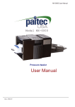
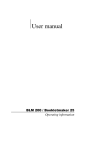
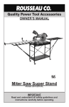
Walker, Michigan, U.S.A. 49534-7564 USER’S OPERATING AND INSTRUCTION MANUAL MODEL 2005 VARIABLE SLICE THICKNESS BREAD SLICER LISTED E65166 2005S20000-CV-1 2005 VARIABLE THICKNESS BREAD SLICER INDEX Section Description Document No. Page No. SAFETY INSTRUCTIONS ------------------------------- 2005S20001 --------------------- 1-1 DESCRIPTION/SPECIFICATIONS -------------------- 2005S20002---------------------- 2-1 Description -------------------------------------------------------------------------------------- 2-1 Physical Specifications----------------------------------------------------------------------- 2-1 OPERATING INSTRUCTIONS ------------------------- 2005S20003 --------------------- 3-1 MAINTENANCE -------------------------------------------- 2005S20004 --------------------Cleaning ----------------------------------------------------------------------------------------Lubrication -------------------------------------------------------------------------------------Changing a Blade ----------------------------------------------------------------------------- 4-1 4-1 4-1 4-1 TROUBLESHOOTING / SET-UP ----------------------2005S20005 --------------------Nothing Happens When the Machine is Turned On ---------------------------------Slice Thicknesses Are Not Equal ---------------------------------------------------------Slices Are Being Pulled Up Or Pushed Down Between the Tables --------------The Blade is Crushing the Bread ---------------------------------------------------------Slicing Starts Before the Bread is Beneath the Blade -------------------------------The Knife Vibrates Excessively -----------------------------------------------------------The Machine Makes a Loud Thumping Sound ----------------------------------------- 5-1 5-1 5-1 5-1 5-2 5-2 5-2 5-2 Manual Diagnostic and Set-Up Mode ------------------------------------------------------5-3 RECOMMENDED SPARE PARTS -------------------- 2005S20006 --------------------- 6-1 REPLACEMENT PARTS SECTION MAIN FRAME ----------------------------------------------- 2005S20007 --------------------- 7-1 Drawing ------------------------------------------------------------------------------------- 7-1 Parts List ----------------------------------------------------------------------------------- 7-2 BLADE & CLUTCH DRIVE ------------------------------ 2005S20008 --------------------- 8-1 Drawing ------------------------------------------------------------------------------------- 8-1 Parts List ----------------------------------------------------------------------------------- 8-2 CUTOFF ARM --------------------------------------------- 2005S20009 --------------------- 9-1 Drawing ------------------------------------------------------------------------------------- 9-1 Parts List ----------------------------------------------------------------------------------- 9-2 Continued 2005S20000 0-1 2005 VARIABLE THICKNESS BREAD SLICER INDEX (Continued) REPLACEMENT PARTS SECTION (Continued) Section Description Document No. Page No. PUSHER WITH STEPPER ----------------------------- 2005S20010 -------------------- 10-1 Drawing ------------------------------------------------------------------------------------ 10-1 Parts List ---------------------------------------------------------------------------------- 10-2 TABLES & COVERS -------------------------------------- 2005S20011 -------------------- 11-1 Drawing ------------------------------------------------------------------------------------ 11-1 Parts List ---------------------------------------------------------------------------------- 11-2 CLUTCH ----------------------------------------------------- 2005S20012 -------------------- 12-1 Drawing ------------------------------------------------------------------------------------ 12-1 Parts List ---------------------------------------------------------------------------------- 12-1 ELECTRICAL SUB-PANEL ----------------------------- 2005S20013 -------------------- 13-1 Drawing ------------------------------------------------------------------------------------ 13-1 Parts List ---------------------------------------------------------------------------------- 13-2 ELECTRICS 1-60-115 VAC ----------------------------- 2005S20014 -------------------- 14-1 Parts List ---------------------------------------------------------------------------------- 14-1 WIRING DIAGRAMS ------------------------------------- 2005S20015 -------------------- 15-1 WARRANTY ------------------------------------------------ GEN 040225 WARRANTY PROCEDURE ---------------------------- GEN 040226 RETURNED PARTS POLICY -------------------------- GEN 040227 REV. 10/16/12 2005S20000 0-2 2005 VARIABLE THICKNESS BREAD SLICER SAFETY INSTRUCTIONS Various safety devices and methods of guarding have been provided on this machine. It is essential; however, that machine operators and maintenance personnel observe the following safety precautions. Improper installation or operation of this equipment may cause injury to personnel or damage to equipment. 1. Read this manual before attempting to set-up and service your machine. Never allow an untrained person to service this machine. 2. Connect the machine to a properly grounded electrical supply that matches the requirements shown on the electrical specification plate and follow specifications of local electrical codes. 3. Disconnect and lock-out the machine from the power supply before cleaning or servicing. 4. Check and secure all guards before starting the machine. 5. Observe all caution and warning labels affixed to the machine. 6. Use only proper replacement parts. 7. Do not wear loose fitting clothing or unrestrained long hair. Shirt tails should be tucked in. 8. Wear proper personal safety equipment. 9. Keep Hands away from the moving parts of this machine while it is in operation. 10. In addition to these general safety instructions, also follow the more specific safety instructions given for the different areas of the machine in the operating instructions. WARNING DO NOT USE FOR OTHER THAN ORIGINALLY INTENDED PURPOSE 2005S20001 1-1 2005 VARIABLE THICKNESS BREAD SLICER DESCRIPTION/SPECIFICATION Description The Oliver Model 2005 is a variable slice thickness bread slicer, which utilizes a new and innovative way to slice bread. The bread is moved past a circular blade, which is mounted to a moving arm, cutting each slice individually to whatever thickness is selected. The slicer is designed for on-demand slicing allowing your customers to choose a slice thickness to satisfy their needs. The 2005 slicer also has a multi-lingual digital display prompting the user with normal operating information. The slicer employs a disc brake on the blade drive motor, which mechanically engages to stop the blade whenever the blade is exposed due to a door being opened, or after the slicing cycle is finished. NOTE THIS MACHINE IS NOT INTENDED TO BE USED TO SLICE WARM, STICKY, NUT AND/OR FRUIT BREADS. Physical Specifications Product Capacities: The slicer will process loaves up to 9 inches by 4-1/4 inches by 15 inches long. Overall Machine size: · Width = 36 inches · Height = 28-1/2 inches, Requiring a minimum of 38” in overhead clearance to open the blade guard. · Depth = 24 inches, 48” inches with Blade Guard all the way open. Net Weight: Approximately 360 pounds. Shipping Weight: Approximately 375 pounds. Slice Thickness: 3/8*, 7/16*, 1/2, 5/8, 3/4, 7/8, 1, and 1-1/2 inches. *These sizes may be omitted by set-up option. Electrics: 3/4 Horse Power, 1 phase, 50/60 hertz, 115 Volts AC, 9 Amps, (20 Amp Dedicated Circuit). Rev 10-12 2005S20002 2-1 2005 VARIABLE THICKNESS BREAD SLICER OVERALL MACHINE DIMENSIONS 2005S20002 2-2 2005 VARIABLE THICKNESS BREAD SLICER OPERATING INSTRUCTIONS Start-up: Close both doors. Turn the machine on. The pusher will move back to home if the machine has been turned off while the pusher is out of the home (farthest left) position. The display will display the Oliver logo and language selections. Standard Operation: · Hold open the left door with left your hand. · Place a loaf of bread on the infeed (left hand) table. · Slide the loaf onto the pins of the pusher so that pins penetrate the loaf, until it is firmly against the front of the pusher block. · Close door(s). NOTE THE MACHINE WILL NOT OPERATE IF EITHER DOOR IS OPEN. · Make a language selection on the touch screen. · Select the appropriate slice thickness setting. · Press the “start” button. · Wait for the bread to be sliced. When the machine stops, the bread will be in the right hand compartment. · Open the right hand door and remove the loaf. · Close the door, allowing the pusher to return to the home position. · Once the pusher has returned and stopped you may repeat the above procedure to slice additional loaves. Stopping: If a slice gets jammed, press STOP, to stop slicing, turn the power off, disconnect and lockout the slicer before trying to clear the machine. CAUTION DO NOT OPEN THE DOORS WHILE THE SLICER IS OPERATING. DOING SO WILL CAUSE SLICING TO STOP. 2005S20003 3-1 2005 VARIABLE THICKNESS BREAD SLICER MAINTENANCE WARNING DISCONNECT AND LOCK OUT THE MACHINE FROM THE POWER SUPPLY BEFORE CLEANING OR SERVICING. REMEMBER TO USE CARE AND WEAR CUT RESISTANT GLOVES WHENEVER YOU ARE WORKING WITH OR NEAR THE BLADE. Cleaning: (daily) Use a mild detergent solution applied with a cloth or spray cleaner on all exterior and interior surfaces as necessary. Use brushes provided with machine to clean openings or recesses in and around in-feed and out-feed tables. Remove and empty contents of the crumb tray daily. Periodically (weekly) remove the blade and clean the blade compartment using the same methods as above. IMPORTANT The blade must be cleaned each day, you Do Not need to remove the blade to clean it. Use a mild detergent solution or spray cleaner. For harder deposits use a non scratch cleaning pad similar to Scotch-brite (tm). Lubrication: All motors and bearings are pre-lubricated and sealed: lubrication in not required. Do Not attempt to oil or grease the motor. Removing the blade: WARNING DISCONNECT AND LOCK OUT THE MACHINE FROM THE POWER SUPPLY BEFORE CLEANING OR SERVICING. REMEMBER TO USE CARE AND WEAR CUT RESISTANT GLOVES WHENEVER YOU ARE WORKING WITH OR NEAR THE BLADE. · Tilt the blade guard forward after removing the knob, (located at the top of the guard), which secures it in place. Gently rest it all the way open. · Remove the blade mounting screw using a 1/2 inch wrench. · Remove the lock-washer, special washer, 2 inch diameter collar, and the circular knife. · The blade can be replaced by reversing the above procedure. · When reinstalling the blade, make sure the beveled side faces the outfeed (FLAT SIDE TOWARD INFEED). Make sure the blade is centered and supported on the arbor. 2005S20004 4-1 2005 VARIABLE THICKNESS BREAD SLICER TROUBLE SHOOTING/ SET-UP GUIDE WARNING DISCONNECT AND LOCK OUT THE MACHINE FROM THE POWER SUPPLY BEFORE CLEANING OR SERVICING. WARNING REMEMBER TO USE CARE AND WEAR CUT RESISTANT GLOVES WHENEVER YOU ARE WORKING WITH OR NEAR THE BLADE. WARNING TROUBLESHOOTING OF ELECTRICAL EQUIPMENT MUST BE PERFORMED BY QUALIFIED PERSONNEL ONLY. Nothing Happens When The Machine Is Turned On. Check to see if the machine is plugged in. Check to see if there is power at the outlet. Check to see if any of the circuit breakers have tripped. They are located near the lower, right hand, rear corner of the machine. Slice Thicknesses Are Not Equal. The bread is not being pressed completely onto the pins of the pusher block, therefore allowing the loaf to shift on the pins between cuts. Bread is getting caught in the gap between the infeed and outfeed tables preventing free movement of the product. Re-adjust the outfeed table for minimum gap, while still allowing free movement of the slicer blade. Do NOT adjust the infeed table. The slicer blade is loose. Check the blade mounting screw and tighten if necessary. Slices Are Being Pulled Up Or Pushed Down Through The Gap Between The Tables. A build-up on the blade from slicing warm bread or sticky fruit breads can cause this type of product damage or malfunction. The gap between the tables is too large. Re-adjust the outfeed table so that the gap between the infeed and outfeed tables is minimized while still allowing a comfortable clearance for the spinning knife. The arms of the hold-down could be bent to far away from the blade so that they cannot maintain control over the slices or crusts and they are pulled between the blade and hold-down. 2005S20005 5-1 2005 VARIABLE THICKNESS BREAD SLICER The Blade Is Crushing The Bread. The bread may be too warm for slicing. A build-up on the blade from slicing warm bread or sticky fruit breads can cause this type of product damage or malfunction. The slicer drive motor may not be running, (the slicer knife will not be rotating). The motor is protected by a circuit breaker, located on the back of the machine, which may need to be reset. The Knife has become extremely dull and needs to be replaced. Slicing Begins Too Soon, The Knife Takes Several Strokes Before The Product Is Beneath The Knife. The reflector inside of the Knife Cover is dirty. The “Product Detect” scanner is dirty or has failed. The Knife Vibrates Excessively. Loose or mis-aligned knife or clutch drive belt’(s). Align or re-tighten as necessary. The Machine Makes A Loud Thumping Sound Before Making The First Slice. Check for a loose blade drive V-belt, or clutch drive belt. 2005S20005 5-2 2005 VARIABLE THICKNESS BREAD SLICER Manual Diagnostic and Set-Up Mode: The machine may be put into Manual Diagnostic Mode to check several functions of the machine. To enter this mode, simply do the following: Wait for the initial screen to come up (pusher must be in the home position, and may take up to a minute) or cycle the power switch to bring up the initial screen. Press on the Varislice logo on the touch screen for about 20 seconds until the screen changes. There are several rectangular buttons on the touch screen display to activate the different actuators and colored (red/green) circle indicators to verify the switch function on the machine as follows: 1. FWD and REV buttons move the pusher back and forth. (The covers must be closed to allow movement). Moving the pusher can verify the smoothness of the pusher travel and can be used to test the switches on each end of the travel by observing the “end switch” indicator (right end) and “home switch” indicator (left end). 2. The BLD button starts the blade rotation. (The covers must be closed to allow movement). 3. The ARM button engages the arm motor and clutch to move the blade arm up and down. (The covers must be closed to allow movement). Moving the arm will activate the switch at the top of the arm travel. The function of this switch can be verified by observing the “ARM SWITCH” indicator as the arm returns upward. 2005S20005 5-3 2005 VARIABLE THICKNESS BREAD SLICER 4. The function of the switches for the doors can be verified as the doors are opened and closed by observing the “R DOOR” and “L DOOR” switches. 5. The function of the bread sensor can be verified by blocking the photo eye on the back wall of the bread platform (near the blade slot) and observing the “BREAD SWITCH” indicator. This sensor can also be activated by moving the pusher to the far right end of its travel to block the photo eye. 6. A continuous operation mode can be activated by pressing the CONT button. This will cause all the functions of the machine to operate in sequence as if it were continuously cutting bread. (The covers must be closed to allow movement). This is used to observe the machine without cutting bread and for repetitively test running. It is best stopped by pressing the STOP/HOME button. 7. Heel Size: This is to program the final slice thickness. The value is in eighths of an inch. For example, Heel Val=8 would be 8/8 inch or 1 inch, or Heel Val=7 would be 7/8 inch. The range of Heel Values is 6 to 12, which equates to ¾” to 1 ½”. The factory recommended setting is “8”. Depress the "3" key to continue to the next test. 8. Loaf counter – The loaf counter can be seen and reset here. This counter is for convenience for tracking machine usage or blade usage for considering blade replacement. 9. Thin Size Lockout: Press the color rectangle to change “Off” and “On” state. “On” eliminates the thinnest two slice size selections (3/8” and 7/16”). Revised 12-12-12 2005S20005 5-4 2005 VARIABLE THICKNESS BREAD SLICER RECOMMENDED SPARE PARTS PART NUMBER PART DESCRIPTION 2005-25018K 2003-0006 2005-0115 5757-7540 5250-0386 5250-0387 5251-3420 5254-3190 5254-3507 5601-1033 5601-3341 5601-3420 5601-3450 5711-9011 5840-1020 5840-1026 5840-1125 5840-1128 6309-6014 5749-8027 5757-4125 5757-4279 5757-4358 4560-2508-1106 Cleaning Kit Plate-Pusher W/Pins Eye-Photo W/Harness Switch-Reed W/ connectors Bearing-Ball 1/2 X 1-1/8 Bearing-Ball 5/8 X 1-3/8 Bearing-Ball 4B Flange Bearing-Bronze Flange Bearing-Thrust Belt-V 3L230 Belt-Timing 300L075 Belt-Timing 510L050 Belt-Timing 165L050 Reflector-3” Round Ring-Retaining N5000-112 Ring-Retaining N5000-137 Ring-Retaining #5100-50 Ring-Retaining #5100-62 Resistor-Control (Plug-In) Relay-Power Breaker-Circuit 2.5A Breaker-Circuit 5.0A Breaker-Circuit 15.0A Knob-Screw NO. REQ’D. 1 1 1 6 1 8 2 1 1 2 1 1 1 1 2 2 1 5 1 1 1 1 1 1 OPTIONAL SPARE PARTS 2001-0019 5746-5672 6309-6000 6300-0017 5604-5257 2005-0118 2005-0119 6301-5611 6310-0008 7107-7056 Shaft-Clutch Drive Power Supply AC/DC Control-DC Drive Motor-Stepping Clutch-CB-5 PLC (pre-programmed) Touch Screen (pre-programmed) Motor-Brake 3/4 HP (115/230 VAC) Gearmotor (1/8 HP 90 VDC) Knife-Scalloped Circular 1 1 1 1 1 1 1 1 1 1 Rev. 10-16-12 2005S20006 6-1 2005 VARIABLE THICKNESS BREAD SLICER MAIN FRAME ASSEMBLY Rev. 10-8-03 2005S20007 7-1 2005 VARIABLE THICKNESS BREAD SLICER MAIN FRAME PARTS LIST ITEM NO. PART DESCRIPTION PART NUMBER 001 Main Frame 2005-0054 002 Cover-Electrical 2003-0021 003 Track-Crumb Tray 2003-0038 004 Bumper-Rubber 5902-0021 005 Plate-Face 2003-0003 006 Tray-Crumb 2003-0037 007 Angle-Table Support 2003-0011-1 008 Spacer-Angle 2003-0034 *009 Stiffener 2003-0054-1 *010 Plate-splice 2005-0058 *Not shown on drawing Rev. 1/25/05 2005S20007 7-2 2005 VARIABLE THICKNESS BREAD SLICER BLADE & CLUTCH DRIVE ASSEMBLY 2005S20008 8-1 2005 VARIABLE THICKNESS BREAD SLICER BLADE & CLUTCH DRIVE PARTS LIST ITEM NO. PART DESCRIPTION PART NUMBER 101 Motor-Brake 3/4 HP 6301-5611 103 Sheave 3L, 2-Grooves 1.5 OD 2003-0070 104 Belt-V 3L230 5601-1033 301 Nutbar 2001-0015 302 Gearmotor 1/8 HP DC (115 VAC) 6310-0008 304 Pulley-Timing Belt 4495-2816-2001 2005S20008 8-2 2005 VARIABLE THICKNESS BREAD SLICER CUTOFF ARM ASSEMBLY 2005S20009 9-1 2005 VARIABLE THICKNESS BREAD SLICER CUTOFF ARM PARTS LIST ITEM NO. PART DESCRIPTION PART NUMBER 201 Block-Pivot Outside 2001-0041 202 Bearing-Ball 5250-0387 203 Ring-Retaining #N5000-137 5840-1026 204 Shaft-Drive 2001-0047-1 205 Pulley-Timing Belt 2003-0044 206 Sheave-3L, 2-Grooves 3.882 OD 2003-0071 207 Ring-Retaining #5100-62 5840-1128 208 Side-RH Arm 2003-0046-1 209 Side-LH Arm 2003-0047 210 Spacer-Aluminum Tube 2003-0050 211 Trunnion 2003-0052 212 Flag 2005-0036 214 Holddown 2003-0064 215 Bearing-Bronze Flange 5254-3190 217 Ring-Retaining #5100-50 5840-1125 218 Spring-Extension 7021-4005 219 Belt-Timing 300L075 5601-3341 220 Spindle-Blade 2001-0072-101 222 Disk/Collar 2001-0073-001 223 Washer-Special 2001-0074 224 Knife-Scalloped 7107-7056 225 Rod-Connecting 2003-0027 226 Screw-Shoulder 1/2 X 1-1/4 5842-8545 227 Cover-Top 2003-0048 228 Cover-Bottom 2003-0049 229 Bearing-Bronze Thrust 5254-3507 230 Bushing-Stop 2003-0065 231 Pin-Coiled 5835-7625 2005S20009 9-2 2005 VARIABLE THICKNESS BREAD SLICER PUSHER WITH STEPPER ASSEMBLY Rev. 10-8-03 2005S20010 10-1 2005 VARIABLE THICKNESS BREAD SLICER PUSHER WITH STEPPER PARTS LIST ITEM NO. PART DESCRIPTION PART NUMBER 401 Bar-Motor 2005-0049 402 Motor-Stepper 6300-0017 404 Pulley-Timing Belt 2005-0039 405 Belt-Timing # 510L050 5601-3420 406 Spindle-Idler 2001-0051 407 Pulley-Idler Timing 2001-0050 408 Bearing-Ball 5250-0386 409 Ring-Retaining # N5000-112 5840-1020 410 Clamp-Belt 2001-0034 411 Hitch-Pusher 2003-0007 412 Block-Center Wear 2001-0046 413 Pad-Bottom Wear 2003-0010 414 Bracket-Magnet 2005-0047-1 415 Block-Pusher 2003-0005 416 Wiper Blade Assembly 2003-0009 417 Bracket-Pusher 2001-0035 418 Nutbar-Pusher 2001-0089 419 Plate-Pusher W/Pins 2003-0006 Rev. 10-8-03 2005S20010 10-2 2005 VARIABLE THICKNESS BREAD SLICER TABLE & COVER ASSEMBLY Rev. 10-8-03 2005S20011 11-1 2005 VARIABLE THICKNESS BREAD SLICER TABLE & COVER PARTS LIST ITEM NO. PART DESCRIPTION PART NUMBER 501 Guard-Blade 2005-0014-001 502 Knob-Screw 4560-2508-1106 503 Panel-Infeed 2005-0043-001 504 Nutbar-Infeed 2001-0102-001 505 Table-Rear Adj. Infeed 2005-0050-1 506 Pin 1/4 Diameter X 3/4 4475-0516-075 507 Nut-Cage 1/4-20 5832-0425 508 Nutbar-Outfeed 2001-0103-001 509 Table-Front Adj. Infeed 2005-0048-1 510 Panel-Outfeed 2005-0044-001 511 Table-Rear Adj. Outfeed 2005-0052 512 Hinge-Type “A” 5908-9845 513 Hinge-Type “B” 5908-9846 514 Cover-Infeed 2005-0041 515 Plate-Hinge Backer 2005-0046 516 Cover-Outfeed 2005-0040 518 Strip-Handle Backer 2000-0087 519 Handle-Pull 5908-5100 520 Chute-Lower Crumb 2003-0030 521 Chute-Upper Crumb 2005-0012 530 Catch-Magnetic W/Strike 5805-2503 531 Table-Bottom Adj. Infeed 2005-0051-2 532 Table-Bottom Adj. Outfeed 2005-0053 533 Spacer-Table 2005-0061 868 Reflector-3” Round 5711-9011 869 Bracket-Reflector 2005-0019 Rev. 10.8-03 2005S20011 11-2 2005 VARIABLE THICKNESS BREAD SLICER CLUTCH ASSEMBLY Rev. 12/13/12 CLUTCH ASSEMBLY PARTS LIST ITEM NO. PART DESCRIPTION PART NUMBER 701 Bracket-Clutch 2005-0124 702 Spacer 2001-0032 703 Bearing-Flange Ball 5251-3420 704 Clutch 5604-5257 705 Cover-Clutch 5604-5518 706 Spacer-Anchor 2001-0017 707 Plate-Anchor 2001-0033 708 Pulley-Timing Belt 2001-0001 709 Belt-Timing # 165L050 5601-3450 2005S20012 12-1 2005 VARIABLE THICKNESS BREAD SLICER 710 Shaft-Drive 2005-0123 711 Crank 2003-0028 712 Key 4384-0404-075 713 Cam, Arm Switch 2005-0120 714 Switch, Roller 5757-8002 715 Block, Limit Switch Spacer 1908-0408 716 Plate, Arm Switch 2005-0121 Rev. 12/13/12 2005S20012 12-2 2005 VARIABLE THICKNESS BREAD SLICER ELECTRICAL SUB-PANEL ASSEMBLY 2005S20013 13-1 2005 VARIABLE THICKNESS BREAD SLICER ELECTRICS 1-60-115 PARTS LIST ITEM NO. PART DESCRIPTION PART NUMBER 820 Switch-Reed 5757-7540 821 Washer 8851-8466 822 Cord-Power 115V 2005-0102 823 Bushing-Strain Relief 5765-1079 824 Harness-Wire (Stepper) 2005-0100 825 Wire-Ground 6” 2005-0037 826 Harness-Wire 18” (Arm Sensor) 2005-0113 827 Harness-Wire (LT Door Switch) 2005-0112 828 Harness-Wire (RT Door Switch) 2005-0111 829 Eye-Photo 2005-0115 830 Harness-Wire (Drive Motor) 2005-0101 831 Harness-Wire (DC Motor) 2005-0029 832 Wire (Clutch) 2005-0107 833 Wire (Clutch) 2005-0108 834 Grommet (1/16” W/Groove) 5767-1208 835 Grommet (1/8” W/Groove) 5767-1206 836 Reflector-3” Round 5711-9011 837 Bracket-Reflector 2005-0019 838 Operator Interface (Programmed) 2005-0119 839 Cable- Operator Interface 5744-1003 840 Switch- Main Power Rocker 5757-3307 841 Duct-Wiring 5766-3301 842 Cover-Wiring Duct 5766-3325 843 Breaker-Circuit 2.5A 5757-4125 844 Breaker-Circuit 5.0A 5757-4279 845 Breaker-Circuit 15.0A 5757-4358 846 Resistor-DC Motor Control 6309-6014 847 Resistor- 2.2K Ohm 5750-2311 Rev. 3/11/13 2005S20014 14-1 2005 VARIABLE THICKNESS BREAD SLICER WIRE DIAGRAM 1-60-115 PAGE 1 OF 3 2005S20015 15-1 2005 VARIABLE THICKNESS BREAD SLICER WIRE DIAGRAM 1-60-115 PAGE 2 OF 3 2005S20015 15-2 2005 VARIABLE THICKNESS BREAD SLICER WIRE DIAGRAM 1-60-115 PAGE 3 OF 3 REV. 12-13-12 2005S20015 15-3 WARRANTY PARTS Oliver Packaging & Equipment Company warrants that if any part of the equipment (other than a part not manufactured by Oliver Packaging & Equipment ) proves to be defective (as defined below) within one year after shipment, and if Buyer returns the defective part to Oliver Packaging & Equipment within one year, Freight Prepaid to Oliver Packaging & Equipment plant in Grand Rapids, MI, then Oliver Packaging & Equipment , shall, at Oliver Packaging & Equipment option, either repair or replace the defective part, at Oliver Packaging & Equipment expense. LABOR Oliver further warrants that equipment properly installed in accordance with our special instructions, which proves to be defective in material or workmanship under normal use within one (1) year from installation or one (1) year and three (3) months from actual shipment date, whichever date comes first, will be repaired by Oliver Packaging & Equipment or an Oliver Packaging & Equipment Authorized Service Dealer, in accordance with Oliver Packaging & Equipment published Service Schedule. For purposes of this warranty, a defective part or defective equipment is a part or equipment which is found by Oliver Packaging & Equipment to have been defective in materials workmanship, if the defect materially impairs the value of the equipment to Buyer. Oliver Packaging & Equipment has no obligation as to parts or components not manufactured by Oliver Packaging & Equipment, but Oliver Packaging & Equipment assigns to Buyer any warranties made to Oliver Packaging & Equipment by the manufacturer thereof. This warranty does not apply to: 1. Damage caused by shipping or accident. 2. Damage resulting from improper installation or alteration. 3. Equipment misused, abused, altered, not maintained on a regular basis, operated carelessly, or used in abnormal conditions. 4. Equipment used in conjunction with products of other manufacturers unless such use is approved by Oliver Packaging & Equipment Company in writing. 5. Periodic maintenance of equipment, including but not limited to lubrication, replacement of wear items, and other adjustments required due to installation, set up, or normal wear. 6. Losses or damage resulting from malfunction. The foregoing warranty is in lieu of all other warranties expressed or implied AND OLIVER PACKAGING & EQUIPMENT COMPANY MAKES NO WARRANTY OF MERCHANTABILITY OR FITNESS FOR PURPOSE REGARDING THE EQUIPMENT COVERED BY THIS WARRANTY. Oliver Packaging & Equipment Company neither assumes nor authorizes any person to assume for it any other obligations or liability in connection with said equipment. OLIVER PACKAGING & EQUIPMENT COMPANY SHALL NOT BE LIABLE FOR LOSS OF TIME, INCONVENIENCE, COMMERCIAL LOSS, INCIDENTAL OR CONSEQUENTIAL DAMAGES. GEN 040225 WARRANTY PROCEDURE 1. If a problem should occur, either the dealer or the end user must contact the Parts and Service Department and explain the problem. 2. The Parts and Service Manager will determine if the warranty will apply to this particular problem. 3. If the Parts and Service Manager approves, a Work Authorization Number will be generated, and the appropriate service agency will perform the service. 4. The service dealer will then complete an invoice and send it to the Parts and Service Department at Oliver Packaging & Equipment Company. 5. The Parts and Service Manager of Oliver Packaging and Equipment Company will review the invoice and returned parts, if applicable, and approve for payment. GEN 040226 RETURNED PARTS POLICY This policy applies to all parts returned to the factory whether for warranted credit, replacement, repair or re-stocking. Oliver Packaging and Equipment Company requires that the customer obtain a Return Material Authorization (RMA) number before returning any part. This number should appear on the shipping label and inside the shipping carton as well. All parts are to be returned prepaid. Following this procedure will insure prompt handling of all returned parts. To obtain an RMA number contact the Repair Parts Deptartment toll free at (800) 253-3893. Parts returned for re-stocking are subject to a RE-STOCKING CHARGE. Thank you for your cooperation, Repair Parts Manager Oliver Packaging and Equipment Company GEN 040227