1
pickering
USER MANUAL
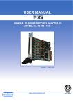
PXI SHIELDED REED RELAY MODULES
(MODEL No. 40-120 / 125)
Issue 3, Apr 2007
pickering
www.pickeringtest.com
SHIELDED REED RELAY MODULES 40-120/125
ISO 9002
Reg No. FM38792
Page pickering
© Copyright (2007) Pickering Interfaces. All Rights Reserved.
No part of this publication may be reproduced, transmitted, transcribed, translated or stored in any form, or
by any means without the written permission of Pickering Interfaces.
Technical details contained within this publication are subject to change without notice.
Page ii
SHIELDED REED RELAY MODULES 40-120/125
pickering
TECHNICAL SUPPORT
For Technical Support please contact Pickering Interfaces either by phone, fax, the website or via e-mail.
WARRANTY
All products manufactured by Pickering Interfaces are warranted against defective materials and workmanship for a
period of two years, excluding PXI chassis, from the date of delivery to the original purchaser. Any product found to be
defective within this period will, at the discretion of Pickering Interfaces be repaired or replaced.
Products serviced and repaired outside of the warranty period are warranted for ninety days.
Extended warranty and service are available. Please contact Pickering Interfaces by phone, fax, the website or via
e-mail.
ENVIRONMENTAL POLICY
Pickering Interfaces operates under an environmental management system similar to ISO 14001.
Pickering Interfaces strives to fulfil all relevant environmental laws and regulations and reduce wastes and releases
to the environment. Pickering Interfaces aims to design and operate products in a way that protects the environment
and the health and safety of its employees, customers and the public. Pickering Interfaces endeavours to develop
and manufacture products that can be produced, distributed, used and recycled, or disposed of, in a safe and
environmentally friendly manner.
Observe the Electrical Hazard Warning detailed in Section 9.
Observe the Electrostatic Sensitive Device Caution detailed in Section 9.
Worldwide Technical Support and Product Information
http://www.pickeringtest.com
Pickering Interfaces Headquarters
Stephenson Road Clacton-on-Sea CO15 4NL United Kingdom
Tel:
+44 (0)1255-687900
Fax:
+44 (0)1255-475058
E-Mail:
[email protected]
Pickering Interfaces SARL
6 Rue De La Mare Blanche
77186 Noisiel
Marne Le Vallee
France
Tel +33 1 60 53 55 50
Fax +33 1 60 53 55 99
email [email protected]
Pickering Interfaces Inc.
2900 Northwest Vine Street
Grants Pass
Oregon 97526
USA
Pickering Interfaces GmbH
Buchenstrasse 15
D-77880
Sasbach
Germany
Pickering Interfaces AB
Karl Nordströmsväg 31
432 53
Varberg
Sweden
Tel: +1 541 471 0700
Fax: +1 541 471 8828
E-Mail: [email protected]
Tel: +49 7841 66 49 10
Fax: +49 7841 66 49 12
E-Mail: [email protected]
Tel: +46 340-69 06 69
Fax: +46 340-69 06 68
E-Mail: [email protected]
Pickering Interfaces Inc.
(East Coast Regional Office)
12 Alfred Street Suite 300-3
Woburn Massachusetts 01801
USA
Pickering Interfaces GmbH
(Office Munich)
Feringastrasse 6
D-85774 München
Germany
Pickering Interfaces s.r.o.
Smetanova 525
ˇ
Trinec
739 61
Czech Republic
Tel: +1 781 897 1710
Fax: +1 781 897 1701
E-mail: [email protected]
Tel: +49 8999 216 160
Fax: +49 8999 216 200
E-mail: [email protected]
Tel: +42 0558 339 168
Fax: +42 0558 339 168
E-mail: [email protected]
SHIELDED REED RELAY MODULES 40-120/125
Page iii
pickering
THIS PAGE INTENTIONALLY BLANK
Page iv
SHIELDED REED RELAY MODULES 40-120/125
pickering
CONTENTS
Copyright Statement........................................................... ii
Technical Support and Warranty........................................ iii
Contents (this page)............................................................ v
Section 1
Introduction.......................................................................... 1.1
Section 2
Technical Specification....................................................... 2.1
Section 3
Installation............................................................................ 3.1
Section 4
Programming....................................................................... 4.1
Section 5
Connector Pin Outs............................................................. 5.1
Section 6
Troubleshooting.................................................................. 6.1
Section 7
Functional Description........................................................ 7.1
Section 8
Parts List.............................................................................. 8.1
Section 9
Warnings and Cautions..................................................... 9.1
SHIELDED REED RELAY MODULES 40-120/125
Page pickering
THIS PAGE INTENTIONALLY BLANK
Page vi
SHIELDED REED RELAY MODULES 40-120/125
Section 1 - introduction
pickering
SECTION 1 - INTRODUCTION
GENERAL
The 40-12* range of Reed Relay Modules form part of the System 40 PXI Programmable Switching system. The
functionality of each module in the range is the same, the part number being derived from the number, and type of
relays (e.g. single or two pole, etc). This module is used for construction of small switching networks, for slaving up
to larger switches, or for operating external devices.
The Relay Module is provided in the following configurations:
•
•
•
16 x SPDT Shielded Reed Relay (Part Number 40-120-021)
16 x SPDT Shielded Reed Relay (Part Number 40-125-021)
24 x SPST Shielded Reed Relay (Part Number 40-125-121)
SHIELDED REED RELAY MODULES 40-120/125
Page 1.
Section 1 - introduction
pickering
THIS PAGE INTENTIONALLY BLANK
Page 1.
SHIELDED REED RELAY MODULES 40-120/125
Section 2 - SPECIFICATION
pickering
SECTION 2 - SPECIFICATION
B1
A1
C1
A1
C1
A2
C2
A3
C3
B2
A2
C2
B 32
A 32
C 32
A 32
C 32
40-110-121
S B1
B1
A1
S A1
A 1.1
C 1.1
A 1.2
C 1.2
A 2.1
C 2.1
A 2.2
C 2.2
A 24.1
C 24.1
A 24.2
C 24.2
40-115-122
40-115-121
C1
S C1
S B2
B2
A2
S A2
C2
S C2
S B16
B 16
A 16
S A16
C 16
S C16
A1
S A1
C1
S C1
A2
S A2
C2
S C2
A2
S A2
C2
S C2
A 24
S A24
C 24
S C24
40-120-021
40-125-121
Switching Diagrams for the 40-110/115/120/125 Reed Relay Module
Safety & CE Compliance
All modules are fully CE compliant and meet applicable EU
directives: Low-voltage safety EN61010-1:2001,
EMC Immunity EN61000-6-1:2001, Emissions EN55011:1998.
Switching Specification
Switch Type:
Ruthenium Reed
Max Switch Voltage:
150V DC/100V AC
Max Power:
Max Switch Current:
Max Carry Current:
20W (3W for SPDT)
1A (0.25A for SPDT)
1.2A (1A for SPDT)
On Path Resistance
Off Path Resistance
Differential Thermal Offset:
<250mΩ
>109Ω
<10µV
Crosstalk (100Ω balanced):
80dB (1MHz), 72dB (10MHz)
62dB (25MHz)
75dB (1MHz), 60dB (10MHz)
55dB (25MHz)
Bandwidth (-3dB):
(measured on 40-120)
70MHz (typical)
Operate Time:
Release Time:
<0.5ms, 0.25ms typ.
<0.5ms, 0.25ms typ.
Expected Life, low power:
Expected Life, high power:
1x10⁹ operations
>1x10⁶ operations
PXI bus via 32-bit P1/J1 backplane connector.
Signals via front panel 96 Way male SCSI connector, for pin outs
please refer to the operating manual.
Product Order Codes
16 x SPDT, Ruthenium Reed Relays
32 x SPDT, Ruthenium Reed Relays
16 x SPST, Ruthenium Reed Relays
32 x SPST, Ruthenium Reed Relays
16 x DPST, Ruthenium Reed Relays
24 x DPST, Ruthenium Reed Relays
16 x Shielded SPDT Reed Relays
16 x Shielded SPST Reed Relays
24 x Shielded SPST Reed Relays
40-110-021
40-110-121
40-115-021
40-115-121
40-115-022
40-115-122
40-120-021
40-125-021
40-125-121
Mating Connectors & Cabling
Examples of connectors and cabling for the 40-110 series are:
Programming
Pickering provide kernel, VISA and IVI drivers which are
compatible with Windows 2000/NT/XP operating systems,
the VISA driver is also compatible with the LabVIEW RT
operating system.
These drivers may be used with a variety of programming
environments and applications including :National Instruments products (LabVIEW/LabWindows/CVI/
Switch Executive/MAX/TestStand etc.)
Microsoft Visual Studio products (Visual Basic/Visual C+)
Agilent VEE
Mathworks Matlab
Other environments are also supported, please contact
Pickering with specific enquiries.
Power Requirements
+3.3V
+5V
+12V
-12V
0
360mA (typ 280mA)
0
0
40-961-096
96 way SCSI style ribbon cable connector
40-970-096-1M Cableform, 96 way SCSI Style, Female to
Female, 1A, 1m Length
40-965-096
Connector Block, Shielded, 96 way SCSI
Style, Module Mounted
Please refer to the Pickering Interfaces “Interconnection
Solutions” catalog for the full list of connector/cabling
options, including drawings, photos and specifications.
This is available in either print or as a download.
Alternatively our web site has dynamically linked connector/
cabling options, including pricing, for all Pickering PXI modules.
Latest Details
Please refer to our Web Site for Latest Product Details.
www.pickeringtest.com
Operating/Storage Conditions
Operating Conditions
Operating Temperature:
Humidity:
Altitude:
Width and Dimensions
Single slot 3U PXI (CompactPCI card).
0°C to 55°C
Up to 95% non-condensing
5000m
Storage and Transport Conditions
PXI & CompactPCI Compliance
All Pickering Interfaces PXI modules comply with the PXI
Specification. Local Bus, Interrupts, Trigger Bus and Star Trigger
are not implemented.
Storage Temperature:
Humidity:
Altitude:
-20°C to +75°C
Up to 95% non-condensing
15000m
SHIELDED REED RELAY MODULES 40-120/125
Page 2.
Pickering Interfaces are sponsor members of the PXI Systems Alliance www.pxisa.org
© Copyright (2006) Pickering Interfaces. All Rights Reserved
Pickering Interfaces maintains a commitment to continuous product development, consequently we reserve the right to vary from the description given in this data sheet.
Isolation (100Ω balanced):
Connectors
Section 2 - SPECIFICATION
pickering
THIS PAGE INTENTIONALLY BLANK
Page 2.
SHIELDED REED RELAY MODULES 40-120/125
Section 3 - inSTALLATION
pickering
SECTION 3 - INSTALLATION
Software Installation
First install the appropriate Pickering PXI switch card drivers by running the installer program Setup.exe, either
from the CD-ROM supplied, or by downloading the latest version from our website http://www.pickeringtest.com
- the recommended method. There are different versions of the Setup program to suit different Windows versions
and software environments. Setup is accompanied by a ReadMe file containing additional installation information.
A single installation covers all cards in the System 40, System 45 and System 50 ranges.
When installation completes, the installed drivers’ ReadMe file is offered for display. It can also be displayed later
using a shortcut on the Programs>>Pickering menu.
If you are not a LabVIEW user you should choose the “full” version, and once that has been installed run the
LabVIEW Runtime Engine installer via the shortcut on the Programs>>Pickering menu. In the absence of LabVIEW
the Runtime Engine is required to support the Pickering Test Panels application.
Hardware Installation
CAUTION
Electrostatic discharge can damage the components on the module. To avoid such damage in handling the board,
touch the anti-static bag to a metal part of the chassis before removing the board from the bag.
Ensure that there is adequate ventilation in accordance with the PXI Specification
The module should be installed in accordance with the following procedure:
1. Ensure that the system is turned OFF but still connected to mains so that it remains grounded.
2. Choose an appropriate slot in the rack.
3. Remove the blanking plate for the chosen slot.
4. Ensure that the injector/ejector handle is in its downward position. Align the module with the card guides on the
top and bottom of the slot.
CAUTION
Do not raise the injector/ejector handle whilst inserting the module. The module will not insert properly unless the
handle is in its downward position.
5. Hold the handle whilst slowly sliding the module into the card guides until the handle catches on the injector/
ejector rail (refer to Figure 3.1).
6. Raise the injector/ejector handle until the module firmly seats into the backplane. The front panel of the module
should be flush with the front panel of the chassis.
7. Screw the front panel of the module to the front panel mounting rail.
8. In a system employing MXI-3 to connect a desktop PC to a PXI chassis or to link multiple chassis, power-up the
system as follows:
a. For a system comprising a PC and one chassis, power up the chassis before powering up the PC.
b. For a system comprising more than one chassis, turn ON the last chassis in the system followed by the
penultimate, etc, and finally turn ON the PC or chassis containing the system controller.
SHIELDED REED RELAY MODULES 40-120/125
Page 3.
Section 3 - inSTALLATION
pickering
Figure 3.1 - Installing the module into a PXI/Compact PCI Chassis
Testing Operation
Start the Test Panels application from the Programs>>Pickering>>PXI Utilities menu. If you are a LabVIEW user, run
“Test Panels (LabVIEW VI)”; if not, run “Test Panels (EXE)”. A selector panel will appear, listing all installed Pickering
PXI switch cards. Click on the card you wish to control, and a graphical control panel is presented allowing operation of
the card. Panels can be opened simultaneously for all the installed cards.
Figure 3.2 - Typical Test Panel Display
Page 3.
SHIELDED REED RELAY MODULES 40-120/125
pickering
Section 3 - inSTALLATION
As an alternative to the Test Panels, the simple Terminal Monitor program PILMon (again on the
Programs>>Pickering>>PXI Utilities menu) allows access to all functions of Pickering switch cards through a
command-line interface. In PILMon, enter “HE” for help on it’s commands.
Please note that both the Test Panels and Terminal Monitor gain exclusive access to the cards, and so only one of
them can be operational at any time.
SHIELDED REED RELAY MODULES 40-120/125
Page 3.
Section 3 - inSTALLATION
pickering
THIS PAGE INTENTIONALLY BLANK
Page 3.
SHIELDED REED RELAY MODULES 40-120/125
Section 4 - PROGRAMMING
pickering
SECTION 4 - PROGRAMMING
System 40, System 45 and System 50 cards are supported by comprehensive Windows software drivers and can
also be programmed at register-level.
There are two separate Windows drivers, one accessing cards by Direct I/O and the other through VISA (Virtual
Instrument Software Architecture). Both are fully documented by ReadMe and HTML help files, accessible through
shortcuts on the Programs>>Pickering menu.
The following programming environments are supported for both drivers:
•
•
•
•
•
Microsoft Visual Basic
Microsoft Visual C++
Borland C++
National Instruments LabWindows/CVI
National Instruments LabVIEW
Support for all these environments is included in the standard installation.
Please refer to the PXI Switching Programming Manual for complete programming information. This manual is
available on the Pickering Interfaces website at http://www.pickeringtest.com.
SHIELDED REED RELAY MODULES 40-120/125
Page 4.
Section 4 - PROGRAMMING
pickering
THIS PAGE INTENTIONALLY BLANK
Page 4.
SHIELDED REED RELAY MODULES 40-120/125
Section 5 - PIN OUTS
pickering
SECTION 5 - CONNECTOR PIN OUTS
Figures 5.1 and 5.2 provide pin outs for the Matrix Modules in the 40-120/125 model range.
A1
B1
A2
B2
A3
B3
A4
B4
A5
B5
A6
B6
A7
B7
A8
B8
A9
B9
A10
B10
A11
B11
A12
B12
A13
B13
A14
B14
A15
B15
A16
B16
-
49 1
50 2
51 3
52 4
53 5
54 6
55 7
56 8
57 9
58 10
59 11
60 12
61 13
62 14
63 15
64 16
65 17
66 18
67 19
68 20
69 21
70 22
71 23
72 24
73 25
74 26
75 27
76 28
77 29
78 30
79 31
80 32
81 33
82 34
83 35
84 36
85 37
86 38
87 39
88 40
89 41
90 42
91 43
92 44
93 45
94 46
95 47
96 48
C1
S1
C2
S2
C3
S3
C4
S4
C5
S5
C6
S6
C7
S7
C8
S8
C9
S9
C10
S10
C11
S11
C12
S12
C13
S13
C14
S14
C15
S15
C16
S16
-
40-120-021
Figure 5.1 - Reed Relay Module 40-120: Pin Outs
SHIELDED REED RELAY MODULES 40-120/125
Page 5.
Section 5 - PIN OUTS
pickering
A1
S1
A2
S2
A3
S3
A4
S4
A5
S5
A6
S6
A7
S7
A8
S8
A9
S9
A10
S10
A11
S11
A12
S12
A13
S13
A14
S14
A15
S15
A16
S16
-
49 1
50 2
51 3
52 4
53 5
54 6
55 7
56 8
57 9
58 10
59 11
60 12
61 13
62 14
63 15
64 16
65 17
66 18
67 19
68 20
69 21
70 22
71 23
72 24
73 25
74 26
75 27
76 28
77 29
78 30
79 31
80 32
81 33
82 34
83 35
84 36
85 37
86 38
87 39
88 40
89 41
90 42
91 43
92 44
93 45
94 46
95 47
96 48
40-125-021
C1
S1
A1.1
S1
C2
S2
C3
S3
A2.1
S2
A3.1
C4
S4
C5
S5
C6
S3
A4.1
A6.1
S6
A7.1
S7
C8
S8
C9
S9
A8.1
S8
C11
S11
C12
S12
C13
S13
C14
S14
C15
S15
C16
S16
-
1
2
3
4
5
6
55 7
56 8
57 9
58 10
S4
A5.1
S5
S6
C7
S7
C10
S10
49
50
51
52
53
54
59 11
60 12
61 13
62 14
63 15
A9.1
S9
A10.1
S10
A11.1
S11
A12.1
S12
A13.1
S13
A14.1
S14
A15.1
S15
A16.1
S16
A17.1
S17
A18.1
S18
A19.1
S19
A20.1
S20
A21.1
S21
A22.1
S22
A23.1
S23
A24.1
S24
64 16
65 17
66 18
67 19
68 20
69 21
70 22
71 23
72 24
73 25
74 26
75 27
76 28
77 29
78 30
79 31
80 32
81 33
82 34
83 35
84 36
85 37
86 38
87 39
88 40
89 41
90 42
91 43
92 44
93 45
94 46
95 47
96 48
C1.1
S1
C2.1
S2
C3.1
S3
C4.1
S4
C5.1
S5
C6.1
S6
C7.1
S7
C8.1
S8
C9.1
S9
C10.1
S10
C11.1
S11
C12.1
S12
C13.1
S13
C14.1
S14
C15.1
S15
C16.1
S16
C17.1
S17
C18.1
S18
C19.1
S19
C20.1
S20
C21.1
S21
C22.1
S22
C23.1
S23
C24.1
S24
40-125-121
Figure 5.2 - Reed Relay Module 40-125-021/121: Pin Outs
Page 5.
SHIELDED REED RELAY MODULES 40-120/125
Section 6 - TROUBLESHOOTING
pickering
SECTION 6 - TROUBLESHOOTING
Installation Problems
The Plug & Play functionality of Pickering switch cards generally ensures trouble-free installation.
If you do experience any installation problems you should first ensure that all cards are properly seated in their slots.
Improperly mated cards may go undetected by the operating system, or may be detected as a card of an unknown
type. They can also cause the computer to freeze at various stages in the boot sequence.
If your system employs MXI-3 you should check the integrity of all MXI-3 links. When the system is powered up, and
during Windows start-up, you should expect to see periodic activity on the MXI-3 RX/TX (yellow) indicators, clearing
to leave only the PWR/LNK (green) LEDs illuminated. The RX/TX indicators should show activity when you attempt
to access a card.
Diagnostic Utility
The Pickering Diagnostic Utility (accessible through the Programs>>Pickering>>PXI Utilities menu) generates a
diagnostic report of the system’s PCI configuration, highlighting any potential configuration problems. Specific details
of all installed Pickering switch cards are included. All the installed Pickering switch cards should be listed in the
“Pilpxi information” section - if one or more cards is missing it may be possible to determine the reason by referring to
the PCI configuration dump contained in the report, but interpretation of this information is far from straightforward,
and the best course is to contact Pickering support: [email protected], if possible including a copy of the
diagnostic report.
In the “VISA information” section, if VISA is not installed it’s absence will be reported. This does not affect operation
using the Direct I/O driver, and is not a problem unless you wish to use VISA. VISA is a component of National
Instruments LabWindows/CVI and LabVIEW, or is available as a standalone environment.
If VISA is present and is of a sufficiently recent version, the section “Pipx40 information” should present a listing
similar to “Pilpxi information”.
Please note that the Diagnostic Utility cannot access cards if they are currently opened by some other application,
such as the Test Panels or Terminal Monitor.
SHIELDED REED RELAY MODULES 40-120/125
Page 6.
Section 6 - TROUBLESHOOTING
THIS PAGE INTENTIONALLY BLANK
Page 6.
SHIELDED REED RELAY MODULES 40-120/125
pickering
Section 7 - FUNCTIONAL DESCRIPTION
pickering
SECTION 7 - FUNCTIONAL DESCRIPTION
Mechanical Description
The 40-12* range of Matrix Modules conform to the 3U height (128mm) Eurocard standard. Each module comprises
the following:
•
•
•
•
•
•
•
CPCI Ejector Handle
Front Panel mounted 96-way SCSI 2 Type connector
16 or 24 ShieldedRuthenium Reed Switches
Two spare Shielded Reed Switches
Compact PCI backplane connector
PCI Bridge (U1)
Control Logic
The front panel is secured to the PCB by two M2.5 x 6mm pan-head posi-drive screws.
SHIELDED REED RELAY MODULES 40-120/125
Page 7.
Section 7 - FUNCTIONAL DESCRIPTION
pickering
Functional Description
A functional block diagram is provided in Figure 7.1. The Reed Relay Module is powered by a +5V input via Compact
PCI connector J1. The interface to the user test equipment is via the front panel mounted 96-way SCSI type connector,
J2. The module comprises a PCB populated with shielded single pole, or two pole relays, depending on the module
type. The relays are energised via control signals from relay driver U8. The relay driver is addressed by PCI bridge
U1 to output the required signal. Module configuration is determined by hardwired links and data stored in EEPROM
U7. PCI Bridge U1 is configured by EEPROM U2.
96-WAY SCSI TYPE
CONNECTOR
J1
RELAY CONTACTS
RELAY COILS
COMPACT PCI
BUS
CONNECTOR
J2
RELAY
DRIVER
U8
CONTROL
LOGIC
U3, U4,
U5, U6
PCI
BRIDGE
U1
TERMINATING
RESISTORS
R4 TO R15
+12V
MODULE
CONFIGURATION
U7
+5V
0V
PCI BRIDGE
CONFIGURATION
U2
-12V
Figure 7.1 - Reed Relay Module (40-120/125): Functional Block Diagram
Page 7.
SHIELDED REED RELAY MODULES 40-120/125
Section 8 - PARTS LIST
pickering
SECTION 8 - PARTS LIST
The following pages provide a parts list and component layout diagram for Shielded Reed Relay Modules 40120/125.
SHIELDED REED RELAY MODULES 40-120/125
Page 8.
Section 8 - PARTS LIST
pickering
Table 8.1 provides a parts list and Figure 8.1 a component layout diagram for the 40-120/125 Shielded Reed Relay
Module.
TABLE 8.1 - Shielded Reed Relay Module 40-120/125 Parts List
PCB Location
Pickering Interfaces
Part Number
Part Description
Quantity
R 1, R 2
C/RS/079
RESISTOR N/W 4 x 10k 1206
2
R3
C/RS/085
RESISTOR 10k 0805
1
R 4 t o R 15
C/RS/102
RESISTOR N/W 4 x 10R 1206
12
(40-120-021)
R L1 t o 16, S pare
C/RL/089
107-1-C-12/SHIELDED
16
(40-125-021)
R L1 t o 16, S pare
C/RL/015
102M-1-A-12/SHIELDED
16
(40-125-121)
R L1 t o 24, S pare
C/RL/077
102M-1-A-12/SHIELDED
24
C3 to C21, C23
C/CP/034
CAPACITOR 100nF 0603
18
C1, C2, C22, C24
C/CP/024
CAPACITOR 10uF TANT SMD
4
J1
C/CN/355
cPCI CONNECTOR
1
C/MS/071
FEMALE CODING KEY,
BRILLIANT BLUE, V
1
J2
C/CP/379
SCSI3 68 PIN
1
U1
C/IC/098
PCI9050 PQFP
1
U2
C/IC/099
93CS46 DIP
1
C/IC/035
8 PIN DIP SKT
1
U3
C/IC/056
7705 S O P
1
U4
C/IC/087
74HCT32 SOP
1
U5
C/IC/100
74HCT273 SOP
1
U6
C/IC/101
74HCT244 SOP
1
U7
C/IC/090
93C 56 S O P
1
U8
C/IC/081
UCN5832EP
1
Page 8.
SHIELDED REED RELAY MODULES 40-120/125
Section 8 - PARTS LIST
pickering
RL1
RL2
RL3
RL4
C19
C24
+
C18
U8
C23
RL7
RL8
C13
RL14
RL15
RL16
RL17
RL18
RL19
RL20
U5
RL13
R3
C8
C9
C4
+
U4
C10
R2
R4
R5
R6
C7
ABCABCABCABCABCABC
RL34
C17
R1
C11
C20 C12
R7
RL21
RL22
RL23
RL24
RL26
RL27
R9
C6
ABCABCABCABCABCABC
RL25
R8
J1
R10
U1
R11
RL28
R12
C5
ABCABCABCABCABCABC
R13
R14
RL30
RL31
RL32
R15
C4
C21
ABCABCABCABCABCABC
pickering
C22
C3
+
RL29
+
J2
U3
RL12
U7
RL11
U6
C16
RL10
C14
RL9
RL33
spare
relays
U2
RL6
C15
RL5
C1
Figure 8.1 - Reed Relay Module 40-120/125: Component Layout
SHIELDED REED RELAY MODULES 40-120/125
Page 8.
Section 8 - PARTS LIST
pickering
THIS PAGE INTENTIONALLY BLANK
Page 8.
SHIELDED REED RELAY MODULES 40-120/125
pickering
SECTION 9 - WARNINGS AND CAUTIONS
WARNING - DANGER OF ELECTRIC SHOCK
THIS MODULE MAY CONTAIN HAZARDOUS VOLTAGES. BEFORE REMOVING
THE MODULE FROM THE RACK REMOVE ALL SUPPLIES.
CAUTION
Handling of Electrostatic-Sensitive Semiconductor Devices
Certain semiconductor devices used in the equipment are liable to damage due to static
voltage. Observe the following precautions when handling these devices in their
unterminated state, or sub-units containing these devices:
(1) Persons removing sub-units from an equipment using these devices must
be earthed by a wrist strap and a resistor at the point provided on the equipment.
(2) Soldering irons used during the repair operations must be low voltage types
with earthed tips and isolated from the mains voltage by a double insulated
transformer.
(3)
Outer clothing worn must be unable to generate static charges.
(4) Printed Circuit Boards (PCBs) fitted with these devices must be stored and
transported in anti-static bags.
SHIELDED REED RELAY MODULES 40-120/125
Page 9.
pickering
THIS PAGE INTENTIONALLY BLANK
Page 9.
SHIELDED REED RELAY MODULES 40-120/125