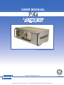
1
Looking for more information?
Visit us on the web at http://www.artisan-scientific.com for more information:
• Price Quotations • Drivers· Technical Specifications. Manuals and Documentation
Artisan Scientific is You~ Source for: Quality New and Certified-Used/Pre:-awned ECJuiflment
• Fast Shipping and DelIve1y
• Tens of Thousands of In-Stock Items
• Equipment Demos
• Hundreds of Manufacturers Supported
• Leasing / Monthly Rentals
Service Center Repairs
Experienced Engineers and Technicians on staff in our
State-of-the-art Full-Service In-House Service Center Facility
• Consignment
InstraView Remote Inspection
Remotely inspect equipment before purchasing with our
Innovative InstraView-website at http://www.instraview.com
We bUy used equipment! We also offer credit for Buy-Backs and Trade-Ins
Sell your excess. underutilized. and idle used equipment. Contact one of our Customer Service Representatives todayl
Talk to a live person: 88EM38-S0URCE fB88-887-68721 I Contact us by email: [email protected] I Visit our website: http://www.artisan-scientific.com
pickering
USER MANUAL
8 - SLOT PXI CHASSIS
(MODEL No. 40-908)
Issue 4.6 September 2010
pickering
www.pickeringtest.com
8 - SLOT PXI CHASSIS 40-908
Artisan Scientific - Quality Instrumentation ... Guaranteed | (888) 88-SOURCE | www.artisan-scientific.com
ISO 9002
Reg No. FM38792
Page 1
pickering
© COPYRIGHT (2010) PICKERING INTERFACES. ALL RIGHTS RESERVED.
No part of this publication may be reproduced, transmitted, transcribed, translated or stored in any form, or by
any means without the written permission of Pickering Interfaces.
Technical details contained within this publication are subject to change without notice.
Page ii
8 - SLOT PXI CHASSIS 40-908
Artisan Scientific - Quality Instrumentation ... Guaranteed | (888) 88-SOURCE | www.artisan-scientific.com
pickering
TECHNICAL SUPPORT
For Technical Support please contact Pickering Interfaces either by phone, fax, the website or via e-mail.
WARRANTY
This product is warranted against defective materials and workmanship for a period of one year from the date of
delivery to the original purchaser. Any product found to be defective within this period will, at the discretion of Pickering
Interfaces be repaired or replaced.
Products serviced and repaired outside of the warranty period are warranted for ninety days.
Extended warranty and service are available. Please contact Pickering Interfaces by phone, fax, the website or via
e-mail.
ENVIRONMENTAL POLICY
Pickering Interfaces operates under an environmental management system similar to ISO 14001.
Pickering Interfaces strives to fulfil all relevant environmental laws and regulations and reduce wastes and releases
to the environment. Pickering Interfaces aims to design and operate products in a way that protects the environment
and the health and safety of its employees, customers and the public. Pickering Interfaces endeavours to develop
and manufacture products that can be produced, distributed, used and recycled, or disposed of, in a safe and
environmentally friendly manner.
Observe the Electrical Hazard Warning detailed in Section 5.
Observe the Electrostatic Sensitive Device Caution detailed in Section 5.
Worldwide Technical Support and Product Information
http://www.pickeringtest.com
Pickering Interfaces Headquarters
Stephenson Road Clacton-on-Sea CO15 4NL United Kingdom
Tel:
+44 (0)1255-687900
Fax:
+44 (0)1255-475058
E-Mail:
[email protected]
Pickering Interfaces Inc.
2900 Northwest Vine Street
Grants Pass
Oregon 97526
USA
Pickering Interfaces GmbH
Johann-Karg-Straße 30
D-85540
Haar-Salmdorf
Germany
Pickering Interfaces AB
Karl Nordströmsväg 31
432 53
Varberg
Sweden
Tel: +1 541 471 0700
Fax: +1 541 471 8828
E-Mail: [email protected]
Tel: +49 89 125 953 160
Fax: +49 89 125 953 189
E-Mail: [email protected]
Tel: +46 340-69 06 69
Fax: +46 340-69 06 68
E-Mail: [email protected]
Pickering Interfaces Inc.
(East Coast Regional Office)
12 Alfred Street Suite 300-3
Woburn Massachusetts 01801
USA
Pickering Interfaces s.r.o.
Smetanova 525
ˇ
Trinec
739 61
Czech Republic
Pickering Interfaces SARL
6 Rue De La Mare Blanche
77186 Noisiel
Marne Le Vallee
France
Tel: +1 781 897 1710
Fax: +1 781 897 1701
E-mail: [email protected]
Tel: +42 0558 339 168
Fax: +42 0558 340 888
E-mail: [email protected]
Tel +33 1 60 53 55 50
Fax +33 1 60 53 55 99
email [email protected]
8 - SLOT PXI CHASSIS 40-908
Artisan Scientific - Quality Instrumentation ... Guaranteed | (888) 88-SOURCE | www.artisan-scientific.com
Page iii
pickering
THIS PAGE INTENTIONALLY BLANK
Page iv
8 - SLOT PXI CHASSIS 40-908
Artisan Scientific - Quality Instrumentation ... Guaranteed | (888) 88-SOURCE | www.artisan-scientific.com
pickering
CONTENTS
Technical Support and Warranty........................................... ii
Copyright Statement.............................................................. iii
Contents (this page).............................................................. v
Section 1 - Introduction
Getting Started...................................................................... 1.1
Unpacking............................................................................. 1.1
Environment.......................................................................... 1.1
Mechanical............................................................................ 1.3
Safety Notice......................................................................... 1.4
Optional Accessories............................................................. 1.5
Section 2 - Technical Specifications
Specifications........................................................................ 2.1
Section 3 - Installation and Configuration
Site Considerations............................................................... 3.1
Cooling Considerations......................................................... 3.1
Fan Speed Setting (40-908-101)........................................... 3.2
Connecting Safety Ground.................................................... 3.3
Install PXI Modules................................................................ 3.3
Backplane.............................................................................. 3.4
Interoperability with cPCI....................................................... 3.4
System ControllerSlot............................................................ 3.4
Local Bus............................................................................... 3.4
Trigger Bus............................................................................ 3.5
Power Supply........................................................................ 3.5
Key Features......................................................................... 3.5
Power Status Indication......................................................... 3.5
Section 4 - Maintenance
Recommended Cleaning Intervals........................................ 4.1
Preparation............................................................................ 4.1
Cleaning................................................................................ 4.1
Section 5 - Warnings and Cautions
Electric Shock and ESD cautions.......................................... 5.1
8 - SLOT PXI CHASSIS 40-908
Artisan Scientific - Quality Instrumentation ... Guaranteed | (888) 88-SOURCE | www.artisan-scientific.com
Page v
pickering
THIS PAGE INTENTIONALLY BLANK
Page vi
8 - SLOT PXI CHASSIS 40-908
Artisan Scientific - Quality Instrumentation ... Guaranteed | (888) 88-SOURCE | www.artisan-scientific.com
SECTION 1 - INTRODUCTION
pickering
SECTION 1 - INTRODUCTION
GETTING STARTED
The 40-908 8-slot chassis is designed to meet the PXI industrial computer standard. This section describes the key
features of the 40-908 Chassis.
The following topics are covered in this section:
●●
Unpacking
●●
Environment
●●
Specifications
●●
Overview
●●
Safety Notice
UNPACKING
Carefully remove every item from the shipping container and check the chassis for any damage. Make sure all
handles, hardware, and switches are in good condition. If damage appears, please contact Pickering Interfaces for
service or replacement.
Each PXI chassis contains the following items:
●●
This manual
●●
40-908 Chassis with Filler panels
●●
A power cord (110V/220V alternative)
●●
Installation CD (includes electronic manuals and chassis.ini files)
ENVIRONMENT
The 40-908 chassis uses industrial standard mechanical components and high performance connector technologies
to provide an optimized system for rugged applications.
Operating Temperature
0~55°C (32~131°F)
Storage Temperature
-20~70°C (-40~158°F)
Relative Humidity
(Operating and Storage)
10~95% @ 40°C, non-condensing
5~100Hz: 0.015G²/Hz
Packaged Vibration
100~200Hz: -6 dB/Oct
200 Hz: 0.0038 G²/Hz
Unpackaged Vibration
5~55~5Hz 0.38mm Peak to Peak
Drop Test
Falling Height: 76 cm
Falling: 1 corner/3 edges/6 faces
Acceleration: 10G
Shock Test (Operating)
Pulse width: 11ms
Pulse shape: half sine wave
No. of shock: 3 shocks for bottom side
8 - SLOT PXI CHASSIS 40-908
Artisan Scientific - Quality Instrumentation ... Guaranteed | (888) 88-SOURCE | www.artisan-scientific.com
Page 1.1
SECTION 1 - INTRODUCTION
pickering
MECHANICAL
Mechanical drawing for the 40-908-001 chassis.
101mm
50mm
37mm
Figure 1.1
Page 1.2
8 - SLOT PXI CHASSIS 40-908
Artisan Scientific - Quality Instrumentation ... Guaranteed | (888) 88-SOURCE | www.artisan-scientific.com
SECTION 1 - INTRODUCTION
pickering
WARNING
THIS EQUIPMENT CONTAINS VOLTAGE HAZARDOUS TO LIFE AND SAFETY, AND IS
CAPABLE OF INFLICTING PERSONAL INJURY IF CARE IS NOT TAKEN.
!
CAUTION
BEFORE UNDERTAKING ANY TROUBLESHOOTING, MAINTENANCE, OR EXPLORATORY PROCEDURE,
CAREFULLY READ THE WARNING AND CAUTION NOTICES IN SECTION 5.
●●
Chassis Grounding The 40-908 chassis requires a connection from the factory wire safety ground to
the 40-908 chassis ground. The earth safety ground must be connected during use of this equipment
to minimize shock hazards. Refer to the Connecting Safety Ground section of Chapter 2, Installation,
Configuration, and Operation, for instructions on connecting safety ground.
●●
Live Circuits Any personnel must not remove protective covers when operating or servicing
the 40-908. Adjustments and service to internal components must be undertaken by qualified
service technicians. During service of this product, the power main connector to the wiring must be
disconnected. Dangerous voltages may be present under certain conditions; use extreme caution.
●●
Explosive Atmosphere Do not operate the chassis in conditions where flammable gases are present.
Under such conditions this equipment is unsafe and may ignite the gases or gas fumes present.
●●
Part Replacement Please service this equipment only with parts that are exact replacements, both
electrically and mechanically. Contact Pickering Interfaces for replacement part information. Installation
of parts with those that are not direct replacements may cause harm to personnel operating the
hardware. Furthermore, damage or fire may occur if replacement parts are unsuitable.
●●
Modification Do not modify any part of the hardware from its original condition. Unsuitable
modifications may result in operation faults or safety hazards.
8 - SLOT PXI CHASSIS 40-908
Artisan Scientific - Quality Instrumentation ... Guaranteed | (888) 88-SOURCE | www.artisan-scientific.com
Page 1.3
SECTION 1 - INTRODUCTION
pickering
OPTIONAL ACCESSORIES
●●
Pickering Interfaces offers an extensive array of PXI products for use with your 40-908 PXI chassis,
including:
●●
PCI to PXI Control Interface 41-921.
●●
Custom cables and cable accessories, shielded and ribbon
●●
37pin D-type, 68pin, 96pin SCSI-2, and 200-pin DIN mating connectors
●●
68, 96 and 200 pin connector blocks w/screw terminals
●●
Over 400 PXI modules for programmable relay switching
●●
PXI modules for instrumentation and speciality products
●●
Replacement Power Supply module p/n: 59102
For more specific information about these and other Pickering Interfaces products, please refer to our Web site at
www.pickeringtest.com, or call the office nearest you.
Page 1.4
8 - SLOT PXI CHASSIS 40-908
Artisan Scientific - Quality Instrumentation ... Guaranteed | (888) 88-SOURCE | www.artisan-scientific.com
SECTION 2 - SPECIFICATION
pickering
SECTION 2 - SPECIFICATION
Power Supply Monitoring
Bus Design:
Incorporates all the features of
Revision2.1 of the PXI specification. The
backplane is 64-bit with PXI triggers,
Star Trigger, Local Bus & internal PXI
clock.
Interface:
Front panel LED indicators.
Functions:
Power supply DC output voltage
verification (90% nominal).
Indicators:
Green LEDs for Power OK,
Red LED for Fault.
Bottom intake, side/rear
exhaust, pressurized cardcage.
Physical Parameters
Cooling
Airflow:
Fans:
(3) 55cfm fans (165cfm total).
Acoustic Noise:
55.0 - 56.3dB @ 1meter (A weighting)
Air Filter:
Bottom accessible, washable media.
Cardcage:
Front loading 3U x 160mm, flush, 8
slots, IEEE 1101.1, 1101.10 and 1101.11
Dimensions:
257.8mm (10.53”D)
442.2mm (17.41”W)
with out rack mount flanges.
Low Acoustic Noise Versions:
Available with selectable fan speed (3
speeds set by internal switches).
482.6mm (19.00”W)
with rack mount flanges.
191.6mm (7.54”H) including feet.
Available with low noise fans.
Power Supply
AC input:
Weight:
90 - 264VAC, universal input,
Line Fuse protected.
Cooling:
177mm (6.97”H) foldable feet removed.
Convection, with chassis forced air.
Supplied with two 175W power supplies (Type 59102) with
the following total capacity:
DC Outputs
Dual Supplies
+3.3V
50A
+5V
50A
+12V
6A
-12V
2A
Note: Combined 3.3V and 5V current, 54Amps Maximum.
Power Factor:
0.99 (typical).
Efficiency:
70% (typical).
Operating/Storage Conditions
Operating Conditions (operating with specified airflow)
Operating Temperature:
Humidity:
Altitude:
0°C to +55°C
Up to 95% non-condensing
5000m
Storage and Transport Conditions
Storage Temperature:
Humidity:
Altitude:
-20°C to +70°C
Up to 95% non-condensing
15000m
8.44kg (18.6 lbs.),
Safety & CE Compliance
All modules are fully CE compliant and meet applicable EU
directives: Low-voltage safety EN61010-1:2001,
EMC Immunity EN61000-6-1:2001, Emissions EN55011:1998.
Product Order Codes
8 Slot, 3U, 350W, PXI Chassis
Chassis with 3 speed fans
Chassis with low noise fans
PCI to PXI Control Interface Kit
40-908-001
40-908-101
40-908-201
41-921-001-KIT
For full details of our fast PCI to PXI control Interface see
the 41-921 data sheet.
Mating Connectors & Cabling
Please refer to the Pickering
Interfaces “Interconnection
Solutions” catalog for
a full list of connector/
cabling options, including
drawings, photos and
specifications. This is
available in either print or as
a download.
Alternatively our web site
has dynamically linked
connector/cabling options,
including pricing, for all
Pickering PXI modules.
Latest Details
Please refer to our Web Site for Latest Product Details.
www.pickeringtest.com
8 - SLOT PXI CHASSIS 40-908
Page 2.1
Interfaces
are sponsor
members
of the PXI
Systems Alliance www.pxisa.org
Artisan Scientific - QualityPickering
Instrumentation
... Guaranteed
| (888)
88-SOURCE
| www.artisan-scientific.com
© Copyright (2010) Pickering Interfaces. All Rights Reserved
Pickering Interfaces maintains a commitment to continuous product development, consequently we reserve the right to vary from the description given in this data sheet.
Backplane
SECTION 2 - SPECIFICATION
pickering
APPENDIX A - OPTIONAL POWER SUPPY SPECIFICATIONS
Page 2.2
8 - SLOT PXI CHASSIS 40-908
Artisan Scientific - Quality Instrumentation ... Guaranteed | (888) 88-SOURCE | www.artisan-scientific.com
SECTION 3 - INSTALLATION AND OPERATION
pickering
SECTION 3 - INSTALLATION AND OPERATION
OPERATION
The 40-908 chassis is often used in industrial manufacturing control, automation, medical, electrical engineering,
data communications, and telecommunications.
This chapter contains the following topics:
●●
●●
●●
●●
●●
●●
●●
●●
Site Considerations
Cooling Considerations
Fan Speed Setting (40-908-101)
Connecting Safety Ground
Backplane
System Slot
Peripheral Slot
Power Supply
SITE CONSIDERATIONS
The 40-908 is designed to operate on a bench or in an instrument rack. Determine how you want to use your 40908 and follow the appropriate installation instructions.
Apertures in the rear and along both sides of the chassis facilitate power supply and module cooling. Shown in
Figure 1-1, air enters through filters and fan inlets located in the lower rear of the chassis and exits through the
upper sections on both sides and through the rear.
COOLING CONSIDERATIONS
The area above and below the chassis should be kept clear of obstructions to ensure the inlet and exhaust air paths
are not obstructed. The user should allow at least 0.5 U separation between the top and bottom of the chassis and
the other instruments in the rack.
If the chassis is placed
above an instrument that
vents hot air from its top
cover then a mechanical
separator, such as a tray,
should be used to stop the
chassis from taking hot air
into the chassis
Side and rear air exhausts
should be kept clear of
obstructions
Ensure that all unused
slots in the chassis have
filler
panels
installed,
as required by the PXI
standard, to ensure the
correct internal air flow.
Ensure the air filter on the
bottom of the chassis is
correctly installed after
cleaning.
Figure 3.1 - Minimum air gap required at the top and
bottom of the 40-908 chassis.
8 - SLOT PXI CHASSIS 40-908
Artisan Scientific - Quality Instrumentation ... Guaranteed | (888) 88-SOURCE | www.artisan-scientific.com
Page 3.1
SECTION 3 - INSTALLATION AND OPERATION
pickering
FAN SPEED SETTING (40-908-101)
The 40-908-101 version of the chassis is fitted with 4 fans that can each be set to one of three speed settings. For
office and laboratory use it is recommended that the medium speed setting is used. For use in a rack where higher
temperatures may be experienced and fan noise is less of an issue, the speed can be set to high. The low speed
setting should be used with caution in applications where there is low module power dissipation and no risk of the
chassis overheating. The following procedure describes the sequence for changing the fan speed.
1. Turn off power to the chassis and remove all cabling.
2. Place the chassis on its back (with PXI slots facing upwards) to gain access to the underside.
3. Remove the 5 crosshead screws securing the fan tray to the underside of the chassis - as shown in Figure 3.2.
Figure 3.2 - Locations
of the 5 screws
securing the fan tray
to the underside of
the chassis
4. Carefully lower the fan tray by pivoting it on its lower edge, taking care not to strain the wiring to the fan assemblies.
5. Locate the 2 fan controller boards mounted on the side of two of the fans - as shown in Figure 3.3.
Figure 3.3 - Locations
of the 2 fan controller
boards mounted on
the side of the fans
6. Referring to the legend on the fan controller
boards, set the speed of each fan by
removing the link from its current position
and refitting it to the required setting (each
board can control two fans). The legend on
the controller board is shown in Figure 3.4.
7. Refit the fan tray and secure with the 5
crosshead screws.
8. Return the chassis to its normal orientation,
refit all cabling and apply power.
Page 3.2
Figure 3.4 - Legend on the fan controller
board with the speed setting links
highlighted
8 - SLOT PXI CHASSIS 40-908
Artisan Scientific - Quality Instrumentation ... Guaranteed | (888) 88-SOURCE | www.artisan-scientific.com
SECTION 3 - INSTALLATION AND OPERATION
pickering
CONNECTING SAFETY GROUND
WARNING
THE 40-908 CHASSIS IS DESIGNED WITH A THREE-POSITION IEC CONNECTOR THAT CONNECTS THE
GROUND LINE TO THE CHASSIS GROUND. TO MINIMIZE SHOCK HAZARD, MAKE SURE YOUR ELECTRICAL
POWER OUTLET HAS AN APPROPRIATE EARTH SAFETY GROUND THAT IS CONNECTED WHENEVER
YOU POWER UP THE CHASSIS.
IF YOUR POWER OUTLET DOES NOT HAVE AN APPROPRIATE GROUND CONNECTION, YOU MUST
CONNECT THE FACTORY WIRE SAFETY GROUND TO THE CHASSIS. TO CONNECT THE SAFETY GROUND,
COMPLETE THE FOLLOWING STEPS:
1.Connect a 16 AWG (1.3 mm) wire to a chassis grounding screw using a toothed grounding lug. The wire must
have green insulation with a yellow stripe or must be non-insulated (bare).
2.
Attach the opposite end of the wire to permanent earth ground using toothed washers or a toothed lug.
INSTALL PXI MODULES
1. Turn off power to the chassis.
2. Placing the module card edge into the front module guides (top and bottom).
3. Slide the module to the rear of the chassis. Make sure that the ejector handle is pushed down.
4. Push up the ejector handle to insert the card into the frame.
5. Use the module’s front-panel mounting screws to secure the module to the chassis.
The chassis will accept any PXI or cPCI compliant 3U module, such as Multiplexer, Matrix, Programmable Resistor
cards, or Instrument modules to enhance or extend system functionality.
Figure 3.2 - Injector/Ejector Handle Position during module insertion.
8 - SLOT PXI CHASSIS 40-908
Artisan Scientific - Quality Instrumentation ... Guaranteed | (888) 88-SOURCE | www.artisan-scientific.com
Page 3.3
SECTION 3 - INSTALLATION AND OPERATION
pickering
BACKPLANE
The 40-908 PXI chassis uses the 8-slot backplane which consists of 1 system slot and 7 peripheral slots (at 33 MHz)
with 20.32 mm (0.8 inch) board center-to-center spacing.
Key Features
●●
Compliant with PXI specification R2.1
●●
Two ATX sockets and screw terminals for +3.3V, +5V, ±12V DC output connection.
●●
10-layer PCB for accurate impedance control
●●
ATX socket and screw terminals for DC output connection
●●
64-bit PCI bus on J1 and J2, support N-1 bus-mastering I/O slots (N: Slots)
●●
System controller slot is located in slot 1
●●
Trigger controller slot is located in slot 2, providing individual triggers to all other peripherals
INTEROPERABILITY WITH COMPACTPCI
The 40-908 backplane is interoperable with PXI-compatible products and standard CompactPCI products. This is an
important feature, as many PXI-compatible systems may not require components that do not implement PXI-specific
features. For example, you may want to use a standard CompactPCI network interface card in a PXI chassis.
The signals on the P1 connector of the backplane meet the requirements of the CompactPCI specification for both
the peripheral and system modules.
The PXI-specific signals are located on P2 and are only found on the signals that are reserved or not used in
the CompactPCI 64-bit specification. Therefore, all modules that meet the requirements of the CompactPCI 64-bit
specification will function in the 40-908.
SYSTEM CONTROLLER SLOT
The System Controller slot is located in Slot 1 of the chassis as defined by the PXI specification. It has three
controller expansion slots, which are used for system controller modules that are wider than one slot. As defined
in the PXI specification, these slots allow the controller to expand to the left to prevent the controller from using up
peripheral slots.
STAR TRIGGER SLOT
The Star Trigger (ST) slot is located at Slot 2. This slot has a dedicated trigger line between each peripheral slot (see
Figure 3.2). This slot is intended for modules (i.e. 41-700) with Star Trigger functionality that can provide individual
triggers to all other peripherals. However, if you do not require advanced trigger functionality, you can install any
standard peripheral module into this slot. Peripheral Slots There are seven peripheral slots including the Star Trigger
controller slot. The Star Trigger Slot can also accept an external standard to replace the chassis reference clock,
PXI_CLK10 supplied by the chassis.
LOCAL BUS
The PXI backplane’s local bus is a daisy-chained bus that connects each peripheral slot with its adjacent peripheral
slots to the left and right, as shown in Figure 3.3.
For example, a given peripheral slot’s right local bus connects to the adjacent slot’s left local bus and so on. Each local
bus is 13 lines wide and can pass analog signals between cards or provide a high-speed side-band communication
path that does not affect the PXI bandwidth.
Local Bus signals may range from high-speed TTL signals to analog signals as high as 42 V. Initialization software
keys adjacent boards to prohibit the use of incompatible boards. This software uses the configuration information
specific to each peripheral board to evaluate compatibility. This method is a flexible way to define local bus functionality
that is not limited by hardware keying.
Page 3.4
8 - SLOT PXI CHASSIS 40-908
Artisan Scientific - Quality Instrumentation ... Guaranteed | (888) 88-SOURCE | www.artisan-scientific.com
SECTION 3 - INSTALLATION AND OPERATION
pickering
Local
Bus
Peripheral Slot - [8]
Local
Bus
Peripheral Slot - [7]
Local
Bus
Peripheral Slot - [4]
Local
Bus
Peripheral Slot - [3]
Star Trigger/PeripheralSlot-[2]
System Controller Slot - [1]
Star Triggers
PCI Arbitration and Clock Signals
Figure 3.3 - PXI Local Bus and Star Trigger Routing
TRIGGER BUS
The 40-908 includes the 8 trigger bus lines defined in the PXI standard to interconnect the system and peripheral
slots.
POWER SUPPLY
The 40-908 uses two hot swappable modular power supplies that have easy access from the front panel. Standard
versions are operated from the 90 V to 260 V AC supply to the chassis, optional power supplies are DC operated
from 36 V to 72 V (Option 1) or 18 V to 36 V (Option 2). The power supply modules provide +5 V, +3.3V, +12 V and
-12 V DC to the PXI backplane.
When 2 power supplies are installed (standard configuration), either one is capable of supplying the entire system
power should the other one fail (providing the total PXI module load does not exceed the power capability of a single
power supply module). Users may insert or remove a redundant power supply from the system without interrupting
the system operation (provided the backplane load can be supplied from one power supply module).
KEY FEATURES
●●
●●
●●
●●
●●
●●
●●
●●
●●
●●
●●
●●
Eurorack-compatible module design
110/220V AC input, 175W
Hot swap with N+1 load sharing
Remote sense on main output (+5V)
Efficiency 73%
Built-in EMI filter
Over voltage protection
Short circuit protection on all outputs
Over temperature protection at 90ºC
DIN standard input/output connector
Status LEDs indicate power OK and Fault
FCC Class B regulations
POWER STATUS INDICATION
Status LED
Indication
Green
Input OK
Red
Power supply FAULT
8 - SLOT PXI CHASSIS 40-908
Artisan Scientific - Quality Instrumentation ... Guaranteed | (888) 88-SOURCE | www.artisan-scientific.com
Page 3.5
SECTION 3 - INSTALLATION AND OPERATION
pickering
THIS PAGE INTENTIONALLY BLANK
Page 3.6
8 - SLOT PXI CHASSIS 40-908
Artisan Scientific - Quality Instrumentation ... Guaranteed | (888) 88-SOURCE | www.artisan-scientific.com
SECTION 4 - MAINTENANCE
pickering
SECTION 4 -MAINTENANCE
MAINTENANCE
This chapter covers the following maintenance procedure information. The maintenance information is intended for
qualified service personnel. If you are not experienced in maintenance service, please contact Pickering Interfaces
for further help.
●●
Recommened Service Intervals
●●
Preparation
●●
Cleaning
RECOMMENDED SERVICE INTERVALS
●●
Clean the air filter every 6 months or more frequently if the mainframe is operated in a dusty
environment.
●●
Clean dust and dirt from the exterior (and interior) of the mainframe as needed. Routine cleaning will
increase the reliability of the mainframe.
PREPARATION
Before undertaking the maintenance, please read the following information carefully:
STATIC DAMAGE
Many components within the chassis are susceptible to static discharge damage. Therefore when maintaining the
chassis, we suggest you always do it in a static-free environment. Please follow the standard handling procedures
for static-sensitive devices and wear a grounded wrist strap or equivalent while servicing the chassis.
PARTS REPLACEMENT
Please service this equipment with electrically and mechanically certified parts. The parts that are not certified and
genuine may cause harmfulness to the service personnel. Furthermore, damage or fire may occur if replacement
parts are unfitted.
MODIFICATION
Please keep the parts of the chassis in its original condition. Inappropriate modifications may cause safety
problems.
EXPLOSIVE ATMOSPHERE
When servicing the chassis, please keep it away from the conditions where flammable gas is present. Under such
condition this equipment is unsafe and may ignite gas or fumes.
CLEANING
The following explains the general cleaning procedures for the 40-908 8-Slot Chassis. Please contact Pickering
Interfaces for further help and questions.
NOTE
Before cleaning the chassis, please power-off the chassis and disconnect the power cord.
8 - SLOT PXI CHASSIS 40-908
Artisan Scientific - Quality Instrumentation ... Guaranteed | (888) 88-SOURCE | www.artisan-scientific.com
Page 4.1
SECTION 4 - MAINTENANCE
pickering
Interior Cleaning
Use a dry, low-velocity stream of air to vacuum the chassis interior. And then use a soft-bristle brush to clean the
components. If you want to use liquid for minor interior cleaning, use a 75% isopropyl alcohol solution and rinse with
deionized water.
Exterior Cleaning
Use a dry lint-free cloth or a soft-bristle brush to clean the exterior surfaces of the chassis. If there is any dirt, wipe
with a cloth moistened in a mild soap solution. Wiping with a cloth moistened with clean water to remove the soap
residue. Do not use abrasive components on any part of the chassis.
Cleaning the Fan Filters
Remove the cooling filters from the bottom of the chassis. Clean the fan filters by washing them in a mild soap
solution and then vacuuming or blowing air through them. Rinse the filters with water and allow them to dry before
reinstalling them back to the chassis.
!
CAUTION
AVOID GETTING MOISTURE INSIDE THE CHASSIS DURING EXTERIOR CLEANING. DO NOT USE TOO
MUCH MOISTURE TO DAMPEN THE CLOTH.
DO NOT WASH THE FRONT-OR-REAR PANEL CONNECTORS OR SWITCHES. WHILE CLEANING THE
CHASSIS, PLEASE COVER THESE COMPONENTS.
DO NOT USE CHEMICAL CLEANING AGENTS THAT CONTAIN BENZENE, TOLUENE, XYLENE, ACETONE,
OR SIMILAR SOLVENTS. THESE CLEANING AGENTS MAY DAMAGE THE COMPONENTS.
Page 4.2
8 - SLOT PXI CHASSIS 40-908
Artisan Scientific - Quality Instrumentation ... Guaranteed | (888) 88-SOURCE | www.artisan-scientific.com
pickering
SECTION 5 - WARNINGS AND CAUTIONS
WARNING - DANGER OF ELECTRIC SHOCK
THIS MODULE MAY CONTAIN HAZARDOUS VOLTAGES. BEFORE REMOVING
THE MODULE FROM THE RACK REMOVE ALL SUPPLIES.
!
CAUTION - AVOID INJURY OR DATA LOSS/MALFUNCTION
DENOTES A CAUTION WARNING, WHICH ADVISES YOU OF A PRECAUTION TO TAKE TO
AVOID INJURY, DATA LOSS, OR A SYSTEM CRASH.
CAUTION
Handling of Electrostatic-Sensitive Semiconductor Devices
Certain semiconductor devices used in the equipment are liable to damage due to static
voltage. Observe the following precautions when handling these devices in thei
r
unterminated state, or sub-units containing these devices:
(1) Persons removing sub-units from an equipment using these devices must
be earthed by a wrist strap and a resistor at the point provided on the equipment
.
(2) Soldering irons used during the repair operations must be low voltage types
with earthed tips and isolated from the mains voltage by a double insulated
transformer.
(3)
Outer clothing worn must be unable to generate static charges.
(4) Printed Circuit Boards (PCBs) fitted with these devices must be stored and
transported in anti-static bags.
8 - SLOT PXI CHASSIS 40-908
Artisan Scientific - Quality Instrumentation ... Guaranteed | (888) 88-SOURCE | www.artisan-scientific.com
Page 5.1
pickering
THIS PAGE INTENTIONALLY BLANK
Page 5.2
8 - SLOT PXI CHASSIS 40-908
Artisan Scientific - Quality Instrumentation ... Guaranteed | (888) 88-SOURCE | www.artisan-scientific.com
Looking for more information?
Visit us on the web at http://www.artisan-scientific.com for more information:
• Price Quotations • Drivers· Technical Specifications. Manuals and Documentation
Artisan Scientific is You~ Source for: Quality New and Certified-Used/Pre:-awned ECJuiflment
• Fast Shipping and DelIve1y
• Tens of Thousands of In-Stock Items
• Equipment Demos
• Hundreds of Manufacturers Supported
• Leasing / Monthly Rentals
Service Center Repairs
Experienced Engineers and Technicians on staff in our
State-of-the-art Full-Service In-House Service Center Facility
• Consignment
InstraView Remote Inspection
Remotely inspect equipment before purchasing with our
Innovative InstraView-website at http://www.instraview.com
We bUy used equipment! We also offer credit for Buy-Backs and Trade-Ins
Sell your excess. underutilized. and idle used equipment. Contact one of our Customer Service Representatives todayl
Talk to a live person: 88EM38-S0URCE fB88-887-68721 I Contact us by email: [email protected] I Visit our website: http://www.artisan-scientific.com