1
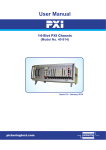
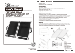
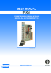
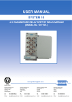
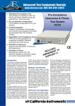
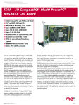
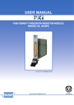
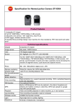
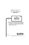
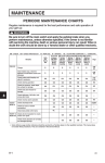
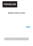
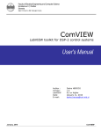
pickering
USER MANUAL
IEEE-488 / GPIB
SYSTEM 10 / 20 ANCILLARIES
(CASES, POWER SUPPLIES, EXPANSION CASES
& EXPANSION MODULES)
Issue 3.1 July 2008
pickering
www.pickeringtest.com
SYSTEM 10 / 20 ANCILLARIES MANUAL
ISO 9002
Reg No. FM38792
Page 1
pickering
© Copyright (2008) Pickering Interfaces. All Rights Reserved.
No part of this publication may be reproduced, transmitted, transcribed, translated or stored in any form, or
by any means without the written permission of Pickering Interfaces.
Technical details contained within this publication are subject to change without notice.
Page ii
SYSTEM 10 / 20 ANCILLARIES MANUAL
pickering
TECHNICAL SUPPORT
For Technical Support please contact Pickering Interfaces either by phone, fax, the website or via e-mail.
WARRANTY
All products manufactured by Pickering Interfaces are warranted against defective materials and workmanship for a period of two
years, excluding PXI chassis, from the date of delivery to the original purchaser. Any product found to be defective within this period
will, at the discretion of Pickering Interfaces be repaired or replaced.
Products serviced and repaired outside of the warranty period are warranted for ninety days.
Extended warranty and service are available. Please contact Pickering Interfaces by phone, fax, the website or via e-mail.
ENVIRONMENTAL POLICY
Pickering Interfaces operates under an environmental management system similar to ISO 14001.
Pickering Interfaces strives to fulfil all relevant environmental laws and regulations and reduce wastes and releases to the
environment. Pickering Interfaces aims to design and operate products in a way that protects the environment and the health and
safety of its employees, customers and the public. Pickering Interfaces endeavours to develop and manufacture products that can
be produced, distributed, used and recycled, or disposed of, in a safe and environmentally friendly manner.
Observe the Electrical Hazard Warning detailed in Section 9.
Observe the Electrostatic Sensitive Device Caution detailed in Section 9.
Worldwide Technical Support and Product Information
http://www.pickeringtest.com
Pickering Interfaces Headquarters
Stephenson Road Clacton-on-Sea CO15 4NL United Kingdom
Tel:
+44 (0)1255-687900
Fax:
+44 (0)1255-425349
E-Mail:
[email protected]
Pickering Interfaces Inc.
2900 Northwest Vine Street
Grants Pass
Oregon 97526
USA
Pickering Interfaces GmbH
Johann-Karg-Straße 30
D-85540
Haar-Salmdorf
Germany
Pickering Interfaces AB
Karl Nordströmsväg 31
432 53
Varberg
Sweden
Tel: +1 541 471 0700
Fax: +1 541 471 8828
E-Mail: [email protected]
Tel: +49 89 125 953 160
Fax: +49 89 125 953 189
E-Mail: [email protected]
Tel: +46 340-69 06 69
Fax: +46 340-69 06 68
E-Mail: [email protected]
Pickering Interfaces Inc.
(East Coast Regional Office)
12 Alfred Street Suite 300-3
Woburn Massachusetts 01801
USA
Pickering Interfaces s.r.o.
Smetanova 525
ˇ
Trinec
739 61
Czech Republic
Pickering Interfaces SARL
6 Rue De La Mare Blanche
77186 Noisiel
Marne Le Vallee
France
Tel: +1 781 897 1710
Fax: +1 781 897 1701
E-mail: [email protected]
Tel: +42 0558 339 168
Fax: +42 0558 340 888
E-mail: [email protected]
Tel +33 1 60 53 55 50
Fax +33 1 60 53 55 99
email [email protected]
SYSTEM 10 / 20 ANCILLARIES MANUAL
Page iii
pickering
THIS PAGE INTENTIONALLY BLANK
Page iv
SYSTEM 10 / 20 ANCILLARIES MANUAL
pickering
CONTENTS
Copyright Statement..............................................................ii
Technical Support and Warranty..........................................iii
Contents (this page)...............................................................v
Section 1
Enclosures...........................................................................1.1
Case Dimensional Data............................................1.1
System 10 Case Schematic Diagrams....................1.1
Mixed System 10/20 Case Schematic Diagrams....1.1
Section 2
System Backplanes.............................................................2.1
Overview....................................................................2.1
Backplane Layout.....................................................2.1
Section 3
Power Supplies....................................................................3.1
Features.....................................................................3.1
Power Supply Up/Down Sequencing Option..........3.1
Typical Driving Capability........................................3.1
Using External Power Supplies...............................3.1
Section 4
Expansion Cases and Modules..........................................4.1
Features.....................................................................4.1
Expansion Cases and Sub-Racks...........................4.1
Expansion Modules..................................................4.1
Section 5
Prototyping Modules...........................................................5.1
Features.....................................................................5.1
Section 6
Warnings and Cautions......................................................6.1
SYSTEM 10 / 20 ANCILLARIES MANUAL
Page v
pickering
THIS PAGE INTENTIONALLY BLANK
Page vi
SYSTEM 10 / 20 ANCILLARIES MANUAL
Section 1 - ENCLOSURES
pickering
SECTION 1 - ENCLOSURES
1.1 Features
●●
●●
●●
●●
●●
●●
●●
DIN 41494 (IEC297) compatible.
Compact Free standing case - case is also rack mountable Full rack width (84HP), available in heights of 3U or 6U.
Choice Of Module Access At Front Or Rear of Case
Includes complete system motherboard.
Expansion Cases Available
Accepts all System 10/20 switching modules.
Switching System Cases come in a variety of sizes and may be benchtop or rack mounted, with either front or
rear access versions to suit all cabling needs. Any combination of switching modules may be loaded into a case.
Expansion cases are available for larger systems.
All System 10/20 Cases come complete with pre-wired internal backplane and module guides to match the
configuration required, unused slots have blanking panels inserted. Interface and power supplies must be ordered
separately.
1.1.1 Front or Rear Access
All case types are available with a choice of front or rear switching module loading:
“Front Access Cases” are generally popular for smaller systems where the unit will be used on a benchtop, the
switching modules plug into the front of the case.
“Rear Access Cases” are usually more convenient for larger systems where a complete test or data acquisition
system is being assembled into a cabinet. The switching modules plug into the rear of the case, keeping all wiring
inside the cabinet, leaving the front panel uncluttered. This case version has a simple front panel with power indicator
as shown in Figure 1.6.
Front Access cases require power supply, type 10-910-001, while rear access type require type 10-910-002.
On both versions power enters at the rear of the case on an IEC connector.
1.1.2 Serviceability
All Pickering Interfaces case types are passive, they contain no active components. Therefore maintenance and
servicing can be done by simple module swapping, without having to remove the case.
1.1.3 Earth & Shielding Details
The whole case (all external surfaces) is earthed to the a.c. power ground. All plug-in modules earth by means of 2
or 4 earth bonding screws on their front panel.
For shielding purposes all switching modules have a shield connection point to be used with user constructed cable
assemblies. An earthing stud (M8) mounted on a 6HP panel suitable for a central earthing is available, type 10-942906.
In addition most modules have supplementary RFI screening, especially RF/Microwave types.
1.1.4 System 20 Modules
System 20 modules may be used within a mixed System 10/20 case, type 20-935A or 20-936A, please refer to
Section 1.4.
SYSTEM 10 / 20 ANCILLARIES MANUAL
Page 1.1
Section 1 - ENCLOSURES
pickering
1.1 Case Dimensional Data
All cases conform to DIN 41494 Part 5, IEC 297 Sec 2, see figs 1.2 and 1.3, for further dimensional data please
contact Pickering Interfaces.
Case Colour: Light Grey
Case Weight: Depends upon case size and number and type of modules being used, there are too many combinations
to list here, please contact factory to discuss.
Case Width: 449mm (not including rack mount brackets)
Case Height: 3U (133mm), 6U (266mm)
Case Depth: 250mm
Rack Mounting: Cases have built-in ears that can be pulled out when rack mounting is required.
Case Type: Vero Electronics KM7 II
For rear access case types allow extra space for switching module protruding connectors (possible up to 100mm).
10-930A-001
10-930A-002
10-934A-001
10-934A-002
3U Full Width Case, Front Access
3U Full Width Case, Rear Access
6U Full Width Case, Front Access
6U Full Width Case, Rear Access
Table 1.1 System 10 Case Order Codes
10-941-001
10-941-002
PCB Card Guide
Plug-In Module Card Guide
10-942-003
10-942-006
10-942-012
10-942-021
3HP Blanking Panel (3U)
6HP Blanking Panel (3U)
12HP Blanking Panel (3U)
21HP Blanking Panel (3U)
10-942-906
Earthing Stud (M8) on 6HP Panel (3U)
Table 1.2 System 10 Accessories Order Codes
Figure 1-1. System 10 Case 10-930A-001 Unloaded
Page 1.2
SYSTEM 10 / 20 ANCILLARIES MANUAL
Section 1 - ENCLOSURES
pickering
1.1 System 10 Case Schematic Diagrams
The following diagrams illustrate all case variants, showing how much switching module space is available for each
type. These will allow the most suitable case type to be selected. If your application exactly fills a case it may be
worth looking at the next size up, so that unforeseen requirements needing additional modules can easily be added
at a later date.
Other case sizes & options are available, please contact factory if you require further information.
449mm (17.7”)
IEEE-488.2
Interface
Power Supply
13.2” (66HP) of Panel Space Remaining for
Switching Modules
Figure 1-2. Full Width Single Height Case 10-930A-001 or 10-390A-002
Total of 30” (150HP) of Panel Space
Remaining for Switching Modules
Power Supply
IEEE-488.2
Interface
133mm
(5.25”)
427mm (16.8”)
Figure 1-3. Full Width Double Height Case 10-934A-001 or 10-934-002
SYSTEM 10 / 20 ANCILLARIES MANUAL
Page 1.3
Section 1 - ENCLOSURES
Figure 1-4. System 10 Front Access Case
Figure 1-5. System 10 Rear Access Case
Figure 1-6. 6U Rear Access System 10 Case, Viewed from front
Page 1.4
SYSTEM 10 / 20 ANCILLARIES MANUAL
pickering
Section 1 - ENCLOSURES
pickering
1.4 Mixed System 10/20 Case Schematic Diagrams
The 20-935A/936A Switching System Cases should be chosen when both System 10 and 20 switching modules are
required. The cases are suitable for both benchtop and rack mount use (hinged brackets are fitted to the case and
can be flipped out when required). They are supplied complete with pre-wired internal backplane and module guides
to match the configuration required, unused slots have blanking panels inserted.
The standard option for 6U cases is a split of 24/60 between System 10 and 20, however the case may be ordered
to match any combination of switching modules required by the customer.
3U cases do not have any split options and mix System 10 modules mounted vertically and System 20 modules
mounted horizontally. See Figure 1.10.
1.4.1 Case Schematic Diagrams
The following diagrams illustrate all case variants (types 20-935A and 20-936A) showing how much switching module
space is available for each type. These will allow the most suitable case type to be selected. If your application
exactly fills a case it may be worth looking at the next size up, so that unforeseen requirements needing additional
modules can easily be added at a later date.
The standard 6U cases are split 24/60 (see illustrations), many other configurations are available, for instance the
12/72 split shown. Please contact factory if you require further information.
20-935A-001
20-935A-002
6U System 10/20 Case, Front Access
6U System 10/20 Case, Rear Access
20-936A-001
20-936A-002
3U System 10/20 Case, Front Access
3U System 10/20 Case, Rear Access
Table 1.3 System 10/20 Case Order Codes
10-941-001
10-941-002
PCB Card Guide
Plug-In Module Card Guide
10-942-003
10-942-006
10-942-012
10-942-021
3HP Blanking Panel (3U)
6HP Blanking Panel (3U)
12HP Blanking Panel (3U)
21HP Blanking Panel (3U)
10-942-906
Earthing Stud (M8) on 6HP Panel (3U)
20-942-003
20-942-006
20-942-012
20-942-021
3HP Blanking Panel (6U)
6HP Blanking Panel (6U)
12HP Blanking Panel (6U)
21HP Blanking Panel (6U)
20-942-906
Earthing Stud (M8) on 6HP Panel (6U)
Table 1.4 System 20 Accessories Order Codes
SYSTEM 10 / 20 ANCILLARIES MANUAL
Page 1.5
Section 1 - ENCLOSURES
pickering
449mm (17.7”)
13.2” (66HP) of
System 10 Panel Space
Remaining
8.4” (42HP) of System 20
Panel Space Remaining
Power Supply
266mm
IEEE-488.2
Interface
427mm (16.8”)
IEEE-488.2
Interface
Figure 1-7. System 10/20 Case Split 42/42 (20-935A-001-42/42 or 20-935A-002-42/42)
Power Supply
14.4” (72HP) of System 20
Panel Space Remaining
Power Supply
IEEE-488.2
/RS-232
Figure 1-8. System 10/20 Case Split 12/72 (20-935A-001-12/72 or 20-935A-002-12/72)
6” (30HP) of
System 10
Panel Space
Remaining
12” (60HP) of System 20
Panel Space Remaining
Figure 1-9. System 10/20 Case Split 24/60 (20-935A-001-24/60 or 20-935A-002-24/60)
Page 1.6
SYSTEM 10 / 20 ANCILLARIES MANUAL
Section 1 - ENCLOSURES
pickering
449mm (17.7”)
IEEE-488.2
/RS-232
Power Supply
133mm
(5.25”)
427mm (16.8”)
2.4”
(12HP) of
System
10 Panel
Space
3.6” (18HP) of System 20
Panel Space (Horizontally
Mounted Switching Modules)
Figure 1-10. Full Width Single Height System 10/20 Case (20-936A-001 or 20-936A-002)
Figure 1-11. System 10/20 Front Access Case Split 24/60
Figure 1-12. System 10/20 Front Access Case Split 12/72
SYSTEM 10 / 20 ANCILLARIES MANUAL
Page 1.7
Section 1 - ENCLOSURES
Figure 1-13. Mixed System 10/20 Front Access Case (Split 42/42)
Figure 1-14. 3U Mixed System 10/20 Front Access Case
Page 1.8
SYSTEM 10 / 20 ANCILLARIES MANUAL
pickering
Section 2 - SYSTEM BACKPLANES
pickering
SECTION 2 - SYSTEM BACKPLANES
2.1 Overview
All System 10/20 cases have a standard backplane which provides power, digital communications and a 10 pole
analogue bus to all switching modules.
Switching modules may be placed anywhere on the backplane (i.e. they are not position dependant). Each module
slot has a DIN 41612 64 way connector. All slots are arranged on a 0.6 Inch pitch.
There are 10 slots in the half width case and 24 slots in the full width case. Maximum number of modules per
backplaneis 20.
2.2 Backplane Layout
2.2.1 Power Supply
Provides the three voltage supplies to all System 10 modules.
2.2.2 System Digital Bus
This is the internal bus used to communicate with all System 10 modules. It has a “Master/Slave” configuration with
the GPIB/RS-232 interface module being the master.
Note: The communication bus is actually a direct implementation of the IEEE-488 bus put onto the backplane 64
way connectors. Recent modules use a high speed proprietary serial bus with a built in error checking/correction
protocol.
2.2.3 Analogue Bus
Used by multiplexer and matrix modules to carry analogue signals. System 10 has a 10 line shielded bus, System
20 has the 10 pole bus plus a further 24 pole shielded bus. An optional high density 128 pole analogue bus is
available (20-943) for use with the 20-630 multiplexer series.
2.2.4 Workspace Area
This area is available to the user for use in custom interconnection between modules. It is only suitable for voltages
<100V & current <1.5A. Modules which currently have access to this are model series : 10-600 and 10-200.
2.2.5 Backplane Connector
Type: DIN 41612 type socket.
No. of contacts:
64 (160 for high density backplane type 10-943).
Rated number of insertions:
400.
SYSTEM 10 / 20 ANCILLARIES MANUAL
Page 2.1
Section 2 - SYSTEM BACKPLANES
pickering
ROW
A
C
GND
5V(relay)
5V(logic)
DIO1
DIO3
EOI
NRFD
IFC
ATN
DIO5
MOSI/DIO7
REN
Settled
-FSS
Analogue 1.1
Analogue 1.2
Analogue 1.3
Analogue 1.4
Analogue 1.5
Analogue 1.6
Analogue 1.7
Analogue 1.8
Analogue 1.9
Analogue 1.10
Slot Address Bit 0
Slot Address Bit 2
Slot Address Bit 4
Backplane Address Bit 1
12V(relay)
5V(logic)
GND
1
2
3
4
5
6
7
8
9
10
11
12
13
14
15
16
17
18
19
20
21
22
23
24
25
26
27
28
29
30
31
32
GND
12V(relay)
POWER SUPPLIES
5V(logic)
DIO2
DIO4
DAV
NDAC
SRQ
Reserved
Parallel and Serial Bus
DIO6/MISO
DIO8/SCK
Reserved
-SS
Reserved
Analogue 1.1
Analogue 1.2
Analogue 1.3
Analogue 1.4
Analogue 1.5
ANALOGUE BUS
Analogue 1.6
Analogue 1.7
Analogue 1.8
Analogue 1.9
Analogue 1.10
Slot Address Bit 1
Slot Address Bit 3
POSITION
Backplane Address Bit 0
LOCATOR
Backplane Address Bit 2
12V(relay)
5V(logic)
GND
POWER SUPPLIES
Figure 2-1. System 10/20 Backplane Pin Connections
(Power, Communications and 10 Pole Analogue Bus)
Page 2.2
SYSTEM 10 / 20 ANCILLARIES MANUAL
Section 2 - SYSTEM BACKPLANES
pickering
Analogue 2.1
Analogue 2.2
Analogue 2.3
Ground
Analogue 2.4
Analogue 2.5
Analogue 2.6
Ground
Analogue 2.7
Analogue 2.8
Analogue 2.9
Ground
Analogue 2.10
Analogue 2.11
Analogue 2.12
Ground
Analogue 2.13
Analogue 2.14
Analogue 2.15
Ground
Analogue 2.16
Analogue 2.17
Analogue 2.18
Ground
Analogue 2.19
Analogue 2.20
Analogue 2.21
Ground
Analogue 2.22
Analogue 2.23
Analogue 2.24
Ground
ROW
A
C
1
2
3
4
5
6
7
8
9
10
11
12
13
14
15
16
17
18
19
20
21
22
23
24
25
26
27
28
29
30
31
32
Analogue 2.1
Analogue 2.2
Analogue 2.3
Ground
Analogue 2.4
Analogue 2.5
Analogue 2.6
Ground
Analogue 2.7
Analogue 2.8
Analogue 2.9
Ground
Analogue 2.10
Analogue 2.11
Analogue 2.12
Ground
Analogue 2.13
Analogue 2.14
Analogue 2.15
Ground
Analogue 2.16
Analogue 2.17
Analogue 2.18
Ground
Analogue 2.19
Analogue 2.20
Analogue 2.21
Ground
Analogue 2.22
Analogue 2.23
Analogue 2.24
Ground
Figure 2-2. System 20 Standard 24 Pole Analog Bus Backplane Pin Connections
SYSTEM 10 / 20 ANCILLARIES MANUAL
Page 2.3
Section 2 - SYSTEM BACKPLANES
pickering
ROW
A B C D E
1
2
3
4
5
6
7
8
9
10
11
12
13
14
15
16
17
18
19
20
21
22
23
24
25
26
27
28
29
30
31
32
Shield Ground (A1 to A32)
Analog Bus 1 to 32 (B1 to B32)
Analog Bus 33 to 64 (C1 to C32)
Analog Bus 65 to 96 (B1 to B32)
Analog Bus 97 to 128 (B1 to B32)
Figure 2-3. System 20 High Density 128 Pole Analog Bus Backplane Pin Connections Model 20-943-001
(160 Way Reversed DIN 41612)
Page 2.4
SYSTEM 10 / 20 ANCILLARIES MANUAL
Section 3 - POWER SUPPLIES
pickering
SECTION 3 - POWER SUPPLIES
3.1 Features
●●
●●
●●
●●
●●
Triple output 100W DC power supply.
Low noise highly efficient secondary switcher.
Power trading provides flexible outputs.
Univeral voltage operation, between 100V and 250V AC
Front panel LED indicators.
Input Voltages:
100V AC to 250V AC (45 - 65 Hz).
Outputs:
Triple outputs with maximum total power 100W. Refer to Table 3.1 for current capacity.
Output
Voltage
Nominal
Current
Continuous
Current
Peak
Current
+5V logic supply
+5V relay supply
+12V relay supply
4.0A
3.0A
2.0A
7.0A
7.0A
3.0A
10.0A
10.0A
5.0A
Table 3.1 Power Supply Output Current Capacity
Isolation:
4kV input to output
Environment:
0-70°C, Derate by 2.5% per °C above 45°C.
Connector:
DIN 41612 type H.
Weight:
10-910-001: 1.45Kg approx.
10-910-002: 1.70Kg approx.
Safety Specifications: IEC 380, IEC 435, BS 5850, BS 6301, VDE 0804, VDE 0806, UL 478 & CSA 22.2.
Model 10-910A-001
Suitable for front panel mounting, 12HP wide:
Use this model with cases: 10-930-001, 10-934-001, 20-935-001, 20-936-001
Model 10-910A-002
Suitable for rear panel mounting, 12HP wide:
Includes mains socket/filter & on/off switch.
Use this model with cases: 10-930-002, 10-934-002, 20-935-002, 20-936-002
SYSTEM 10 / 20 ANCILLARIES MANUAL
Page 3.1
Section 3 - POWER SUPPLIES
pickering
3.2 Power Supply Up/Down Sequencing Option
This provides controlled sequencing of the three power supplies during mains on and off, particularly useful for
unexpected mains fail and restore. This feature will prevent any possibility of unstable 5V logic momentarily operating
relay coils.
Power Up Sequence
Delays connection of the two relay supplies (+5V & +12V) for approximately 3 seconds, thus allowing the logic on
all switching modules to power up to a known state before applying relay power supplies - softstart is applied to the
12 Volt line.
Power Down Sequence
Upon sensing a mains fail (due either to turning off power switch or a direct mains fail) the two relay supply voltages
are disconnected and immediately crowbarred (i.e. connected to ground through a low impedance path).
This feature is tolerant of mains failures below approximately 10ms (i.e. half of 50Hz cycle). Typical tolerance will
be somewhat longer, however this will be very dependent upon power supply loading.
The Power Up/Down Sequencing function is fitted to all on all System 10/20 power supplies.
3.3 Typical Driving Capability
This power supplies will typically drive in excess of 20 switching modules, i.e. this will run all but the largest
switching systems. However this will vary depending upon module type and the maximum number of relays to be
simultaneously operated. The table below gives an indication of module power consumption. If in the unlikely event
of approaching or exceeding the 100W power limit the preferred approach is to split the system into two cases
joined with a pair of expansion modules (this will be software transparent).
Module
Description
Module State
Typical Power
Max No. Per Case
10-921
IEEE-488.2
—
1W
—
10-115
Reed Relay Module
All Relays Off
8 Relays On
0.6W
2.3W
>30
>30
10-410
Digital I/O Module
—
1.3W
>30
10-530
8x8 Matrix
0 Crosspoints On
8 Crosspoints On
0.8W
2W
>30
>30
10-740-
RF Multiplexer
2 Channels On
1.5W
>30
20-510
20x8 Matrix
0 Crosspoints On
8 Crosspoints On
20 Crosspoints On
0.8W
2W
3W
>30
>30
25
20-310
High Volts Module
8 Relays On
3W
25
Table 3.2 Power Supply Typical Driving Capability
Page 3.2
SYSTEM 10 / 20 ANCILLARIES MANUAL
Section 3 - POWER SUPPLIES
pickering
Figure 3-1. 10-910A-001 Power Supply
Figure 3-2. 10-910A-002 Power Supply
3.4 Using External Power Supplies
In OEM applications it may be required to operate the switching system from an external DC power supply. However
it is very important that the logic supply be kept completely separate from the voltage supply used to drive the relay
coils, especially when using power or high voltage relays, in addition sequencing of these two supplies is important
at power on and off. For further information please contact factory.
d
4
6
8
10
12
14
16
18
20
22
24
26
28
30
32
b
z
d
+5V Logic
+5V Logic
Ground
Ground
Reserved
(Power Fail - TTL)
+12V Relay
+5V Relay
(res cap)
Not Used
Neutral
Internal Connection
Internal Connection
Live (100-250V AC r.m.s.)
Earth
b
z
+5V Logic
+5V Logic
4
6
Ground
Ground
8
10
Reserved
(Power Fail - TTL)
+12V Relay
+5V Relay
(res cap)
12
14
16
18
20
not used
22
24
not used
Internal Connection
Internal Connection
26
28
30
32
not used
Earth
Figure 3-3. 10-910A-001 Power Supply
Internal Connector
Figure 3-4. 10-910A-002 Power Supply
Internal Connector
(DIN 41612 Type H15))
(DIN 41612 Type H15))
SYSTEM 10 / 20 ANCILLARIES MANUAL
Page 3.3
Section 3 - POWER SUPPLIES
THIS PAGE INTENTIONALLY BLANK
Page 3.4
SYSTEM 10 / 20 ANCILLARIES MANUAL
pickering
Section 4 - EXPANSION CASES AND MODULES
pickering
SECTION 4 - EXPANSION CASES AND MODULES
4.1 Features
If the number of modules you require does not fit within a standard case or if you wish to split the switching system
into two or more cases (e.g. to keep high voltage modules away from low voltage types) then you will need to use
type the 10-925 expansion module.
The case with the IEEE-488 interface module acts as the master with all other cases acting as slaves. Each case
must contain a it’s own power supply unit plus expansion module/s. Expansion modules must be used in pairs,
the expansion cable linking them can be ordered to the length required. The limit of 20 modules per System 10/20
master rack should still not be exceeded.
Reasons for using Expansion Racks
●●
●●
●●
Main rack overflow.
To keep noisy switching modules away from the main case (e.g. high voltage switching).
To keep individual switching modules as close to the load being switched as possible (e.g. RF Switching)
4.2 Expansion Cases & Sub-Racks
Expansion cases and sub-racks have the same order codes as the standard versions, refer to Section 1, each case
requires it’s own power supply and expansion module. For particular requirements the power supply from the master
case may be used (please contact factory to discuss your application).
4.3 Expansion Modules
To connect an expansion case to the main case you will have to have use a pair of expansion modules, one in
each rack. The expansion module carries all module digital communications (and power supplies for specialised
requirements), but NOT the internal Analogue Buses.
If your slave case does not have it’s own power supply then please consider the power supply requirements of the
expansion case (it should not exceed 45W), if in doubt please contact factory to discuss your application. All power
supplies are decoupled and have limited transient protection, but if noisy signals are being switched then a separate
power supply may be needed.
Expansion module (10-925-001) has a front panel mounted 37 way D-type female connector, the two modules must
be linked by the 10-953-020 expansion cable assembly (available in various lengths, 2m is standard). A pin out
diagram is shown in Fig 4.1.
10-925-001
System 10/20 Expansion Module
10-953-020
Expansion Cable Assembly (2m length)
Other cable lengths may be specified,
e.g.. -010 = 1m, -005 = 0.5m.
Expansion Modules must be used in pairs.
Table 4.1 Expansion Module Order Codes
SYSTEM 10 / 20 ANCILLARIES MANUAL
Page 4.1
Section 4 - EXPANSION CASES AND MODULES
Not Connected (5V rly) †
Not Connected (12V rly) †
Not Connected (5V log) †
Ground
Ground
Analogue 1.5
Analogue 1.4
Analogue 1.3
Analogue 1.2
Analogue 1.1
S. Bus Clock (A14)
S. Bus (C14)
Settled (A13)
S Bus Data (C13)
Reserved (C12)
Reserved (C9)
37
36
35
34
33
32
31
30
29
28
27
26
25
24
23
22
Ground
21
Ground
20
19
18
17
16
15
14
13
12
11
10
9
8
7
6
5
4
3
2
1
pickering
Not Connected (5V rly) †
Not Connected (12V rly) †
Not Connected (5V log) †
DIO2
DIO1
DIO4
DIO3
DAV
NDAC
NRFD
IFC
† Each expansion case usually has itʼs own power
supply, but power can be carried from the master to
the slave case for applications with low power
requirements (consult factory for further information).
ATN
DIO6
DIO5
DIO8
DIO7
SRQ
EOI
REN
Figure 4-1. Expansion Connector Pin-Out
Page 4.2
SYSTEM 10 / 20 ANCILLARIES MANUAL
Section 5 - PROTOTYPING MODULES
pickering
SECTION 5 - PROTOTYPING MODULES
5.1 Features
Prototyping modules are available for users to construct their own circuitry in. They consist of a fully screened
module with a blank front panel and internal stripboard with built on DIN 41612 connector.
These modules are based on Vero Electronics type KM6 II, further dimensional information is available in their
catalogue.
Users working with these modules may have to re-work the blank front panel to suit their own connector requirements.
Pickering Interfaces have a range of Breadboard modules with built in drive circuitry and front panel connectors
(model types 10-210 and 10-220).
System 10 Prototyping Modules are available in three sizes
10-944-012
2.4 Inch Front Panel Width 12HP (3U)
10-944-024
4.8 Inch Front Panel Width 24HP (3U)
10-944-042
9.6 Inch Front Panel Width 42HP (3U)
System 20 Prototyping Modules are available in three sizes
20-944-012
2.4 Inch Front Panel Width (12HP, 6U)
20-944-024
4.8 Inch Front Panel Width (24HP, 6U)
20-944-042
9.6 Inch Front Panel Width (42HP, 6U)
Figure 5-1. System 10 Prototype Module Exploded View
SYSTEM 10 / 20 ANCILLARIES MANUAL
Page 5.1
Section 5 - PROTOTYPING MODULES
pickering
Figure 5-2. System 10 Prototype Module Top and Bottom Screen Positioning
Figure 5-3. System 10 Prototype Module Side Screen Positioning
Page 5.2
SYSTEM 10 / 20 ANCILLARIES MANUAL
pickering
Section 6 - WARNINGS & CAUTIONS
SECTION 8 - WARNINGS & CAUTIONS
WARNING - DANGER OF ELECTRIC SHOCK
THESE MODULES CONTAIN HAZARDOUS VOLTAGES. BEFORE REMOVING
THE outer Covers REMOVE ALL SUPPLIES.
CAUTION
Handling of Electrostatic-Sensitive Semiconductor Devices
Certain semiconductor devices used in the equipment are liable to damage due to static
voltage. Observe the following precautions when handling these devices in their
unterminated state, or sub-units containing these devices:
(1) Persons removing sub-units from an equipment using these devices must
be earthed by a wrist strap and a resistor at the point provided on the equipment.
(2) Soldering irons used during the repair operations must be low voltage types
with earthed tips and isolated from the mains voltage by a double insulated
transformer.
(3)
Outer clothing worn must be unable to generate static charges.
(4) Printed Circuit Boards (PCBs) fitted with these devices must be stored and
transported in anti-static bags.
SYSTEM 10 / 20 ANCILLARIES MANUAL
Page 8.1
pickering
THIS PAGE INTENTIONALLY BLANK
Page 8.2
SYSTEM 10 / 20 ANCILLARIES MANUAL