1
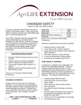
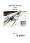
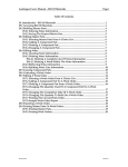
DIGITAL OIL PRESET METER
OWNER’S MANUAL
WARNING: Read carefully and understand all
INSTRUCTIONS before operating. Failure to follow the safety
rules and other basic safety precautions may result in serious
personal injury.
Item #181335
INTENDED USE
Oil preset meter can be used to dispense motor oil. With the pre-selected function, the nozzle
automatically closes the valve and stops dispensing.
TECHNICAL SPECIFICATIONS
Flow Range
0.3-9.2 GPM
Operating Pressure Range
7-1000 PSI
Operating Temperature
Max. 140°F
Accuracy
±5%
Viscosity
8-5000 mPas
5-Digital LCD Display
Quart, Pint, Gallon, Liter
(3/8"H x 3/16"W)
Inlet Connection
1/2"
Power Source
4 AA size 1.5V Batteries
*Tested with DTE-25 motor oil at ambient temperature. Min.-Max. flow range will vary with fluid
viscosity.
GENERAL SAFETY RULES
WARNING: Read and understand all instructions. Failure to follow all instructions listed
below may result in electric shock, fire and/or serious injury.
WARNING: The warnings, cautions, and instructions discussed in this instruction
manual cannot cover all possible conditions or situations that could occur. It must be understood
by the operator that common sense and caution are factors which cannot be built into this product, but
must be supplied by the operator.
SAVE THESE INSTRUCTIONS
WORK AREA
•
Keep work area clean, free of clutter and well lit. Cluttered and dark work areas can cause
accidents.
•
Do not use your meter where there is a risk of causing a fire or an explosion; e.g. in the
presence of flammable liquids, gasses, or dust. Power tools create sparks, which may ignite the
dust or fumes.
•
Keep children and bystanders away while operating this meter. Distractions can cause you to
lose control, so visitors should remain at a safe distance from the work area.
Page 2 of 20
•
Be aware of all power lines, electrical circuits, water pipes and other mechanical hazards in
your work area, particularly those hazards below the work surface hidden from the operator’s
view that may be unintentionally contacted and may cause personal harm or property damage.
•
Be alert of your surroundings. Using tools in confined work areas may put you in danger.
PERSONAL SAFETY
•
Stay alert, watch what you are doing and use common sense when operating this meter. Do not
use this meter while you are tired or under the influence of drugs, alcohol or medication. A
moment of inattention while operating this meter may result in serious personal injury.
•
Dress properly. Do not wear loose clothing, dangling objects, or jewelry. Keep your hair, clothing
and gloves away from moving parts. Loose clothes, jewelry or long hair can be caught in moving
parts. Air vents often cover moving parts and should be avoided.
•
Use safety apparel and equipment. Use safety goggles or safety glasses with side shields
which comply with current national standards, or when needed, a face shield. This applies to all
persons in the work area. Also use non-skid safety shoes, hardhat, gloves, dust collection
systems, and hearing protection when appropriate.
•
•
•
•
•
•
•
Do not overreach. Keep proper footing and balance at all times.
The meter is for professional use only.
Read all instructions, tags, and labels before operating the meter.
Use the meter only for its intended purpose.
Do NOT stop or deflect leaks with hands, body, gloves, or rags.
Do NOT dispense valves toward any person or any part of the body.
Do NOT place hands or fingers over the end of or into the dispense valve.
FACTORY SETTINGS
•
Each meter is preprogrammed and calibrated at the factory. Unless otherwise specified at the
time of order, each meter is programmed in quarts for use with motor oil as standard. The meter
is shipped in the Manual Mode.
•
The factory preset cannot be changed; if special requirements are needed, please contact an
authorized service center.
TOOL USE
•
•
•
•
•
•
DO NOT modify or alter the meter.
DO NOT leave the meter unattended while dispensing.
Check the meter daily. Worn or damaged parts should be repaired or replaced immediately.
DO NOT exceed the maximum working pressure level of the lowest rates system component.
Use only extensions and nozzles that are compatible with this meter.
Use only fluids and solvents that are compatible with the equipment. Notice the warnings for fluids
and solvents.
•
•
•
Tighten all fluid connections before operating the meter.
Comply with all local, state, and federal fire, electrical and safety regulations.
Use of the product in a manner other than specified in this manual may result in bodily injury or
impaired operation or damage to the meter.
Page 3 of 20
OPERATION
The Digital Meter requires 4 AA (1.5V) batteries to operate (batteries included). For battery replacement,
refer to Section D, Battery Replacement elsewhere in this manual.
1. Keypad Buttons
Press to enter the quantity to be dispensed.
AUTO
Press to enter and exit the AUTO Mode.
RESET
Press in Manual or AUTO Mode to clear the previously
programmed batch and to reset the meter.
OK/STOP
Press to confirm the Valve and to stop the flow through
a mechanical override.
2. INSTALLATION
A. Pre-installation Procedure
1)
Relieve the system pressure
a) Turn off the power supply to the pump or close the shutoff valve.
b) Dispense any fluid in the system into a waste container by opening the dispense valve.
c) Open all bleed-type master air and fluid drain valve in the system.
d) Leave the drain valve open until ready to pressurize the system.
2)
Close the shutoff valve.
3)
Ground hoses and reels:
Grounding reduces the risk of static sparking; ground all system components according to local,
state, and federal codes. Consult the user’s manual on the pump and other system components to
ground the following:
a) Pump: follow manufacturer’s recommendations.
b) Air and fluid hoses: use only grounded hoses.
c) Air compressor: follow manufacturer’s recommendations.
d) Fluid supply container: follow the local code.
WARNING
Do not use Teflon tape on pipe joints; it may cause a loss of grounding across the
joint.
Page 4 of 20
B. Installation Procedure
1)
2)
3)
4)
5)
If the Meter is installed, go directly to step 6. Steps 2 through 5 are for flushing the system prior to
installing the meter.
Close fluid dispensing valves at every dispensing position.
Once the main fluid outlet valve at the pump is closed, the air pressure to the pump motor is
properly adjusted, and the air valve is open, slowly open the main fluid valve.
Place the hose end in a waste container. Make sure hose is secure in order to ensure no fluid
leakage.
Open the dispense valve slowly and allow enough oil to pass through to ensure the system clean.
Note: If the system has multiple dispensed positions, start at the position farthest from the pump,
and move toward the pump.
6) Relieve the pressure (refer to Relieve the system pressure, above).
7) Insert the metal end of the hose into the swivel location at the end of the handle; tighten it
completely with an open-ended adjustable wrench.
Connecting the hose
8)
Note: The meter thread is always female, so the thread for the hose should be male. Apply thread
sealant to the male end. The inlet and outlet connections are 1/2" NPT or 1/2" BSPT, depending on
meter model.
Thread the new nozzle into the opposite end of the meter and screw it tightly with an open-ended
adjustable wrench.
Installing the nozzle
9) Open all dispense position shut-off valves, and start the pump to pressurize the system.
10) To ensure accuracy, purge all air from the fluid lines and dispense valve before use.
3. OPERATING THE METER
Page 5 of 20
WARNING
After using the manual anti-drip valve, it is important to
discharge the pressure between the chambers (1) and the
manual valve (2) of the spout. First, the pump must be
switched off. Then, unscrew the tip of the valve (2). During
this discharging operation, do not use the trigger (3).
To access the various customizing functions and to select the desired options, two different actions
are indicated on the keys.
z
z
This symbol indicates that it is necessary to press
briefly, and afterwards release it.
This symbol indicates that it is necessary to press
and hold on the key for a few
seconds.
To exit from the customization menu, independent of the activity in progress, press
displayed at that moment immediately become operational.
A. Display Mode
Start up the Meter by selecting
The Meter displays:
Last amount dispensed
Page 6 of 20
. The settings
Stored value Total
Press and hold
until the counter reads zero.
The Meter will display:
Reset Batch Total
Stored value Total
WARNING
The stored value total is set as a default in the factory and cannot be changed. If you need to
change it, please contact an authorized service center.
Pull the trigger to dispense.
Release the trigger to stop dispensing.
B. Operation Mode
B-1. Manual Mode
Program the Meter to Manual Mode by selecting
The Meter displays:
Manual Mode
Pull the trigger to begin the flow. When the desired amount has been pumped, release the trigger to
stop the flow.
Page 7 of 20
Press
to reset counter display to zero.
B-2. AUTO Mode
Meter stores:
1-2-3-4-last: Five different PRESET values which are frequently used.
Start up the Meter by selecting
Press
as many times as necessary to reach the desired values and the values are repeated.
Blinking message will be:
To confirm a PRESET value, press and hold
until the Meter displays:
Page 8 of 20
Reset Batch Total
AUTO message
not blinking
Selected value
To start dispensing, pull the trigger completely, then release.
The trigger thus remains locked in open position. Now dispensing can continue in AUTO mode.
Automatic stop
The flow automatically stops when the preset value is reached.
NOTE: If you want to stop dispensing before the preset value is reached, just press
stop.
WARNING
to
In all cases the operator must attend to the Meter while dispensing in AUTO
mode in order to avoid any oil spillage.
B-3. User Mode
If the Meter is off, press
to re-start it.
The value is last amount dispensed, the Meter will display:
Stored Value Total
To select a new PRESET value (for example, 12.3), press the numeric keys as many times as needed;
this value will be LAST mode automatically.
Page 9 of 20
The Meter displays:
Select value
Press
and hold until the counter turns to zero.
Reset Batch Total
Selected value
To start dispensing, pull the trigger completely, then release. The flow automatically stops when the
preset value is reached.
NOTE: If you want to stop dispensing before the preset value is reached, just press
stop.
to
C. Preset Values Setting
C-1. Numeric Function
Press and hold on
to set the function
Selective key
Numeric keys
Confirm and quit key
Press and hold on
to set the function: it contains Value setting (C-2), Unit setting (C-3),
Decimal Digits setting (C-4), Reset setting (C-5), Auto reset setting (C-6) and Calibrating setting (C-7).
Page 10 of 20
C-2. Value Setting
The Meter allows the Operator to store 5 different PRESET values (AUTO 1...AUTO 4), which can be
recalled without having to set them each time with the numeric keys.
Press and hold
once to set the function.
The Meter will display:
Blinking
Index of the PRESET value AUTO 1
When the value is blinking, press
value.
to select preset 1-4, then press the numeric buttons to set the
Blinking message will be:
Press
to confirm the value and quit the setting mode, the setting value will be stored.
By holding on the keys the value continues to vary.
C-3. Unit Setting
The Meter allows the user to select one of the following measurement Units:
•
•
•
•
QTS =
PTS =
LIT =
GAL =
QUARTS
PINTS
LITERS
GALLONS (U.S. Gallons)
Press and hold
two times to set the function.
The Meter displays:
Page 11 of 20
When the unit is blinking, press
Press
to select unit L, GAL, PT or QT.
to confirm the value and quit the setting mode, the setting value will be stored.
NOTE: The above mentioned measurement units refer to the Batch total indicators.
If you select the unit LITERS, the TOTALS will be displayed in LITERS.
If you select the unit GALLONS, PINTS or QUARTS, the TOTALS will be displayed in GALLONS.
The modification of the measurement unit does NOT require a new calibration.
If the TOTAL indicates a value other than zero, this value is automatically converted from one unit to
another unit.
z
z
z
z
C-4. Decimal Digits Setting
Press and hold
three times to set the function.
Blinking point
When the number point is blinking, press
decimal digits setting.
Press
to select location of the point to confirm the number of
to confirm the value and quit the setting mode. The setting value will be stored.
NOTE:
•
•
The Meter displays the FLOATING POINT Batch total dispensed.
Independent of the selection carried out (two or three decimal digits), as soon as the amount
dispensed exceeds 10 units, the Meter displays only two decimal digits.
•
As soon as the amount dispensed exceeds 99 units, the Meter displays only one decimal digit.
Page 12 of 20
C-5. Reset Setting
Press and hold
four times to set the function.
The Meter displays:
Blinking
When YES is blinking, press
to select YES or No. If YES the batch total will be set to zero after
hold
button for 10 seconds, NO to cancel.
Press
to confirm the value and quit the setting mode. The setting value will be stored.
NOTE: Independent of the selection carried out, the Batch Total supplied is never reset if the
dispensing operation has been carried out in AUTO mode.
C-6. Auto Reset Setting
The function described in this paragraph concerns only those who want to obtain the maximum
dispensing stop precision in AUTO mode.
If a slight excess of the pre-set value (a few hundredths of a quart) does not cause any problem, the
following paragraphs can be ignored.
The Meter in AUTO mode allows the user to obtain a highly precise stop, thus dispensing exactly the
pre-set amount without exceeding the PRESET value.
To guarantee this high stop precision, especially when the unit operates at the maximum allowed
flow rates, dispensing does not stop when the PRESET value is reached, but instead when the
PRESET value reaches a few Unit hundredths.
To guarantee the stop precision, this pre-stop value must not be fixed, but is dependent on the flow
rate used. To allow the operator to obtain the highest stop precision, the unit is equipped with a Stop
Precision factor, called PS factor.
Page 13 of 20
The operator can customize the Meter to select a PS factor between ZERO and FOUR.
By selection:
PS=0
a pre-closing equal to ZERO is set.
PS=1
PS=2
PS=3
PS=4
the MAXIMUM pre-closing is set.
Press and hold
five times to set the function.
The METER displays:
`
When PS factor is blinking, press
Blinking
to select PS 0-4 to increase the PS factor by one unit.
Blinking
Press
to confirm the value and quit the setting mode. The setting value will be stored.
NOTE: The higher the flow rate, the higher the selected PS value. If you select too high a PS value,
the dispensed amount may be lower than the pre-set value by some hundredths of a quart.
C-7.Calibrating Setting
The Meter is equipped with high-precision gears, pre-calibrated in the factory.
Why calibrate?
If the METER is used:
•
With fluids having a viscosity close to the limits of the allowed range (such as low-viscosity
antifreeze fluids or high-viscosity oils for gear boxes).
Page 14 of 20
•
In extreme flow rate conditions (close to the min. and max. value of the allowed range), it may
be necessary to carry out an on-site calibration.
How to calibrate
The Meter allows the user to carry out a rapid electronic calibration by modifying the Calibration factor
(K Factor).
At delivery all meters are given the same calibration factor:
K Factor = 1.000
This calibration factor guarantees the best accuracy in the following operating conditions:
Fluid:
Motor oil type 10W 30
Temperature: 68°F
Flow-rate:
2.6 GPM
The calibration can be done either as:
An on-site calibration by dispensing into a calibrated container or
A direct modification of the calibration factor.
z
z
On-site calibration by dispensing into a calibrated container:
Press and hold down
six times to set the function.
The METER displays:
Blinking
Press
; start the calibration by dispensing the fluid into a calibrated container.
During dispensing the Meter displays:
Batch Total dispensed
Blinking
Page 15 of 20
The dispensing operation may be interrupted and resumed.
The calibrated dispensing is complete when the level of the fluid reaches the graduated area of the
calibrated container.
Indicated value
Blinking
WARNING In order to get a correct Calibrated K Factor from the meter, ensure calibration
capacity is set to more than 5 quarts. Purge all air from the unit before carrying out the calibration.
Carry out the calibration dispensing at a steady flow rate by pulling the trigger completely and
keeping it in the open position until the container is nearly full. Do not reduce the flow rate to reach the
graduated area of the calibrated container. Instead, to complete the final stages of the filling operation
into the calibrated container, top-off in small increments. This is achieved by rapidly pulling the trigger of
the Meter and then releasing it very quickly.
Press
again to modify the value to equal the volume of the calibrated container.
Press key “10” to increase the indicated value.
Press key “0.1” to decrease the indicated value.
WARNING
After dispensing, wait a few minutes to allow any air bubbles in the calibrated container to dissipate.
Page 16 of 20
Verify the actual amount dispensed in the calibrated container; as the air bubbles dissipate, the
indicated level may decrease. Do not wait more than 15 minutes as the Meter will exit from the
menu and it will no longer be possible to complete the calibration operation.
The Meter is ready to accept the modification of the indicated value to correspond to the real value. A
key each time is pressed, the last digit on the right is modified under one unit.
After correction:
Press
again, the Meter will calculate the K Factor automatically which is blinking.
The Meter stores the new Calibration Factor (K Factor) and displays:
Blinking New K Factor
After a few seconds, the Meter automatically exits from the customization mode and starts using the
new Calibration Factor.
One dispensing operation is enough to carry out the on-site calibration of the meter.
If you wish to verify the result of this calibration, complete a normal dispensing in the same
Calibrated Container without re-entering the calibration function in the Customization menu.
D. Battery replacement
The Meter continuously controls the battery charging state. As soon as the battery level drops below a
Page 17 of 20
given level, the Meter displays:
Blinking message “bAtt”
As soon as the message “bAtt” appears, displaying in AUTO mode is immediately stopped and
it is no longer possible to lock the trigger in open position.
This prevents the unit from continuing to dispense in AUTO mode, even if the PRESET value has been
reached, because of an insufficient battery charge.
Even when the message “bAtt” is displayed, it is still possible to carry out dispensing
operations in MANUAL mode.
Although it is possible to carry out multiple dispensing operations in MANUAL mode even when the
message “bAtt” is being displayed, the batteries must be replaced as soon as possible to resume
the full functioning capacity of this METER and to avoid the quality of the image on the LCD from
deteriorating, thus causing metering errors.
When the message “bAtt” blinks, the TOTAL is constantly updated, although not displayed.
To replace the batteries:
1. With a small Phillips screwdriver, loosen the four screws of the battery pack and remove it.
2. Open the battery pack by removing the cover.
3. Remove the used batteries.
4. Install 4 new AA (1.5 Volt alkaline) batteries, paying attention to polarity shown on the cover.
5. Replace the cover again and refasten the four screws.
The Meter will start automatically as soon as the battery pack is fixed, carrying out a short SELF-TEST:
Complete lighting of LCD
Complete stop of LCD
Display of serial number of electronic board
z
z
z
Page 18 of 20
z
Normal operation mode
The replacement of the batteries does not cause any data loss. The customization of the Meter,
previously set, remains operational.
1. If the meter does not operate for more than 20 seconds, it will return to sleep mode.
2. Please pause for more than 30 seconds between reusing AUTO mode.
DIAGRAM & PARTS LIST
Page 19 of 20
Part #
1
2
3
4
5
6
7
8
9
10
11
12
13
14
15
16
17
18
19
20
21
22
23
24
25
26
27
Description
Rubber Cover
Lens Cover
Top Handle
Doubled Battery Shrapnel
Recharging Battery
Shrapnel
AA 1.5 Volt Battery
Battery Cover
Directive Cover
O-Ring
Main Spring
O-Ring
Signal Pole
O-Ring
Slip Pole
Sub-Spring
O-Ring
Press Pole
Main Battery Shrapnel
Bracket
Filter
Rotated Linker
O-Ring
Linking Nut
O-Ring
Block Washer
Washer
Handle Spring
Quantity
1
1
1
1
Part #
28
29
30
31
2
4
1
1
1
1
1
1
1
1
1
1
1
2
1
1
1
1
1
1
2
1
1
32
33
34
35
36
37
38
39
40
41
42
43
44
45
46
47
48
49
Description
Columned Pin
Trigger
Bottom Cover
Cross Recessed Pan
Tapping Screw
Cross Recessed Pan
Tapping Screw
Hook
Under-Handle
Steel Sphere
Electricity Magnet
Flexible Spout / Rigid
Spout
Main Body
Axis
Ellipse Gear
Magnet Pole
O-Ring
Top Cover
Cross Recessed Pan
Tapping Screw
PCB Board
Cross Recessed Pan
Tapping Screw
Front Cover
Keypad Lens
Cross Recessed Pan
Tapping Screw
Quantity
1
1
1
6
2
1
1
1
1
1
1
2
2
2
1
1
8
1
7
1
1
4
For replacement parts and technical questions, please call 1-800-222-5381.
Troubleshooting
Problem
Display is Blinking
Solutions
1. Press RESET button
2. Replace batteries / Press RESET
button
3. Remove and reinsert battery pack
/ Press RESET button
4. Remove battery pack and check
battery connection / Press
RESET button
Meter does not latch
1. Meter not in AUTO mode
1. Press AUTO button and program
for batching
batch size
2. Meter not reset after prior
2. Press RESET button
batching
3. Low batteries
3. Check for battery icon / Replace
batteries / Press RESET button
If the meter has anything wrong, please contact an authorized service center.
We don’t recommend customers repair the meter themselves.
1.
2.
3.
4.
Possible Causes
Meter inactive
Batteries low or dead
Program error
Loose battery connection
Page 20 of 20