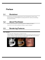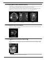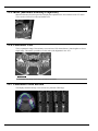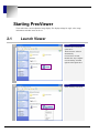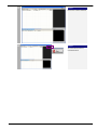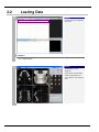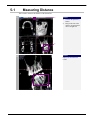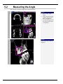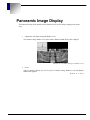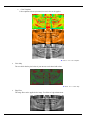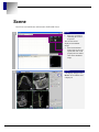
1
Document No.DC-2008-013-05P PrexViewer User’s Manual Rev. 2.2 PreXion, Inc. Index 1. PREFACE 1-1 1-2 1-3 DISCLAIMER ABOUT PREXVIEWER RENDERING FEATURES 4 4 4 1-4 1-5 MINIMUM SYSTEM REQUIREMENT UNSUPPORTED FUNCTIONS 7 7 1.3.1 1.3.2 1.3.3 1.3.4 1.3.5 1.3.6 1.3.7 2. 4 5 5 5 6 6 6 8 2-1 2-2 2-3 LAUNCH VIEWER LOADING DATA DISPLAY ADJUSTMENT 8 10 12 2-4 2-5 3DVR IMAGE ADJUSTMENT MPR IMAGE ADJUSTMENT 15 16 2.5.1 2.5.2 3. Window Level Panning Zoom In/Out Rotation Slice Window level adjustment RaySum Display CUTTING 3-1 3-2 USING AN OUTLINE USING THE SLAB FUNCTION 3.2.1 4. Example Use of the Slab Function CPR FUNCTION 4-1 4-2 CPR MODE SCREEN CREATING CROSS-SECTION IMAGES 4.2.1 5. Swiching Cross-Section Images to RaySum Images MEASUREMENT FUNCTION 5-1 5-2 6. MEASURING DISTANCE MEASURING THE ANGLE PANORAMIC IMAGE DISPLAY 6-1 6-2 6-3 6-4 6-5 6-6 6-7 6-8 2 3DVR MPR (Multi Planar Reconstruction) RaySum (Ray Summation) MIP(Maximum Intensity Projection) MinIP (Minimum Intensity Projection) Panoramic CPR Panorama Cross Section STARTING PREXVIEWER 2.3.1 2.3.2 2.3.3 2.3.4 2.3.5 7. 4 LOAD PANORAMIC IMAGE GAMMA SETTING AND WINDOW LEVEL PRESET COLOR TEMPLATE COLOR MAP EDGE FILTER ZOOM SHORTCUTS FLIP 2D IMAGE DISPLAY 12 13 13 14 14 16 16 17 17 19 20 22 22 23 25 26 27 28 29 32 34 36 38 40 43 44 46 48 7-1 7-2 CHANGING THE LAYOUT ADJUSTMENT OF THE MULTI-SETTING DISPLAY 49 51 8. SCENE 52 9. CONTACT INFORMATION 53 PrexViewer User’s Manual 3 1. Preface 1-1 Disclaimer PrexViewer is a review software application. Please refer to PreXion3D Viewer Software [of the PreXion3D Scanner] for clinical diagnostics. By running the PrexViewer software you acknowledge having read the disclaimer. 1-2 About PrexViewer PrexViewer Data CD(“Data CD”) is generated by PrexViewer CDMaker(“CD Maker”). The PrexViewer can run without installation on Windows computers and laptops. 1-3 Rendering Features 1.3.1 3DVR This is a 3D volume rendering image. It is abbreviated as VR. Volume rendering is a visualization method that uses volume data consisting of cubes called voxels. This is used to visualize the 3D image to the interior, and image is dislplayed by adding colors and shadows that have been calculate using the light penetration and reflection. 4 PrexViewer User’s Manual 1.3.2 MPR (Multi Planar Reconstruction) MPR stands for the Multi Planer Reconstruction method. This method stacks the slices to create solid volume data which can be used to display freely generated cross-section images. Cross sections from different angles can be displayed based on multiple three-dimensionally imaged image data such as horizontal cross sections (Axial) and vertical cross sections (Sagittal). This is used to make a detailed check of the affected area and other applications. <Axial> <Coronal> <Sagittal> 1.3.3 RaySum (Ray Summation) This is the ray summation method. The CT value is added to the projected rays to create an image that mimics a simple X-ray photograph. 1.3.4 MIP(Maximum Intensity Projection) Maximum Intensity Projection provides a display that emphasizes the areas with the highest CT values. This is displayed in a 3D monochrome image. This is used to easily identify the overall shape, implant areas, etc. CAUTION ・ An MIP image differs from a simple X-ray projection image. PrexViewer User’s Manual 5 1.3.5 MinIP (Minimum Intensity Projection) Minimum Intensity Projection provides a display that emphasizes the areas with the lowest CT values. This is used to check nerve holes and similar areas. 1.3.6 Panoramic CPR This is a panoramic image. Discretionary cross sections of 3D volume data are joined together to form a single image. This makes it possible to see the entire tooth alignment in one view. CAUTION ・ This differs from images taken using a panorama X-ray machine. 1.3.7 Panorama Cross Section This displays the discretionary cross sections of a panorama CPR image. 6 PrexViewer User’s Manual 1-4 Minimum System Requirement Operating System: WindowsXP Service Pack2, Windows7 CPU: Intel Pentium4 or later (SSE2 feature must be required) Memory: 512MB Optical drive: CDROM (x52 or faster recommended) Display: 1024x768 pixel 1-5 Unsupported Functions This product does not support following functions. Printing 2D/3D protocol (movie) DICOM file import/export Save Scene Simple Report/Interactive Report Multi Data Mask Implant Planning Fusion PrexViewer User’s Manual 7 2. Starting PrexViewer These methods are used to adjust the image display. The display settings for angle, color, image information, and other items can be set. 2-1 Launch Viewer 1 Operation Insert the Data CD into the optical drive. The PrexViewer will start automatically. If viewer does not start, Double click ‘My Computer’ icon on Desktop, and then right click the optical drive. 2 Operation Select AutoPlay from menu. 8 PrexViewer User’s Manual 3 Operation PrexViewer will be launched 4 Operation To exit from PrexViewer, click Exit button. PrexViewer User’s Manual 9 2-2 Loading Data 1 Operation Double click the examination to be read. Note • The data can be read from the series list. Double click on the series to be read or right click on the series and then click on Open 3D View. 2 Operation The Review screen is displayed. Of the series included in the selected examination, the series with the most images is read. 10 PrexViewer User’s Manual 3 Operation To return to Patient screen, click Patient List button. PrexViewer User’s Manual 11 2-3 Display Adjustment The tool buttons at the top left are used to zoom, rotate, and change the display position of the images. Note ・ Adjustment can also be performed from the menu that is displayed by a right click. 2.3.1 Window Level After clicking on the button, drag on the screen display view image to change the window level. The window level can also be changed without using a button by dragging on the screw display view image with the right and left buttons at the same time. When not using a button Simultaneous right and left drag Left drag 12 PrexViewer User’s Manual 2.3.2 Panning After clicking on the button, drag right or left, up or down on the screen display view image to change the display position. The display position can also be changed without using a button by using the mouse right button to drag right or left, up or down on the screen display view image. When not using a button Right drag Left drag 2.3.3 Zoom In/Out After clicking on the button, drag on the screen display view image to zoom in or zoom out the display. The zoom can also be done without using a button by dragging the wheel button up or down on the screen display view image. When not using a button Wheel drag (vertical) Left drag PrexViewer User’s Manual 13 2.3.4 Rotation This is used with the 3DVR image display. After clicking on the button, drag on the screen display view 3DVR image to rotate the image display. This cannot be used for MPR images. Select this button when changing the screen. Left drag 2.3.5 Slice This is used with MPR image displays. After clicking on the button, drag on the screen display view MPR image to move the slice. Click on the [▼] button to specify the slice movement speed. This cannot be used for 3DVR images. Left drag 14 PrexViewer User’s Manual 2-4 3DVR Image Adjustment The 3D Settings tab is used to adjust the 3DVR image display. <3DVR Example> PrexViewer User’s Manual 15 2-5 MPR Image Adjustment The MPR image display can be adjusted using the MPR operation panel. 2.5.1 Window level adjustment Window level adjustment is set using the Window Level tab of the MPR operation panel. This adjustment can be set by directly inputting the window width value in WW and the window level value in WL. In addition, the slide bar can be dragged to set the window level and both knobs of the slide bar can be dragged to set the window width. Slide bar Knobs 2.5.2 RaySum Display The three basic windows slice thickness can be set using the RaySum tab of the MRP operation panel. Check the box for RaySum and then select Thickness from the list. To move by the selected RaySum mode thickness, remove the check from the box for Snap to Slab. CAUTION • 16 When a check is place in the box for Snap to Slab, the normal MPR image slices are moved one at a time. PrexViewer User’s Manual 3. Cutting Freely cutting any area allows you to remove unnecessary information and display only the area of interest. 3-1 Using an Outline An outline and anchor points are displayed when an MPR is displayed. The outline on the MPR image can be dragged to cut the 3DVR image. Outline An outer frame broken line is displayed on each image. <Flow when cutting away the front portion> Move the outline to the cut position on the MPR (axial) image. 3DVR image before cut MPR (axial) image PrexViewer User’s Manual 3DVR image after cut 17 1 Operation Drag the outline to the area to be cut on the MPR image. 2 Operation The area in front of the drag is cut off and the cut 3DVR image is displayed. 18 PrexViewer User’s Manual 3-2 Using the Slab Function This function can be used to cut at a diagonal to the oblique coordinates or create a cut image that leaves just a specified thickness (slab). An oblique can be created by dragging the cross line and anchor point. Aligning the cut with the tooth alignment makes it possible to create an MIP image of just the required area and a MinIP image that shows an overall image of a neural tube. Cuts at the thickness specified for the cut line Cut line Cuts at the thickness specified for the cut line Cut line Cross line Anchor points Note ・ An oblique is a discretionary cross-section image. A discretionary diagonal image is called a double oblique. <Flow when cutting using the slab function> Move the green line on the MPR (axial) to the place to be cut. Use the yellow lines on both sides of the green line to adjust the thickness. PrexViewer User’s Manual A 3DVR image cut to the specified thickness is displayed. 19 3.2.1 Example Use of the Slab Function 1 Operation Move the center of the cross lines to the area to be shown by the Slab function. The cross lines are moved by dragging them at their center. 2 Operation Click on the Slab tab of the 3D operation panel and place a check in the box for Slab. 20 PrexViewer User’s Manual 3 Operation Move the cross lines and anchor points to adjust the display area. Drag the displayed yellow line to change the thickness of the displayed area. Operation 4 The 3DVR image cut the set slab thickness is displayed. Note ・ Drag the anchor points to change the cut direction. ・ Right click on the 3DVR image to switch between MPR, MIP and MinIP images. PrexViewer User’s Manual 21 4. CPR Function Curved Planar Reconstruction (CPR) is one type of MPR method. With MPR straight line cross sections are displayed, but with CPR free curve cross-section views (cross-section images) are displayed. This function can be used to create discretionary cross-section images. 4-1 CPR Mode Screen Click on the [CPR] button from the tool buttons at the top right of the Review screen to switch to the CPR mode. A free curve can be drawn in the CPR mode and displayed and analyzed as a continuous cross-section view. CPR button 22 PrexViewer User’s Manual 4-2 Creating Cross-Section Images A continuous horizontal cross-section view is called a cross-section image. When a curve is drawn in the CPR mode screen, a cross-section view that intersects with the drawn curve (CPR line) is created. The intersecting lines are called cross-sections and continuous horizontal cross-section views corresponding to the number of displayed cross sections are created. The CPR line cross-section view is displayed as a panoramic image. <Flow when creating a cross-section image> 3DVR Image Draw the cut line (CPR line) Put cross sections in the CPR line) CPR line cross-section view (panorama display) 1 Cross-section views Operation Click on while holding down the Ctrl key at the MPR view and draw a discretionary CPR line. A green line will be drawn. CPR line Note • • To clear the drawn CPR line, click on the [Reset] button from the CPR tool buttons. The lines shown on both sides of the drawn CPR lines show the CPR line slice. PrexViewer User’s Manual 23 2 Operation Drag the anchor points to correct the drawn CPR line. To delete the anchor points, click on while holding down the Shift key. Anchor Points 3 Operation The cross-section images for the drawn CPR line are displayed in the cross-section view. The drawn CPR line panoramic image is displayed in the panorama view. 24 PrexViewer User’s Manual 4.2.1 Swiching Cross-Section Images to RaySum Images Cross-Section images with CPR mode can be swiched to RaySum Images. 1 Operation Display the cross-section image and click button on the top of the screen. 2 Operation 1. Check the box of [RaySum]. 2. Select the thickness from the pull down menu. 3. Click [OK] button, the cross-section image swiched to RaySum image is displayed. (1) (2) (3) PrexViewer User’s Manual 25 5. Measurement Function The discretionary distance on an image, the surface area of an area of interest, signal values, and other values can be measured in the Review screen. The Measurement menu is used for measurements. The Measurement menu is displayed by clicking on the [Measurement] button of the tool buttons at the top left of the Review screen. Button Name Description Select and move measurement result values, lines, etc. Select Delete measurement results, lines, etc. Delete Measure straight lines. Drag to draw a straight line. Displays the length. Distance Multiple Distance Relative Distance Angle 26 Line Measure curve distance. Click on to draw a curve. Double click on the end point to display the measurement results. Measure the relative distance of multiple lines. Drag to draw a straight line. The first line is used as the reference and the distance relative value for the second and subsequent lines is displayed. Measure the angle of two straight lines. Drag to draw a straight line. The first line is used as the reference and the angle with the second is displayed. PrexViewer User’s Manual 5-1 Measuring Distance This is used to measure the distance of the drawn line. 1 (1) Operation 1. 2. Click on the [Distance] button. Drag on the area of the image to be measured to draw a straight line. (2) 2 Operation Display the measurement results. PrexViewer User’s Manual 27 5-2 Measuring the Angle This is used to measure the angle between the drawn lines. 1 (1) Operation 1. 2. 3. Click on the [Angle] button. Drag on the discretionary position on the image to draw a straight line. From the starting point of the first line drag to draw a straight line. (2) (3) 2 Operation The measurement results are displayed. 28 PrexViewer User’s Manual 6. Panoramic Image Display The Panoramic image can be loaded from the Patient List screen.The image is displayed in various ways. Adjustment of Gamma setting and Window Level The Gamma setting, Window Level (WL) and the Window Width (WW) can be changed. ► Refer to 6-2 Gamma Setting and Window Level. Preset Only by clicking a button, one of five presets of Gamma setting, Window Level and Window Width can be applied. ► Refer to 6-3 Preset. PrexViewer User’s Manual 29 Color Templates Color templates such as sepia-toned, inverted color can be applied. ► Refer to 6-4 Color Template. Color Map The area which has the pixel value of your interest can be tinted with colors. ► Refer to 6-5 Color Map. 30 Edge Filter The image filter can be applied to the image. Two filters of edge enhancement. PrexViewer User’s Manual ► Refer to 6-6 Edge Filter. Flip The image can be flipped vertically and/or horizontally. ► Refer to 6-8 Flip. PrexViewer User’s Manual 31 6-1 Load Panoramic Image Load a panoramic image into Panoramic Image View from Patient List. When the scan is done, an panoramic image is generated in Series 100. 1 Operation Click the Study data in the upper list of Patient List screen to display.the Series List at the bottom of the screen. Double click the series that has the number 100. It must have only one image in it. 2 Operation The panoramic image is loaded immediately in the Panoramic Image View. 32 PrexViewer User’s Manual 3 Operation Click on [Enable/Disable Orientation], the orientation display is displayed. PrexViewer User’s Manual 33 6-2 Gamma Setting and Window Level The Gamma setting, the Window Level and the Window Width can be adjusted. 1 Operation Click on the icon for Panorama Histogram floating panel on upper right of the screen. 2 Operation The Panorama Histogram floating panel is displayed. You can change Gamma setting, Window Level and Window Width here. Note that Window Level and Window Width can be changed by mouse operation described in 2-3 Display Adjustment. 34 PrexViewer User’s Manual 3 Operation An example of Gamma setting. Gamma is set to 0.58. 4 Alternative Operation The Window Level and the Window Width can be adjusted in the panel on the right side of the screen, too. PrexViewer User’s Manual 35 6-3 Preset You can apply the preset Gamma setting, window level and the window width to the image. 1 Operation Click one of the buttons in [Preset] section in the panel. (e.g. Click [Tooth2]) 2 Operation The preset Gamma setting, window level and the window width is applied to the image. 36 PrexViewer User’s Manual 3 Operation To change the preset value, right click [Preset] button after adjusting the Gamma, window level and window width. Input the new button name on the Set Panorama Preset window and click [OK] button. [Default] button reverts the values to the factory setting. PrexViewer User’s Manual 37 6-4 Color Template Different types of the color template can be applied. 1 Operation Click one of the buttons in [Color Template] section in the panel. If you choose [Rainbow], the image is switched to the color gradation from blue to red. 2 Operation If you choose [Sepia], the image will be switched to brownish-red. 38 PrexViewer User’s Manual 3 Operation If you choose [Invert], the color of the image will be inverted. PrexViewer User’s Manual 39 6-5 Color Map You can color the area which has the specified pixel value range. 1 Operation Click on [Display pixel value] button. You can start from the 2nd operation below without this step. In that case, the pixel value cannot be checked in the 2nd operation because the pixel value is not displayed. 2 Operation Move the cursor and double click on the pixel which has the pixel value you are interested in. This pixel value will be the center value. CAUTION • 40 In the panoramic image, the CT value is not displayed but the pixel value. PrexViewer User’s Manual 3 Operation The area that has pixel value close to the center value (the center value ± range) is colored. The original image can be observed even if colored, only when you chose the Gray color template. 4 Operation Double click again to add another area of pixel value range. You can have up to three areas. PrexViewer User’s Manual 41 5 Operation You can change the color of the area. Right click the row to show the pull down menu. Select [Color Edit] to change colors. Select [Up] or [Down] to change the lap order. Select [Remove] to remove the colored area. 6 Operation Use the range slider bar to adjust the range of pixel value to color. 7 Operation Click [Remove All] button to remove all the colored areas. 42 PrexViewer User’s Manual 6-6 Edge Filter You can apply the image filter that enhances edges. 1 Operation Click one of the filter buttons in the [Filter] section of the panel to apply the image filter. Note • [No Filter]: The original image • [Sharpen 1]: Edge enhance. When you load an image, this filter is applied. • [Sharpen 2]: Stronger edge enhancement than Sharpen 1. 2 Operation This is an example of [Sharpen 2] PrexViewer User’s Manual 43 6-7 Zoom shortcuts There are two zooming shortcut buttons in the [Zoom] section of the panel. 1 Operation Click [Fit] button to make the image fit the current viewing area. Left is an example result. Click [100%] button to make the image pixel-by-pixel magnification. Pixel-by-pixel means that 1 pixel of image corresponds to 1 pixel of LCD display. Note • The display magnification ratio will be changed when you perform another zooming operation. • The display magnification ratio is changed when you show or hide the operation panel on the right side of the screen. 2 Operation Left is an example result of [100%] zoom. 44 PrexViewer User’s Manual 3 Alternative Operation Right click on the screen, the menu is displayed. The same operation as using [Zoom] button can be done from the menu. PrexViewer User’s Manual 45 6-8 Flip The image can be flipped horizontally and/or vertically. Please note that the image is displayed the other way round in right and left. Enable the orientation display and indicate LR code to avoid misidentifying. 1 Operation Click [VFlip] button to flip the image vertically. The button is highlighted to indicate the image is flipped. 2 Operation Click on [HFlip] button to flip the image horizontally. 3 Operation This is an example of horizontally flipped image. Make sure to enable the orientation display. ► Refer to 6-1 Load Panoramic Image for display. 46 PrexViewer User’s Manual the orientation 4 Operation Click [Reset] button to revert to the original status. PrexViewer User’s Manual 47 7. 2D Image Display Multiple 2D images can be displayed at the same time just like for film diagnosis. Multiple displays of one slice or simultaneous display of multiple slices are possible. The types of slice multiple displays are explained below. Multi-setting Display This shows multiple displays of one slice. Each display is shown at a different angle, so several angles can be checked at one time. This is shown by clicking on the [Multi-setting] button on the left side. Multi-setting Multi-setting display view 2D operation panel Multi-slice display This displays multiple slices at one time. This allows the differences of each cross section to be checked. This is shown by clicking on the [Multi-slice] button on the right side. Multi-slice Multi-slice display view 48 2D operation panel PrexViewer User’s Manual 7-1 Changing the Layout The multi-setting display layout can be changed from 1×1 to 2×2, and the multi-slice layout can be changed from 1×1 up to 5×5. This section explains the method for changing the multi-slice display layout. 1 Operation Click on the [Multi-slice] button. Note • For the Multi-setting display, click on the left side [Multi-setting] button. 2 Operation Click on the [Change Layout] button and drag the number to be displayed to change to the number of images you want to display. PrexViewer User’s Manual 49 CAUTION • The [Change Layout] button when the multi-setting display is used differs from that for the multi-slice display. The number of displays that can be specified is 1×1 or 2×2. 3 Operation The specified layout is displayed. 50 PrexViewer User’s Manual 7-2 Adjustment of the Multi-setting Display The top left tool buttons and 2D operation panel can be used to adjust the 2D image display. Note ・ The top left tool buttons are used in the same manner as when working with 3D images. ■ Window Level Adjustment This is used to adjust the displayed slice image window width and window level. This can be set for each displayed slice. The setting method is the same as for 3D display. The slices are set in the order of top left, top right, bottom left, bottom right from the top of the 2D operation panel. (1) (2) (1) (2) (3) (4) (3) (4) PrexViewer User’s Manual 51 8. Scene PrexViewer can load Scenes which saved in PreXion3D Viewer. 1 (1) Operation 4. Select the examination containing the scene to be opened. The saved scenes are displayed as thumbnail images. 5. Select the thumbnail (2) image of the scene to be opened and click on the [Open] button or double click on the thumbnail image. 2 Operation The display changes to the Review screen and the scene is displayed. 52 PrexViewer User’s Manual 9. Contact Information PreXion, Inc. Address: Tel: Fax: E-mail: 411 Borel Avenue, Suite 550 San Mateo, CA 94402, USA +1-650-212-0300 +1-650-212-0310 [email protected] Customer Service Tel: +1-650-212-0314 E-mail: [email protected] PrexViewer User’s Manual 53