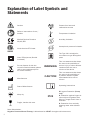
1
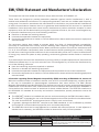
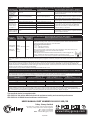
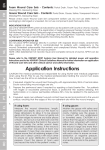
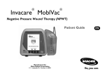
User Guidelines for the
VENTURI® MiNO Negative Pressure
Wound Therapy System
Explanation of Label Symbols and
Statements
Protect from heat and
radioactive sources
Caution
Refer to instructions of use /
booklet
Temperature limitation
Medical Devices Directive
93/42/EEC
Humidity limitation
Atmospheric pressure limitation
North America ETL listed
The Type 19 is suitable for
connection to type BF applied
parts
Class II Equipment (Double
Insulated)
Do not dispose of with the
normal household waste (please
refer to www.talleygroup.com
for further details)
Manufacturer
WARNING
This is a statement that alerts
the user to the possibility of
serious injury or other adverse
reactions with the use or
misuse of the device
CAUTION
This is a statement that alerts
the user to the possibility of
a problem with the system
associated with its use or
misuse
Operating Instructions
Date of Manufacture
Keep dry
Fragile, handle with care
IP22
IP: Ingress Protection (Pump
only)
2: Protection against fingers or
other object not greater than
80mm in length and 12mm in
diameter
2: Protection from vertically
dripping water when tilted to
15o)
Note: Abbreviation:
Negative Pressure Wound Therapy is abbreviated to ‘NPWT’ throughout this document
1
Contents
Explanation of Symbols and Statements
Introduction / Intended Use
Page
1
2
Contraindications3
List of Components
3
Cautions and Warnings Information
3
How to Apply NPWT
5
User Information
6
Battery Information
6
Care and Maintenance
7
Warning and Fault Indicators
8
Specification9
EMI / EMC Statement
EMC Manufacturer’s Declaration
10
Back Cover
Introduction / Intended Use
Thank you for choosing to use the VENTURI® MiNO Negative Pressure Wound Therapy
(NPWT) system from Talley. In doing so you have selected an efficient, competitively
priced product for the treatment of many wounds including pressure ulcers, dehisced
surgical wounds, diabetic/neuropathic ulcers, venous leg ulcers, post surgical wounds,
sinus drainage and management, traumatic wounds and pre- and post-op flaps/grafts.
The VENTURI® MiNO NPWT system features a lightweight, versatile vacuum power unit
which benefits from dual-power technology, offering a seamless choice of mains or
battery operation. The integral battery is charge-optimised, and provides long-lasting
power back-up when needed. The battery operation option allows the system to function
away from a mains power supply for extended periods of time, allowing the patient full
mobility during therapy, if required (a carry case with shoulder/waist strap is supplied).
NPWT is applied utilising a choice of VENTURI® MiNO Weekly Therapy Wound Care Sets
which include a choice of gauze or foam dressing, a drainage canister, silicone drains and
transparent adhesive film.
The VENTURI® MiNO NPWT system will benefit from careful installation and use,
providing a long and effective service life. Please read and understand this document
completely before applying NPWT.
2
CONTRAINDICATIONS
Do not place NPWT dressings directly in contact with exposed blood vessels, anastomotic
sites, organs or nerves.
NPWT is contraindicated for patients with:
1. Malignancy in the wound
2. Untreated osteomyelitis
3. Non-enteric and unexplored fistulas
4. Wounds with difficult haemostasis
5. Necrotic tissue with eschar present
NOTE: After debridement of necrotic tissue and complete removal of eschar, NPWT can be
used.
List of Components
Your VENTURI® MiNO NPWT system should comprise the following items - please ensure you
have all of these before installation.
Note: Wound Care Sets are supplied separately.
l VENTURI® MiNO (TG600/14)
l 5V Mains adapter FW7662M/05
l Carry bag*
* may not be included in all markets
WOUND CARE SETS (supplied separately)
l Gauze Weekly Therapy Wound Care Set
l Foam Weekly Therapy Wound Care Set
l Slim Foam Weekly Therapy Wound Care Set
ALSO AVAILABLE
l 5V Mains adapter FW7662M/05
l Carry bag
Cautions and Warnings
lThere are no special skills required to operate the pump unit however,
Negative Pressure Wound Therapy should only be used under the advice,
recommendation and supervision of a licensed Physician and / or a registered nurse.
lThe medical professional is responsible for applying his/her best medical judgment
when using this system. Prior to use, the medical professional(s) treating the wound
must assess how to best use the system for an individual wound.
lSelect correct setting for therapy required. Care should be taken not to accidently change
pressures once set as the efficiency of the therapy may be reduced. This could also be
caused by pets, pests or children.
3
Cautions and Warnings (continued)
lThe electricity supply is of the type indicated on the power adapter.
lCheck the power adapter lead is free from damage and is positioned so as not to cause
an obstruction, or injury, e.g. strangulation. Do not position the vacuum power unit or
power adapter such that makes it difficult to disconnect the supply or drain plug.
lEnsure the power adapter lead, drain tube or vacuum power unit cannot become trapped
or crushed, e.g. via raising or lowering of bed or bed rails or any other moving object. All
tubes must be free of kinks, twists, properly connected and positioned so as not to cause
an obstruction or injury.
lDo not place the vacuum power unit or power adapter on or near a heat source.
lNever use the power adapter whilst placed on top of or near to material which is
flammable or can be damaged by heat. (The supplied power adapters plug directly into
the power source partly mitigating this issue).
lThe vacuum power unit must only be used with the approved power adapter supplied by
Talley (see Specification on page 9)
lThe VENTURI® NPWT system (Vacuum power unit and power adapter) is not used in the
presence of flammable anesthetics or in an oxygen enriched environment.
lSuitable for continuous use.
lNot suitable for sterilisation.
lThe materials used in the manufacture of all components of the system comply with the
required fire safety regulations.
lTalley advice against smoking whilst the system is in use, to prevent the accidental
secondary ignition of associated items which may be flammable.
lDo not modify any of the medical devices or accessories in any way or use unspecified
parts. Do not use unspecified parts.
lChoking may result from a child swallowing a small part that has become detached from
the ME equipment.
lA Weekly Therapy Wound Care Set must be used with the VENTURI® MiNO system to
carry out NPWT.
lPlease refer to the ‘Instructions for Use’ leaflet supplied with Weekly Therapy Wound
Care Set for dressing application and setup. Note that the dressings in the set are sterile
and for single patient / single use only, not intended for reuse.
lIntended for home healthcare and professional healthcare facility environments.
lThe device is intended to be used with its carry bag.
lDo not connect to any other medical device or equipment.
lThe power unit and power adapter should be cleaned between patient use (refer to Care
and Maintenance Section).
lThe VENTURI® MiNO vacuum power unit is non-serviceable.
lWireless equipment such as mobile phones should be kept at least 10 feet or 3.3m away
from this equipment.
lThe above warnings, cautions and any safety considerations should be observed on a
routine and regular basis, not only upon installation.
4
How to Apply NPWT
NB. A Weekly Therapy Wound Care Set must be used with the VENTURI® MiNO system to carry
out NPWT (see page 3 for available options). Please refer to the ‘Instructions for Use’ leaflet
supplied with Weekly Therapy Wound Care Set for dressing application and setup.
CAUTION! The medical professional is responsible for using his/her best medical judgment
when using this system. Prior to use, the medical professional(s) treating the wound must
assess how to best use the system for an individual wound.
1. Remove all packaging from the power unit and mains adapter.
Note: If the battery charge appears to be partially depleted on first use, the power unit
should be used with the power adapter, to fully charge the battery during operation.
2.Attach the drainage canister to the VENTURI®
MiNO power unit by lining up the two parts,
pushing together and twisting to lock (Fig. 1).
Ensure canister is correctly located and secured
otherwise NO CANISTER alert will appear and
power unit will not operate.
Fig. 1
3. Prepare and seal wound as described in the
Weekly Therapy Wound Care Set ‘Instructions for
Use’.
4. Attach the portal drain to the power unit canister by pushing the tubing firmly and fully
onto the tubing connector located on the top of the canister. Push the tubing down into
the channel to assist with the routing of the tubing.
5. OPERATING
THE VACUUM POWER UNIT:
a)If using the mains power adapter, insert the smaller end (DC outlet) of the supplied
power adapter cable into the side of the VENTURI® MiNO power unit, and the other
end into the appropriate power outlet. The power adapter indicator should be
illuminated.
NB. The battery will charge when the unit is connected to the power source
(indicated by the battery charge icon on the top right of the display screen) and
provides automatic power back-up if the external power supply or adapter fails. It
is recommended to use the power adapter when convenient to do so as this will
ensure the battery is fully charged when needed. A fully discharged battery will take
a number of hours to fully charge.
b) Press RUN/STOP button (Fig. 2) to initialise and run the power unit
(operating pressure and battery charge status will be displayed).
c)
The default operating vacuum is 80mmHg. The vacuum level can be
adjusted between a choice of 80mmHg or 120mmHg by pressing
Fig. 2
the UP/DOWN arrow button (Fig. 3).
NB. The display screen is only illuminated for a short period after
button operation in battery mode. Press the RUN/STOP button
briefly to illuminate the screen.
6. Once the power unit is running, observe the wound site. The dressing
Fig. 3
should contract noticeably, becoming firm to the touch. If the dressing
fails to contract, the dressing has not been completely sealed.
Reinforce the dressing seal and/or adjust the drain and initiate suction again.
5
How to Apply NPWT (continued)
NB. During system set-up, various checks and internal tests take place and if any
intervention is required an alert will occur, but not until several minutes after set-up.
WARNING: Particularly when used outside of a medical institution, get immediate
medical assistance from those responsible for the prescription and setting of
the NPWT system should any of the following occur:- obvious bleeding or pain;
the wound site or exudate presents unexpected changes in its condition, colour or odour;
the wound dressing becomes detached or ineffective; the tubing becomes blocked.
7.To change or remove dressing, switch off power unit (press and hold the RUN/
STOP button until power unit beeps). Clamp the drain tubing and remove by
lifting the tubing up from the routing channel and pulling from the tubing
connector on the canister. Dispose of used Wound Care Set according to local
clinical waste policy. If required, apply new Wound Care Set and continue NPWT.
8.Canisters should be replaced as required or weekly. To change canister,
clamp and remove Wound Care Set tubing as above (this can be reconnected
to new canister and unclamped if wound dressing is not being changed).
Rotate canister to unlock and remove from power unit. Dispose of used
canister according to local clinical waste policy. If continuing NPWT, attach
new canister and connect Wound Care Set tubing as previously described.
9. To switch off the power unit, press and hold the RUN/STOP button until power unit
beeps.
10. Place the user manual in a safe place for future use.
User Information
Fig. 4
lThe VENTURI® MiNO is supplied with a carry bag which
can be worn on the shoulder, across the body or around
the waist. When placing the power unit in the carry
bag, make sure that it is oriented so that the tubing exits
the top of the bag without kinking, bending or straining
against the connector port to ensure correct operation.
(Fig. 4).
lTo ensure correct operation, the VENTURI® MiNO power unit should always be kept in an
upright position. The power unit will display and sound an alert if the unit is over tilted
(refer to Warning and Fault Indicators on page 8).
Battery Information
lA fully charged battery should operate the power unit continuously for at least 24 hours.
lCharge status is shown on the display of the power unit when it is in operation.
lThe power adaptor will display a green light when delivering a charge to the VENTURI®
MiNO power unit.
lThe battery is not serviceable and cannot be removed, changed or replaced.
l Use only the mains adapter supplied with the system.
6
Battery Information (continued)
CHARGING THE BATTERY
The battery will charge when the unit is connected to the power source,
indicated by the battery charge icon on the top right of the display screen, (Fig.
5) (only displayed when the power unit is switched on) and provides automatic
power back-up if the external power supply fails. It is recommended to use
the power adapter when convenient to do so as this will ensure the battery is
fully charged when needed. A daily charge is recommended. A fully discharged
battery will take a number of hours to fully charge and can be left to charge
overnight. NB. A full charge is indicated by the ‘lightening bolt’ symbol only.
80
-mmHg
Fig. 5
Care and Maintenance
POWER UNIT
Always disconnect the VENTURI® MiNO power unit from the power adapter and the power
adapter from the power source before carrying out cleaning. Check all electrical connections
and power lead for signs of excessive wear. The power unit / power adapter can be wiped
down with detergent or disinfectant solution or wipe*. Do not use solvents. Unsuitable
for sterilisation. Dispose of the power unit / power adapter in accordance with the local
regulations including WEEE requirements. The power unit / power adapter should be
cleaned between patient use as a minimum.
SERVICING The VENTURI® MiNO power unit is non-serviceable. Should a fault occur, please
refer to the ‘Warning and Fault Indicators’ section on page 8. If the power unit fails to operate
correctly please contact Talley.
* In line with the MHRA Medical Device Alert (MDA/2013/019), Talley advises customers
to use pH neutral, high level disinfectant cleaning products to sanitise reusable medical
devices to prevent damage to materials and the degradation of plastic surfaces after
prolonged use. The use of inappropriate cleaning and detergent materials on medical
equipment could damage surfaces and may compromise the ability to decontaminate
medical devices adequately or may interfere with device function. Talley recommends the
use of TECcare® CONTROL antimicrobial wipes and fluid to clean and decontaminate all
products it supplies to health and social care facilities. TECcare® CONTROL products provide
class leading broad spectrum, high level disinfection with an exceptional safety profile. Being
pH neutral TECcare® CONTROL can be universally used on all hard and soft surfaces without
any detrimental effect. TECcare® CONTROL is CE marked for cleaning medical equipment.
WEEKLY THERAPY WOUND CARE SETS
Wound Care Sets and canisters are disposable and intended for single use only. After
use please dispose of in an appropriate manner in accordance with local regulations and
hospital best practice.
TRANSPORT AND STORAGE
7
Handle with care. Please report instances of damage or impact to Talley Service Department.
Transport
–25 °C without relative humidity control; and
+70 °C at a relative humidity up to 93 %, non-condensing.
An atmospheric pressure range of 700 hPa to 1 060 hPa.
Suitable for all standard modes of transport when in the correct packaging.
Care and Maintenance (continued)
OPERATIONAL CONDITIONS
A temperature range of +5 °C to +40 °C;
A relative humidity range of 15% to 93%, non-condensing
Operational Atmospheric Pressure: 700 hPa to 1060 hPa
Suitable for pollution degree 2
Operational altitude ≤ 2 000 m
IP Rating: IP22 pump only
MANUFACTURER’S GUARANTEE
The VENTURI® MiNO power unit is covered by a 12 month manufacturer’s guarantee. The
intended design life is 2 years.
Warning and Fault Indicators
!
Fig. 6
The VENTURI® MiNO power unit features audible and graphic indicators to alert
when user intervention is required. Once corrective action has been taken the
alert will self-cancel and normal operation will resume. The display screen will
toggle between the alert graphic and the instruction to refer to the user manual
for more information (Fig. 6). The illuminated display and sounder will persist
whilst the alert state is active. Should an alert persist or immediately re-occur,
contact Talley. All sounders can be silenced and messages cleared by pressing
and holding the RUN/STOP button to switch the power unit off, whilst corrective
action is taking place.
WARNING INDICATORS
NO CANISTER (Fig. 7) – indicates canister is missing or is not
correctly fitted. The power unit will fail to operate whilst this message
is displayed. Check that canister is correctly located and secured, as
detailed on page 5.
!
CANISTER FULL (Fig. 8) – indicates that the canister is full and
should be removed/replaced, as detailed on page 6. The
power unit will cease to run until corrective action has been
taken.
CONSTRICTED TUBE/LOW FLOW* (Fig. 9) – indicates
!
tube blockage/constriction or state of low flow. Check that
low flow is not caused by pinched or bent tubing. If exudate
is pooling in the wound bed, the dressing should be changed.
This alert will self-cancel after 5 minutes and will re-occur if
the condition persists. NB. This alert may arise under normal
operation if the wound exudate levels are very low.
CHECK DRESSING* (Fig. 10) / DISCONNECTED TUBE* (Fig. 11)
– indicates vacuum pressure has fallen below minimum allowable
levels, due to either a leak in the dressing or a tube disconnection.
The power unit will continue to run whilst this message is displayed.
Check that wound dressing is completely sealed and that all tubing
connections are secure.
!
Fig. 7
!
!
Fig. 8
!
!
Fig. 9
8
Warning and Fault Indicators (continued)
TILT (Fig. 12) – activates when the power unit is placed
at an angle that could affect the canister full indication.
The power unit will continue to run whilst this message is
displayed. Return the power unit to an upright position.
!
!
Fig. 12
LOW BATTERY (Fig. 13) (only
!
?
appears during battery operation)
Fig. 10
– battery icon at the top left of the
normal operation display screen
flashes on/off, indicating battery charge is
low and battery needs recharging. Plug into
a power source to charge.
FATAL ERROR (Fig. 14) – the screen
displays a letter E followed by a number, indicating an irrepairable
fault. This screen should never appear during normal operation
but if it does, please contact Talley.
+
!
!
Fig. 11
80
!
E1
-mmHg
Fig. 13
Fig. 14
* the sounder can be silenced temporarily by briefly pressing the UP/DOWN button.
Specification
POWER UNIT
Model Ref:
Construction:
Dimensions:
Weight:
DC Input Voltage:
Vacuum Application:
Vacuum Range:
Fixed Internal Battery:
Part Number:
150ml CANISTER
Construction:
Dimensions:
POWER ADAPTER
Mains Adapter Type:
Input:
Output:
Cable Length:
Part Number:
VENTURI® MINO
Venturi v.II TG600/14
Flame retardant ABS
W105mm x D52mm x H112mm
250g
5V Nominal
Continuous
80mmHg or 120mmHg (+/- 5mmHg)
3.7V 11.3mAh Lithium Ion - Polymer - Rechargeable Cell
CE0120:99-90-22-500
ETL:99-90-22-505
INMETRO:99-90-22-504
Textured ABS (includes absorbant media)
W54mm x D52mm x H112mm
FW7662M/05 (supplied)
100-240V ~ / 50-60Hz / 700mA
5V DC / 1.1A
3 metres
34-26-05-105
The above mains adapters are considered part of the ME equipment. The VENTURI® MiNO power unit
must only be used with the specific external power adapter as supplied by Talley.
9
Talley products are manufactured to comply with International and National safety standards.
Talley design and manufacture products to conform to the requirements of ISO9001,
ISO13485 and Directive (93/42/EEC). Talley reserves the right to modify the specification of
any product without prior notice in line with a policy of continual product development. Our
standard terms and conditions apply.
EMI/EMC Statement and Manufacturer’s Declaration
This equipment has been tested and found to comply with the limits of EN 60601-1-2.
These limits are designed to provide reasonable protection against harmful interference in both a
medical and residential environment. This equipment generates, uses and can radiate radio frequency
energy and, if not used in accordance with manufacturer’s instructions, may cause harmful interference
to radio communications. However, there is no guarantee that interference will not occur in a particular
installation. If this equipment does cause harmful interference to radio or television reception or other
equipment, which can be determined by turning the equipment off and on, the user is encouraged to try
to correct the interference by one of the following measures:
l Reorient or relocate the receiving antenna.
l Increase the separation between the equipment.
l Connect the equipment to an outlet on a circuit different from that to which the receiver or equipment
was connected.
The equipment having been tested to operate within the limits of electromagnetic compatibility.
(Immunity to interference from nearby sources radiating radio frequency energy). Sources exceeding
these limits may give rise to operation faults. Where possible the system will sense the interference and
if it is of short duration transparently take countermeasures whilst operating near normally, or failing
this will issue a warning and take measures for the continued safely of the user. Further increased levels
of energy may cause the system to stop operating, continuously generate random faults or continuous
resets.
Try to ascertain the source of the interference by turning nearby or suspect equipment off, and see if the
interference effects stop. In any such event the user is encouraged to try to correct the interference by
one of the following measures:
l Have the interfering equipment repaired or replaced.
l Reorient or relocate the interfering equipment.
l Increase the separation between the equipment and the possible source of the interference.
l Connect the equipment to an outlet on a circuit different from that to which the interfering equipment
was connected.
Information regarding Electro Magnetic Compatibility (EMC) according to IEC60601-1-2, clause 6.8
With the increased number of electronic devices such as PC’s and mobile telephones, medical devices
in use may be susceptible to electromagnetic interference from other devices. The EMC (Electro
Magnetic Compatibility) standard IEC60601-1-2 defines the levels of immunity to these electromagnetic
interferences. From the other hand, medical devices must not interfere with other devices. IEC60601-12 also defines the maximum levels of emissions for these medical devices. The VENTURI® conforms to
this IEC60601-1-2 standard for immunity and emission. Nevertheless, special precautions need to be
observed:
l
l
l
l
The VENTURI® needs to be installed and put into service according to the EMC information below.
The VENTURI® is intended for use in the electromagnetic environment specified in the tables below.
The user of the VENTURI® should assure that it is used in such environment.
In general, although the VENTURI® complies to the EMC standards, it can be affected by portable
and mobile RF communications equipment (such as mobile telephones).
The VENTURI® should not be used adjacent to or stacked with other equipment. In case adjacent or
stacked use is necessary, the VENTURI® should be observed to verify normal operation.
Guidance and Manufacturer’s Declaration: Electromagnetic Emissions (IEC 60601-1-2)
Emissions Test
Compliance
Electromagnetic environment - guidance
RF emissions CISPR 11
Class B
Harmonics emissions 61000-3-2
Class A
Voltage fluctuations / flicker emissions 61000-3-3
Complies
The VENTURI® systems are suitable for use in all establishments,
including domestic establishments and those directly connected to
the public low-voltage pump supply network that supplies buildings
used for domestic purposes.
10
Guidance and Manufacturer’s Declaration: Electromagnetic Immunity (IEC 60601-1-2)
Immunity Test
IEC 60601 Test Level
Compliance Level
Electromagnetic Environment - Guidance
Electrostatic
discharge (ESD)
IEC 61000-4-2
± 6kV contact
± 8kV air
± 6kV contact
± 8kV air
Floors should be wood, concrete or ceramic tile. If floors
are covered with synthetic material, the relative humidity
should be at least 30%.
Electrical fast
transient/burst IEC
61000-4-4
± 2 kV For mains supply lines
± 1kV For input/output lines
± 2 kV For mains supply lines
± 1kV For input/output lines
Mains supply quality for the mains adapter should be
that of a typical commercial and/or hospital environment.
Surge
IEC61000-4-5
± 1kV line(s) to line
± 1kV line(s) to line
Mains supply quality for the mains adapter should be
that of a typical commercial and/or hospital environment.
Voltage dips, short
interruptions and
voltage variations
on mains supply
IEC 61000-4-11
<5%Ur (>95%Ur) for 0.5 cycle
<5%Ur (>95%Ur) for 0.5 cycle
40%Ur (60% dip in Ur) for 5 cycles
40%Ur (60% dip in Ur) for 5 cycles
Mains supply quality for the mains adapter should be
that of a typical commercial and/or hospital environment.
In the event of a mains interruption the VENTURI®
70%Ur (30% dip in Ur) for 25 cycles 70%Ur (30% dip in Ur) for 25 cycles system will automatically use internal battery power,
unless
the battery is exhausted.
>5%Ur (>95% dip in Ur) for 5 secs
>5%Ur (>95% dip in Ur) for 5 secs
Mains frequency
(50/60Hz) magnetic
field IEC61000-4-8
Mains frequency magnetic fields should be at levels
characteristic of a typical location in a typical commercial
and/or hospital environment.
Note: Ur is the A.C. mains voltage prior to application of the test level.
3 A/m
3 A/m
Guidance and Manufacturer’s Declaration: Electromagnetic Immunity (IEC 60601-1-2)
Immunity
Test
IEC 60601
Test Level
Compliance
Level
3 V rms
Conducted RF
150 kHz ~ 80 MHz
IEC 61000-4-6
3 V rms
3 V/m
Radiated RF
80 MHz ~
IEC 61000-4-3
2.5 GHz
3 V/m
Electromagnetic Environment - Guidance
Portable and mobile RF communications equipment should be used no closer to any part of the
VENTURI® including cables, than the recommended separation distance calculated from the
equation appropriate to the frequency of the transmitter.
Recommend separation distance
d = 1.2 √P
d = 1.2 √P 80 MHz to 800 MHz
d = 2.3 √P 800 MHz to 2.5 GHz
where P is the maximum output power rating of the transmitter in watts (W) according to the
transmitter manufacturer and d is the recommended separation
distance in meters (m).
Field strengths from fixed RF transmitters as determined by an electromagnetic site
survey,a should be less than the compliance level in each frequency range.b
Interference may occur in the vicinity of equipment marked with the following symbol:
Note1: At 80 MHz and 800 MHz, the higher frequency range applies.
Note2: These guidelines may not apply in all situations. Electromagnetic propagation is affected by absorption and reflection from structures, objects, and
people.
Field strengths from fixed transmitters, such as base stations for radio (cellular/ cordless) telephones and land mobile radio, AM and FM radio broadcast,
and TV broadcast cannot be predicted theoretically with accuracy. To assess the electromagnetic environment due to fixed RF transmitters, an electromagnetic site survey should be considered. If the measured field strength in the location in which the VENTURI® is used exceeds the applicable RF
compliance level above, the VENTURI® should be observed to verify normal operation. If abnormal performance is observed, additional measures may be
necessary, such as reorienting or relocating the VENTURI®.
b
Over the frequency range 150 kHz to 80MHz, field strengths should be less than 3 V/m.
a
Recommended Separation Distance Between Portable and Mobile RF Communications Equipment and the VENTURI®
The VENTURI® is intended for use in an electromagnetic environment in which radiated RF disturbances are controlled. The user of the VENTURI® can
help prevent electromagnetic interference by maintaining a minimum distance between portable and mobile RF communications equipment (transmitters)
and the VENTURI®® as recommended below, according to the maximum output power of the communications equipment.
Separation distance according to frequency of transmitter in Meters (m)
150 kHz to 80 MHz d = 1.2 √P
80 MHz to 800 MHz d = 1.2 √P
800 MHz to 2.5GHz d = 2.3 √P
0.01
0.01
0.01
0.01
0.12
0.12
0.12
0.12
0.12
0.12
0.12
0.12
0.23
0.23
0.23
0.23
0.1
0.1
0.1
0.1
For transmitters rated at a maximum output power not listed above, the recommended separation distance d in Meters (m) can be estimated using the
equation applicable to the frequency of the transmitter, where P is the maximum output power rating of the transmitter in Watts (W) according to the
transmitter manufacturer. Note: At 80MHz and 800MHz, the separation distance for the higher frequency range applies. Note: These guidelines may not
apply in all situations. Electromagnetic propagation is affected by absorption and reflection from structures, objects, and people.
Output Power of Transmitter in
Watts (W)
This medical device is compliant with:
IEC 60601.1 3rd edition Medical electrical equipment safety and essential performance
IEC 60601.1.11 2010 Home healthcare environment
USER MANUAL PART NUMBER 50-02-15-112/5D
Talley Group Limited
Premier Way, Abbey Park Industrial Estate
Romsey, Hampshire, SO51 9DQ England
TEL: +44(0)1794 503500
FAX: +44(0)1794 503555
EMAIL: [email protected]
01/2015
www.talleygroup.com