1
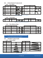
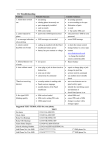
User Manual
Manual Chain Frame Scanner
Safety Warnings / Precautions
KEEP THIS MANUAL – DO NOT LOSE
THIS MANUAL IS PART OF THE ROTIX AND MUST BE RETAINED FOR THE LIFE OF
THE PRODUCT. PASS ON TO SUBSEQUENT OWNERS.
Ensure any amendments are incorporated with this document.
DANGER! The ROTIX is designed for a specific use. Using the
ROTIX outside of its intended use could cause damage to the product.
Read and understand this manual before using.
WARNING! MAGNETIC MATERIAL. The wheels of this device
produce a magnetic field which may cause failure or permanent damage to
items such as watches, memory devices, CRT monitors, medical devices or
other electronics.
People with pacemakers or ICD’s must stay at least 25 cm (10”) away at all
times.
WARNING! Do NOT operate scanner in an explosive environment.
Do NOT operate scanner in the presence of volatile substances.
The WEEE symbol indicates that the product must not be disposed of as
unsorted municipal waste, but should be collected separately.
DISTRIBUTOR:
MANUFACTURER:
Jireh Industries Ltd.
53158 Range Road 224
Ardrossan, Alberta, Canada
T8E 2K4
Phone: (780) 922-4534
Fax:
(780) 922-5766
www.jireh-industries.com
PAGE i of iv
CE0120 Rev 02.01
Table of Contents
1.Introduction 1.1.
1
Product information 1.1.1. 1.1.2. 1.1.3. 1.1.4. Intended use Performance specifications Operating environment Environmental Sealing
1.2. Definition of symbols 1.3.Hardware 1.4.
1.5.
1.3.1. Included tools 1.3.2. Optional tools 1.3.3. Maintenance Two Probe Chain Configuration Setup Chart
Four Probe Chain Configuration Setup Chart 2. Configurations 2.1.
2.2.
2.3.
5
Two Probe Scanning Four Probe Scanning Four Probe Cantilever Scanning 3. Operation 3.1.
1
1
1
1
1
1
2
2
2
2
3
4
5
5
6
7
Setup of Rotix on a Scanning Surface 4. System Components 7
11
4.1.
4.2.
Overhead Adjustable Link Crossover Wheel Block 4.3.
4.4.
4.5.
4.6.
4.7.
Double Chain Mount Trailing Encoder Frame Bar Pivot Buttons Chain Components 4.8.
4.9.
Ratchet Lever Slip Joint Probe Holder 4.2.1. Wheel Removal/Installation 4.7.1. Chain Connection 4.9.1. Probe Holder Setup 4.9.2. Probe Holder Adjustment 4.9.3. Probe Holder Force Adjustment PAGE ii of iv
11
11
12
12
13
13
13
14
15
15
16
16
18
18
4.9.4. Slip Joint Probe Holder Left/Right Conversion 4.10. Cable Management System 4.10.1. Zipper Tube Dovetail Mount 4.10.2. Zipper Tube Setup 4.10.3. Clamp Setup 4.11. Reduced Width Scanning Kit 4.12. Vertical Probe Holder 4.12.1. 4.12.2. 4.12.3. 4.12.4. 4.12.5. Probe Holder Setup
Probe Holder Vertical Adjustment Probe Holder Transverse Adjustment Probe Holder Longitudinal Adjustment Probe Holder Left/Right Conversion 4.13. Magnetic Wheel Kit 4.14. Pre-amp Bracket 20
22
22
23
24
24
25
25
26
27
28
29
31
32
5. Troubleshooting 33
6. Spare Parts 34
6.1.
Kit Components 6.1.1. Encoder Connector Style 6.2.Accessories
6.2.1. 6.2.2. 6.2.3. 6.2.4. Zipper Tube Pre-Amp Bracket Magnetic Wheel Kit Reduced Width Scanning Kit 6.3.
Probe Holders 6.4.
Probe Holder Components 6.5.
Variable Components 6.3.1. Slip Joint Probe Holder Parts 6.3.2. Vertical Probe Holder Parts 6.4.1. Arm Style 6.4.2. Yoke Style 6.4.3. Pivot Button Style 6.5.1. Frame Bars 7. Limited Warranty 34
35
35
35
35
36
36
37
37
38
39
39
39
39
39
39
40
PAGE iii of iv
CE0120 Rev 02.01
PAGE iv of iv
1. Introduction
1.1.
Product information
1.1.1. Intended use
The ROTIX chain scanner is a manually operated scanner which provides encoded
probe positions of two or four probes. The double wheel chain components straddle
the weld and fasten a scanning frame circumferentially around pipe or tubing.
1.1.2. Performance specifications
Minimum
Maximum
Pipe/Tube range
38.1 mm (1.5 in)
965.2 mm (38.0 in)
Umbilical length (Standard kit)
5 m (16.4 in)
X-Axis encoder resolution
9.05 counts/mm (230.0 counts/inch)
1.1.3. Operating environment
The ROTIX chain scanner is designed for use in an industrial environment that is
between -20° C (-4° F) and 50° C (122° F).
1.1.4. Environmental Sealing
Dust tight, water tight (not submersible).
1.2.
Definition of symbols
Instructions to ‘look here’ or to ‘see this part’.
Denotes movement. Instructing user to carry out
action in a specified direction.
Indicates alignment axis.
Alerts user that view has changed to a reverse angle.
PAGE 1 of 41
CE0120 Rev 02.01
1.3.
Hardware
1.3.1. Included tools
Fig. 1 - 3 mm hex driver
Fig. 2 - 3/8 in wrench
The 3 mm hex driver (Fig. 1) is sufficient for all typical operations and adjustments
of the ROTIX. The 3/8 in wrench (Fig. 2) is used to remove and install buttons on
the probe holders.
1.3.2. Optional tools
Some specialized adjustments require tools that are not included with this kit.
Fig. 3 - 1.5 mm
hex wrench
Fig. 4 - 2 mm
hex wrench
Fig. 5 - 2.5 mm
hex wrench
Fig. 6 - 3 mm
hex wrench
1.3.3. Maintenance
General cleaning of components is important to keep your system working well. All
components that have no wiring or cables are completely waterproof. Components
can be washed with warm water, dish soap and a medium bristle brush.
After washing your system, use a light oil to lubricate the slide and the adjustment
screw on the buckle component (Fig. 33). Before using the scanner, ensure all
connectors are free of water and moisture.
NOTE: All components with wiring, cables or electrical connections are splash
proof. However, these components are NOT submersible.
NOTE: Never use strong solvents or abrasive materials to clean your scanner
components.
PAGE 2 of 41
Two Probe Chain Configuration Setup Chart
MIN (in)
PIPE SIZE
MAX (in) MIN (mm) MAX (mm) SHORT*
LONG
*SHORT INCLUDES: SHORT LINK, DOVETAIL LINK, RED CATCH LINK
TWO PROBE WELD FRAME CHAIN SCANNER: Setup Chart
1.4.
3.8
4.5
5.2
6.0
6.8
7.5
8.3
9.1
9.9
10.7
11.7
12.4
13.2
13.5
14.3
15.0
15.9
16.6
17.4
18.2
19.0
19.7
20.5
21.3
22.1
22.9
23.7
24.5
25.3
26.1
26.9
27.7
28.5
29.2
30.1
30.9
31.6
32.5
33.2
34.0
34.8
35.6
36.4
37.2
38.0
38.8
39.6
4.6
5.3
6.1
6.9
7.7
8.5
9.3
10.1
10.9
11.7
12.6
13.4
14.2
14.4
15.2
16.0
16.8
17.6
18.3
19.2
19.9
20.7
21.5
22.3
23.1
23.9
24.7
25.5
26.3
27.1
27.9
28.7
29.5
30.3
31.1
31.9
32.6
33.5
34.2
35.0
35.8
36.6
37.4
38.2
39.0
39.8
40.6
97
114
132
152
173
191
211
231
251
272
297
315
335
343
363
381
404
422
442
462
483
500
521
541
561
582
602
622
643
663
683
704
724
742
765
785
803
826
843
864
884
904
925
945
965
986
1006
117
135
155
175
196
216
236
257
277
297
320
340
361
366
386
406
427
447
465
488
505
526
546
566
587
607
627
648
668
688
709
729
749
770
790
810
828
851
869
889
909
930
950
970
991
1011
1031
PAGE 3 of 41
2
3
4
5
6
7
8
9
10
11
9
10
11
2
3
4
2
3
4
2
3
4
5
6
7
8
9
10
11
3
4
2
3
4
2
3
4
2
3
4
5
6
7
8
9
10
11
0
0
0
0
0
0
0
0
0
0
1
1
1
4
4
4
5
5
5
6
6
6
6
6
6
6
6
6
6
9
9
10
10
10
11
11
11
12
12
12
12
12
12
12
12
12
12
CE0120 Rev 02.01
Four Probe Chain Configuration Setup Chart
MIN (in)
PIPE OD RANGE
MAX (in) MIN (mm) MAX (mm) SHORT*
LONG
*SHORT INCLUDES: SHORT LINK, DOVETAIL LINK, RED CATCH LINK
FOUR PROBE WELD FRAME CHAIN SCANNER: Setup Chart
1.5.
4.4
5.1
5.8
6.6
7.4
8.2
9.0
9.8
10.6
11.4
12.3
13.1
13.9
14.9
15.7
16.5
17.3
18.0
18.9
19.7
20.4
21.2
22.0
22.8
23.6
24.4
25.1
25.9
26.8
27.6
28.4
29.2
30.0
30.8
31.6
32.4
33.1
33.9
34.7
35.5
36.3
37.1
37.9
5.2
6.0
6.8
7.6
8.4
9.2
10.0
10.8
11.6
12.4
13.3
14.1
14.9
15.9
16.7
17.5
18.3
19.1
19.9
20.7
21.5
22.3
23.0
23.8
24.6
25.4
26.2
27.0
27.9
28.6
29.5
30.2
31.0
31.8
32.6
33.4
34.2
35.0
35.8
36.6
37.4
38.2
39.0
111
129
148
168
187
207
228
248
268
289
312
332
352
378
398
419
439
458
480
499
519
539
559
579
599
619
639
659
681
701
721
741
761
782
802
822
842
862
882
902
922
942
962
133
152
172
192
212
233
253
274
294
315
338
358
378
404
424
445
465
485
506
526
545
565
585
605
625
645
666
686
708
728
748
768
788
809
829
849
869
889
909
929
950
970
990
PAGE 4 of 41
1
2
3
4
5
6
7
8
9
10
8
9
10
2
3
1
2
3
1
2
3
4
5
6
7
8
9
10
2
3
1
2
3
1
2
3
4
5
6
7
8
9
10
0
0
0
0
0
0
0
0
0
0
1
1
1
4
4
5
5
5
6
6
6
6
6
6
6
6
6
6
9
9
10
10
10
11
11
11
11
11
11
11
11
11
11
2. Configurations
2.1.
Two Probe Scanning
Fig. 7 - Two probe scanning
2.2.
Four Probe Scanning Fig. 8 - Four probe scanning
PAGE 5 of 41
CE0120 Rev 02.01
2.3.
Four Probe Cantilever Scanning
Fig. 9 - Four probe cantilever scanning
PAGE 6 of 41
3. Operation
3.1.
Setup of Rotix on a Scanning Surface
1. Determine the diameter of the
pipe or tube to be scanned.
Included in the ROTIX kit and in
this manual, are two setup
charts which indicate the
number of links required based
on the diameter of the pipe or
tubing (Fig. 10). Refer to the
appropriate chart based on the
number of probes to be used
when scanning.
Fig. 10 - Refer to setup chart
Fig. 11 - Assemble configuration
2. Assemble the appropriate configuration to the frame bar (Fig. 11). Install the
wedge and probes that will be used (see Slip Joint Probe Holder on page 16).
TIP: The following example is a four probe configuration
for a 12” pipe diameter.
PAGE 7 of 41
CE0120 Rev 02.01
Fig. 12 - Assemble configuration
3. On a flat surface, connect the appropriate number
of links (see Chain Connection on page 15) as
indicated on the ROTIX setup chart. Arrange the
link setup so the buckle and catch link will be 180°
opposite of the scanner body (Fig. 12).
TIP: Place the dovetail link 2nd in the chain after the
overhead adjustable link.
4. Ensure the crossover wheel brakes are locked (see
Crossover Wheel Block on page 11).
5. Drape the configured assembly around pipe/tube to be inspected (Fig. 13). Ensure the scanner’s double
wheel chain links straddle the weld.
Fig. 13 - Place on pipe
PAGE 8 of 41
13
1
Fig. 14 - Hook buckle to catch link
Fig. 15 - Adjust pressure of buckle
6. Bring the buckle arm towards the catch link. Hook the buckle’s arm to the
middle axle of the catch link (Fig. 14). The buckle adjustment knob (Fig. 15-1)
may have to be loosened to allow arm to reach catch link (Fig. 15).
Fig. 16 - Press down to lock
7. Rotate the buckle adjustment knob until the buckle’s lever can be pushed down
locking the buckle in place (Fig. 16). The tightness of the ROTIX on the pipe can
be adjusted using the buckle adjustment knob (Fig. 15-1).
TIP: If additional clearance is required, the buckle’s ratchet lever can be pulled out
and rotated to various positions (see Ratchet Lever on page 15).
PAGE 9 of 41
CE0120 Rev 02.01
Fig. 17 - Configured four probe configuration
8. Route all cabling and hoses (Only encoder cable shown) to the the zipper tube
(see Cable Management System on page 22).
9. Lower probe holders to the scan surface (see Slip Joint Probe Holder on
page 16).
10. Release the brakes on the crossover wheel blocks to commence scanning
(see Crossover Wheel Block on page 11).
PAGE 10 of 41
4. System Components 4.1.
Overhead Adjustable Link
The overhead adjustable link
provides clearance for probes
and wedges.
When low profile scanning is
required, the ratchet lever is
adjustable.
Loosen the rachet handle
(Fig. 18) and extend or retract
the link as required. Tighten
the rachet handle (Fig. 19).
Fig. 18 - Loosen ratchet lever
(see Ratchet Lever on page 15)
Fig. 19 - Adjust link and tighten rachet lever
4.2.
Crossover Wheel Block
Fig. 20 - Attach to frame bar
PAGE 11 of 41
Fig. 21 - Tighten wing knob
CE0120 Rev 02.01
The crossover wheel block provides stability and braking to the ROTIX system.
The ratchet lever located on the crossover wheel block operates the brake.
Install the crossover wheel block by loosening the black wing knob and sliding the
crossover wheel block’s dovetail nut onto the frame bar (Fig. 20). Tighten the black
wing knob (Fig. 21).
4.2.1. Wheel Removal/Installation
Tightly grip the wheel to be removed
by hand. Using the supplied 3mm
hex driver (Fig. 1), loosen the wheel
from the axle.
TIP: When the brake is engaged and
the scanner is moved, this may
loosen the wheels from the
axle. Grip the wheel tightly and
retighten the axle with the 3mm
hex driver.
4.3.
Fig. 22 - Wheel removal/installation
Double Chain Mount
Fig. 24 - Chain mount alignment
Fig. 23 - Chain mount
The double chain mount provides a connection point for links.
Loosen the double chain mount’s dovetail jaw using the black wing knob (Fig. 23).
Secure the double chain mount to the frame bar by tightening the black wing knob.
(Fig. 24).
PAGE 12 of 41
4.4.
Trailing Encoder
The spring loaded encoder wheel provides vertical travel while maintaining
contact pressure to the scan surface. To install the encoder follow these steps:
Fig. 25 - Attach to frame bar
Fig. 26 - Tighten knob
Fig. 27 - Place on scan surface
1. Loosen the encoder’s dovetail jaw and mount to the frame bar (Fig. 25).
2. Tighten the encoder knob (Fig. 26).
3. Spring tension maintains encoder contact with the scan surface (Fig. 27).
4.5.
Frame Bar
Frame bars (Fig. 28) are used to mount
probe holders, probe positioning
systems and other accessories (see
Frame Bars on page 39).
Frame bars are available in a variety of
lengths.
4.6.
Fig. 28 - Frame bar
Pivot Buttons
Available in a variety of shapes and
sizes fitting various wedge dimensions.
Use the supplied 3/8” wrench (Fig. 2) to
remove and install pivot buttons (Fig. 29).
Fig. 29 - Pivot buttons
PAGE 13 of 41
CE0120 Rev 02.01
4.7.
Chain Components
The chain components are used to fasten a scanning cart circumferentially around
a pipe or tubing.
Fig. 30 - Short link
Fig. 31 - Long link
Fig. 32 - Dovetail link
Fig. 33 - Buckle
Fig. 34 - Catch link
Fig. 35 - Overhead adjustable link
PAGE 14 of 41
4.7.1. Chain Connection
Fig. 36 - Pull out and twist pins
Fig. 37 - Align mounting holes
Fig. 38 - Release pins
To connect chain components, see these following steps:
1. Pull the pins out from the wheels, twist a quarter turn latching the pins in a
retracted state (Fig. 36).
2. Align the pins with the mounting holes of the component to be connected
(Fig. 37).
3. Twist the pins until they unlatch and extend into the hole of the connected
component (Fig. 38).
4.8.
Ratchet Lever
Fig. 39 - Pull ratchet handle
Fig. 40 - Rotate handle
Fig. 41 - Tighten handle
The rachet levers are used for various locking functions on the ROTIX system.
Occasionally, movement of the lever locking position is required. The lever
placement can be adjusted by following these steps:
1. Pull the ratchet lever away from the base of which it is connected (Fig. 39).
2. Continue to pull while rotating the lever in the appropriate direction (Fig. 40).
3. Release the lever and utilize the new tightening position.
PAGE 15 of 41
CE0120 Rev 02.01
4.9.
A
Slip Joint Probe Holder
C
B
D
E
H
F
I
G
Fig. 42 - Slip Joint Probe Holder
A
B
C
D
E
F
G
H
I
Frame Bar
Probe Holder Adjustment Knob
Latch
Swing Arm Knob
Yoke
Probe Holder Arm Adjustment Knob
Probe Holder Arm
Arm Clamp Screw
Pivot Buttons
4.9.1. Probe Holder Setup
To mount a UT wedge in the probe holder, follow these steps:
Fig. 43 - Attach to frame bar
Fig. 44 - Adjust on frame bar
1. Rotate the probe holder adjustment knob and attach probe holder to a
frame bar (Fig. 43).
2. Use the probe holder adjustment knob to position the probe holder along
the frame bar (Fig. 44).
Fig. 45 - Adjust swing arm
PAGE 16 of 41
Fig. 46 - Place pivot buttons
3. Use swing arm knob to position the swing arm (Fig. 45).
TIP: The swing arm is typically used to adjust TOFD center to center distance
relative to the phased array probes on a four probe configuration (Fig. 8).
4. Using the supplied 3/8” wrench (Fig. 2), place the pivot buttons as required
(Fig. 46).
TIP: If narrow scanning footprint is required, use pivot button holes closest to
the yoke. Wedge pivoting may be impeded when closer to the yoke.
Fig. 47 - Adjust probe holder arms
Fig. 48 - Place wedge
5. Loosen the probe holder arm adjustment knob (Fig. 47) and remove outer
probe holder arm from yoke.
6. Adjust inner probe holder arm as required to best centre the probe on the
yoke’s pivot axis (Fig. 47).
TIP: The probe holder yoke can accommodate many different probe and wedge
sizes of varying widths. It is best to centre the wedge with the yoke’s pivot
axis to reduce wedge tipping when scanning. Position the inner probe
holder arm accordingly with the centre of the yoke (Fig. 47).
7. Position the wedge on the
inner probe holder arm
(Fig. 48).
8. Slide outer probe holder arm
along the yoke pinching the
wedge in place.
9. Tighten probe holder arm
adjustment knob (Fig. 49).
Fig. 49 - Pinch wedge with arm
PAGE 17 of 41
CE0120 Rev 02.01
4.9.2. Probe Holder Adjustment
To adjust the probe holder, follow these steps:
6mm approx.
Fig. 50 - Lift to Latched position
Fig. 51 - Lower to scanning surface
1. Ensure probe holder is in latched, upper position (Fig. 50). If the probe
holder is already latched, it will only move within the slip joint adjustment
range and have no spring tension.
2. Push the probe holder yoke down toward inspection surface until the
wedge is approximately 6 mm (¼”) above the inspection surface (Fig. 51).
Fig. 52 - Lift and press latch button
Fig. 53 - Spring loaded scan position
3. Lift probe slightly and press latch button (Fig. 52) to apply spring pressure
to the wedge.
4. Gently lower probe holder and wedge to the scanning surface (Fig. 53).
4.9.3. Probe Holder Force Adjustment
It is possible to adjust the tension of the probe holder spring.
NOTE: To perform this operation the 2 mm hex wrench
(Fig. 4) and 3 mm hex wrench (Fig. 6) is required.
Light
Medium
Heavy
1 kg
2 lb
2 kg
4 lb
3 kg
6 lb
When configured correctly, these
settings exert the indicated spring
force on the Probe.
To adjust the probe holder’s force, follow these steps:
PAGE 18 of 41
NOTE: Do not perform this operation on scanning surface.
Fig. 54 - Lift slightly and press Latch
Fig. 55 - Unlatched position
1. Ensure the probe holder is in the upright latched position (Fig. 50).
2. Lift probe holder slightly and press the latch button (Fig. 54) to release the
probe holder the full 45° degrees.
3. Insert the short arm of a 3 mm hex wrench into the 3 mm slot (Fig. 55).
Fig. 56 - Insert hex wrenches
Fig. 57 - Press 3 mm hex wrench down
4. Place the 2 mm hex wrench into the force adjustment screw (Fig. 56).
5. Lightly press the long arm of the 3 mm hex wrench down. Using the 2 mm
hex wrench, loosen the force adjustment screw but do not remove it
(Fig. 57).
6. Gently apply pressure
on the long leg of the 3
mm hex wrench until the
force adjustment marker
lines up with the desired
spring tension. While
keeping the markers in
line, tighten the force adjustment screw (Fig. 58).
Heavy
Medium
Light
Force Adj. Marker
Fig. 58 - Choose desired tension
PAGE 19 of 41
CE0120 Rev 02.01
4.9.4. Slip Joint Probe Holder Left/Right Conversion
To reverse the probe holder, follow these steps:
Fig. 59 - Unscrew yoke pivot screw
Fig. 60 - Remove arms
1. Unscrew the yoke from the swing arm (Fig. 59).
2. Loosen the probe holder arm adjustment knob and arm clamp screw.
Slide the arms from the yoke (Fig. 60).
Fig. 61 - Flip yoke and reverse arms
Fig. 62 - Attach arms and move buttons
3. Flip the yoke 180° and reverse the probe holder arms (Fig. 61).
4. Place the pivot buttons on the inside of the probe holder arms (Fig. 62)
using a 3/8 in wrench (Fig. 2). Slide the arms onto the yoke and tighten the
probe holder arm adjustment knob and the arm clamp screw.
PAGE 20 of 41
Fig. 63 - Position swing arm
Fig. 64 - Install yoke to swing arm
5. Loosen the swing arm knob and slide the swing arm to the opposite end
of the probe holder bracket (Fig. 63) or preferred position. Tighten swing
arm knob.
6. Using the 3 mm hex driver, screw the yoke pivot screw into the opposite
side of the probe holder swing arm (Fig. 64). Ensure the yoke is level to
avoid issues with the plunger/set screw.
Fig. 65 - Reversed probe holder
PAGE 21 of 41
CE0120 Rev 02.01
4.10. Cable Management System
Fig. 66 - Cable management
TIP: When using the zipper tube, ensure the dovetail link is placed 2nd in the chain
behind the overhead adjustable link.
4.10.1. Zipper Tube Dovetail Mount
To attach a zipper tube for cable management, follow these steps:
Fig. 67 - Loosen and slide on
PAGE 22 of 41
Fig. 68 - Tighten knob
1. Loosen the knob on the zipper tube dovetail mount. Slide the mount onto
the dovetail link (Fig. 67).
2. Once centred on the dovetail link, tighten the zipper tube’s dovetail mount
knob (Fig. 68).
4.10.2. Zipper Tube Setup
The zipper tube option is offered in a variety of lengths and provides a means of
bundling and protecting cables and hoses that run to the scanner.
Fig. 69 - Insert cables and hoses
Fig. 70 - Zip up to close
1. Open the zipper tube. Begin at the tube’s dovetail mount and place the
cabling in the tube (Fig. 69).
2. Follow the cable placement zipping the tube closed (Fig. 70).
Fig. 71 - Zip opposite end
Fig. 72 - Flexibility
3. Once the cable is placed the entire length of tube, bring the zipper from
the tubes opposite end, meeting at any point in the middle (Fig. 71).
4. When necessary, the two zippers may be opened to allow any cables to
exit the tube anywhere between the ends (Fig. 72).
PAGE 23 of 41
CE0120 Rev 02.01
4.10.3. Clamp Setup
If the tube becomes disconnected
from the zipper tube dovetail mount,
follow these instructions to re-attach
the tube and dovetail mount.
1. Loosen the clamp screw using
the supplied 3 mm hex driver.
2. Slide the clamp around the
tube first and then slide the tube
around the outside of the zipper
tube dovetail mount (Fig. 73).
Align the zipper opening and
the zipper tube dovetail mount
opening.
3. Slide the clamp over the tube and
zipper tube dovetail mount
pinching the tube in between
(Fig. 74).
Fig. 73 - Slide tube around mount
Fig. 74 - Slide clamp onto mount
4. Tighten the clamp screw (Fig. 75).
Fig. 75 - Tighten clamp screw
4.11. Reduced Width Scanning Kit
The encoded probe holding link
houses the main encoder and provides
a mounting base for probe holders.
To mount/adjust the frame bar, loosen
the bar adjustment knobs, insert
bar, slide to desired placement, then
tighten bar adjustment knobs.
Fig. 76 - Reduced width scanning kit
PAGE 24 of 41
4.12. Vertical Probe Holder
A
B
C
D
E
F
G
H
I
B
Latch
A
Probe Holder Adjustment Knob
C
Vertical Adjustment Knob
Pivot Buttons
I
C
H
Probe Holder Arms
Yoke
G
Probe Holder Arm Adjustment Knob
F
Transverse Adjustment Screw
Frame Bar
E
D
Fig. 77 - Vertical probe holder
4.12.1. Probe Holder Setup
To mount a UT wedge in the probe holder, follow these steps:
Fig. 78 - Adjust on frame bar
Fig. 79 - Vertical adjustment
Fig. 80 - Place buttons
1. The probe holder adjustment knob allows the probe holder to be attached
to a frame bar, as well as horizontal positioning on a frame bar (Fig. 78).
2. Vertical adjustment knob allows the vertical probe holder height
adjustment (Fig. 79).
3. Position the pivot buttons where necessary, When narrow scanning footprint is required, use the pivot button holes closets to the yoke (Fig. 80).
TIP: Probe pivoting may be impeded when closer to the yoke.
PAGE 25 of 41
CE0120 Rev 02.01
Fig. 81 - Adjust inner arm
Fig. 82 - Adjust outer arm
Fig. 83 - Tighten arm knob
4. Position the wedge on the inner probe holder arm.
TIP: The probe holder yoke can accommodate many different probe and
wedge sizes of varying widths. It is best to centre the wedge with the
yoke’s pivot axis. This can reduce wedge tipping when scanning. Position
the inner probe holder arm accordingly (Fig. 81) using the supplied 3 mm
hex driver (Fig. 1).
5. Loosen the probe holder arm adjustment knob (Fig. 82) and slide the
probe holder arm along the yoke pinching the wedge in place.
6. Tighten the probe holder arm adjustment knob (Fig. 83).
4.12.2. Probe Holder Vertical Adjustment
To adjust the probe holder vertically, follow these steps:
approx.
6mm
Fig. 84 - Latch probe holder
Fig. 85 - Lower toward scan surface
1. Ensure the probe holder is in the latched, upper position. Lift the probe
holder until the latch is fully exposed and snaps out to lock (Fig. 84).
PAGE 26 of 41
2. Loosen the vertical adjustment knob and slide the probe holder down until
the wedge is approximately 6 mm (¼ in) above inspection surface (Fig. 85).
3. Tighten the vertical adjustment knob (Fig. 85).
Fig. 86 - Press latch button
Fig. 87 - Lower toward scan surface
4. Lift the yoke slightly and press the latch button (Fig. 86), then slowly lower
towards scanning surface to apply spring pressure to the wedge (Fig. 87).
TIP: If less spring force is desired, refer to step 2 and place the wedge
approximately 20 mm (¾ in) above inspection surface.
4.12.3. Probe Holder Transverse Adjustment
To adjust the probe holder’s transverse angle, follow these steps:
Fig. 88 - Loosen 3 mm screw
Fig. 89 - Rotate and tighten
Fig. 90 - Stop post locates 90°
1. Ensure the probe holder is in latched, upper position (Fig. 84).
PAGE 27 of 41
CE0120 Rev 02.01
2. Using the supplied 3 mm hex driver loosen the transverse adjustment
screw (Fig. 88) and rotate the yoke about the vertical shaft achieving the
desired angle.
3. Tighten the transverse adjustment screw (Fig. 89).
To return the transverse adjustment to neutral (90°). The probe holder must
be in the latched, upper position (Fig. 84). Rotate the yoke until the stop post
contacts the base of the probe holder (Fig. 90). Then tighten the transverse
adjustment screw.
4.12.4. Probe Holder Longitudinal Adjustment
To adjust the probe holder’s vertical angle for longitudinal scanning, follow
these steps:
Fig. 91 - Loosen 3 mm screw
Fig. 92 - Rotate to position
Fig. 93 - Line up markers
1. Ensure the probe holder is in latched, upper position (Fig. 84).
2. Using the supplied 3 mm hex driver (Fig. 1), loosen the longitudinal adjustment screw (Fig. 91).
3. Rotate the main body of the probe holder until it is at the desired angle.
4. Tighten the longitudinal adjustment screw (Fig. 92).
To return the longitudinal adjustment to neutral (90°). Line up the longitudinal
adjustment indicator markers (Fig. 93).
PAGE 28 of 41
4.12.5. Probe Holder Left/Right Conversion
To reverse the probe holder, follow these steps:
NOTE: To perform this operation the 1.5 mm hex wrench (Fig. 3) is required.
Fig. 94 - Unscrew yoke pivot screw
Fig. 95 - Remove probe holder arms
1. Ensure the probe holder is in latched, upper position (Fig. 84).
2. Using the supplied 3 mm hex driver (Fig. 1), unscrew the yoke pivot screw
and remove yoke (Fig. 94).
3. Loosen the probe holder arm adjustment knob and the arm clamp screw.
Slide the probe holder arms off the yoke (Fig. 95).
Fig. 96 - Flip yoke and reverse arms
Fig. 97 - Attach arms & move buttons
4. Flip the yoke 180° and swap the probe holder arms (Fig. 96).
5. Place the pivot buttons on the inside of the probe holder arms (Fig. 97)
using a 3/8 in wrench (Fig. 2).
PAGE 29 of 41
CE0120 Rev 02.01
Fig. 98 - Screw yoke to opposite side
Fig. 99 - Lower 90° stop post
6. Mount the yoke to the opposite side of the base using the supplied 3 mm
hex driver (Fig. 98).
TIP: Keep the yoke level with the base as to ensure no conflicts with the
plunger/set screw attached to the yoke.
7. Locate the recessed M3 screw (stop post) on the bottom of the probe
holder. Unscrew the stop post using a 1.5 mm hex wrench until it has
cleared all obstructions. Do not remove stop post (Fig. 99).
Fig. 100 - Raise opposite 90° stop post
Fig. 101 - Reversed probe holder
8. Raise the stop post on the opposite side until the side of the post clearly
contacts the 90° stop point on the probe holder’s base (Fig. 100).
PAGE 30 of 41
4.13. Magnetic Wheel Kit
WARNING! MAGNETIC MATERIAL. The
magnetic wheel kit produce a magnetic field which may
cause failure or permanent damage to items such as watches,
memory devices, CRT monitors, medical devices or other
electronics. People with pacemakers or ICD’s must stay at least
25 cm (10 in) away.
When the use of a chain scanner is not appropriate,
the magnetic wheel kit (Fig. 102) can be used to
replace the urethane wheels on a ROTIX scanner
body. Two sets of the magnetic wheel kits can also
be used on the scanner body to double the magnetic
force.
To install or remove wheels (see Crossover Wheel
Block on page 11).
NOTE: Do not use the magnetic wheels in conjunction
with a chain assembly.
Fig. 102 - Magnetic wheel kit
NOTE: Magnetic wheels may lose their magnetic properties if heated above
175°F (80° C).
PAGE 31 of 41
CE0120 Rev 02.01
4.14. Pre-amp Bracket
The pre-amp bracket mounts to any
dovetail groove to hold a pre-amp.
Compatible with most standard pre-amps,
use the adjustable screw mounting
channel on the bottom of the bracket to
attach a pre-amp. The pre-amp bracket
may also be ordered with velcro straps
which are used to hold the pre-amp.
1
Fig. 103 - Insert velcro straps
3
2
Fig. 104 - Place pre-amp and wrap velcro
PAGE 32 of 41
Fig. 105 - Mount bracket on a frame bar
5. Troubleshooting
Problem
1. Chain is too
loose/tight
2. Insufficient
probe contact.
Possible Cause
Solution
Incorrect number or
combination of links
for proper scanner
configuration.
Refer to the ROTIX setup chart (see Two Probe
Buckle is incorrectly
setup.
Adjust tightness of buckle (see Operation 4.1.
Scanner not set
properly.
Reconfigure the scanner as per instructions
Chain Configuration Setup Chart on page 3)
or (see Four Probe Chain Configuration Setup
Chart on page 4) for required number of
links for the diameter of pipe/tube that is to be
scanned. Ensure the correct outer diameter
measurement of the pipe/tube. Reset the
scanner with the correct number of links.
Section 6 on page 13)
(see Probe Holder Adjustment on page 18)
PAGE 33 of 41
CE0120 Rev 02.01
6. Spare Parts
To order accessories or replacement parts for your ROTIX system.
(contact Jireh Industries Ltd. on page i)
NOTE: These drawings are for parts order. This is not a list of kit contents.
6.1.
Kit Components
14
13
15
13
14
12
10
11
9
8
5
6
4
7
3
1
2
BOM ID
1
2
3
4
5
6
7
Part #
CES036
CES034
CES033
CES040
CES035
CES042
CEA011
Description
Buckle
Long Link
Short Link
Dovetail Link
Catch Link
Crossover Wheel Block
Rotix Case
BOM ID
8
9
10
11
12
13
14
15
Part #
Description
CES032
Double Chain Mount
BGS053-X-05 Trailing Encoder (see 6.1.1.)
BG0038-X
Frame Bar (see 6.5.1.)
CES031
Overhead Adjustable Link
PHG014
2 Probe Spare Parts Kit
CMG007
Irrigation Kit
EA414
3 mm Hex Driver
EA470
3/8 in Wrench
Fig. 106 - Rotix parts
PAGE 34 of 41
6.1.1. Encoder Connector Style
Connector
Type
Company/Instrument
Connector
Type
Company/Instrument
B
Olympus - OmniScan MX / Zetec - ZIRCON, TOPAZ
G
Sonotron - Isonic
C
Olympus - Focus LT / Zetec Z-Scan
M
GE - USM Vision
D
Olympus - OmniScan MX2, OmniScan SX
U
Sonatest - VEO, PRISMA
F
TD - Focus Scan, Handy Scan, Pocket Scan
Fig. 107 - Umbilical style
NOTE: Additional encoder connector styles available.
(contact Jireh Industries Ltd. on page i)
6.2.
Accessories
6.2.1. Zipper Tube
Part #
Description
CES044-04.5 Zipper Tube (4.5 m length)
CES044-09.5 Zipper Tube (9.5 m length)
Fig. 108 - Zipper Tubes
6.2.2. Pre-Amp Bracket
Part #
CES029
CES029-V
Description
Pre-Amp Bracket
Pre-Amp Bracket with Velcro
Fig. 109 - Pre-amp bracket
PAGE 35 of 41
CE0120 Rev 02.01
6.2.3. Magnetic Wheel Kit
Part #
BTG014
Description
Magnetic Wheel Kit
Fig. 110 - Magnetic wheel kit
6.2.4. Reduced Width Scanning Kit
Part #
Description
CEG018-W-XX-Y-Z Reduced Width Scanning Kit,
W - See 6.1.1, XX - See 6.4.3, Y - See 6.4.1, Z - See 6.4.2
Fig. 111 - Reduced width scanning kit
PAGE 36 of 41
6.3.
Probe Holders
6.3.1. Slip Joint Probe Holder Parts
3
1
2
4
5
6
7
8
BOM ID
1
2
3
4
5
6
7
8
Part #
PHS022
MD050-010
PH0104
PH0100
PH0082
SEE 6.4.2
SEE 6.4.1
PH0011-X
Description
Slip Joint Probe Holder Subassembly
Arm Clamp Screw, SHCS, M4x0.7 X 10 mm, SST
Swing Arm Knob
Swing Arm
Probe Holder Arm Adjustment Knob
Yoke Style
Arm Style
Pivot Button Style (see 6.4.3)
Fig. 112 - Slip joint probe holder parts
PAGE 37 of 41
CE0120 Rev 02.01
6.3.2. Vertical Probe Holder Parts
1
6
2
5
4
3
BOM ID
1
2
3
4
5
6
Part #
PHS028
PH0082
SEE 6.4.1
PH0011-X
SEE 6.4.2
MD050-010
Description
Vertical Probe Holder Subassembly
Probe Holder Arm Adjustment Knob
Arm Style
Pivot Button Style (see 6.4.3)
Yoke Style
Arm Clamp Screw, SHCS, M4x0.7 X 10 mm, SST
Fig. 113 - Vertical probe holder
PAGE 38 of 41
6.4.
Probe Holder Components
6.4.1. Arm Style
Arm Style
Part #
A
Standard
PH0090
B
Short
PH0089
C
Long
PH0099
D
Standard, Drop
PH0093
E
Short, Drop
PH0092
Arm Style
Part #
F
Long, Drop
PH0094
G
Standard,
Extra-Drop
PH0096
H
Short, Extra-Drop
PH0095
Fig. 114 - Probe holder arm selection
6.4.2. Yoke Style
Yoke Style
S
Standard
Part #
Length
Yoke Style
W
PHS017 6.27 cm (2.470 in)
Wide
Part #
Length
PHS027 7.78 cm (3.064 in)
Fig. 115 - Probe holder yoke selection
6.4.3. Pivot Button Style
Pivot Hole Size
Wedge Type
01
8.0 mm (0.315 in)
Olympus PA
02
5.0 mm (0.197 in)
03
2.7 mm (0.106 in)
04
9.5 mm (0.375 in)
Pivot Hole Size
Wedge Type
06
3.0 mm (0.118 in)
-
Olympus TOFD
07
2.3 mm (0.090 in)
Sonatest DAAH PA
08
Conical Head
-
09
5 mm (0.197 in) Internal
Zetec PA/TOFD
-
-
Fig. 116 - Probe holder button selection
NOTE: Additional probe holder pivot button types available.
(contact Jireh Industries Ltd. on page i)
6.5.
Variable Components
6.5.1. Frame Bars
Part #
Length
Part #
Length
BG0038-05
5 cm (1.969 in)
BG0038-35 35 cm (13.780 in)
BG0038-10 10 cm (3.937 in)
BG0038-40 40 cm (15.748 in)
BG0038-15 15 cm (5.906 in)
BG0038-45 45 cm (17.717 in)
BG0038-20 20 cm (7.874 in)
BG0038-50 50 cm (19.685 in)
BG0038-25 25 cm (9.843 in)
BG0038-55 55 cm (21.654 in)
BG0038-30 30 cm (11.811 in)
Fig. 117 - Frame bar selection
PAGE 39 of 41
CE0120 Rev 02.01
7. Limited Warranty
WARRANTY COVERAGE
Jireh Industries warranty obligations are limited to the terms set forth below: Jireh
Industries Ltd. (“Jireh”) warrants this hardware product against defects in materials and
workmanship for a period of THREE (3) YEARS from the original date of purchase. If
a defect exists, at its option Jireh will (1) repair the product at no charge, using new
or refurbished replacement parts, (2) exchange the product with a product that is new
or which has been manufactured from new or serviceable used parts and is at least
functionally equivalent to the original product, or (3) refund the purchase price of the
product. A replacement product/part assumes the remaining warranty of the original
product or ninety (90) days from the date of replacement or repair, whichever provides
longer coverage for you. When a product or part is exchanged, any replacement item
becomes your property and the replaced item becomes Jireh’s property. When a refund
is given, your product becomes Jireh’s property.
OBTAINING WARRANTY SERVICE
To utilize Jireh’s warranty service you must ship the product, at your expense, to and
from Jireh Industries. Before you deliver your product for warranty service you must
phone Jireh and obtain an RMA number. This number will be used to process and track
your product. Jireh is not responsible for any damage incurred during transit.
EXCLUSIONS AND LIMITATIONS
This Limited Warranty applies only to hardware products manufactured by or for
Jireh Industries. This warranty does not apply: (a) to damage caused by accident,
abuse, misuse, misapplication, or non-Jireh products; (b) to damage caused by
service (including upgrades and expansions) performed by anyone who is not an Jireh
Authorized Service Provider; (c) to a product or a part that has been modified without
the written permission of Jireh.
Jireh Industries Ltd.
53158 Range Rd 224
Ardrossan AB T8E 2K4
Canada
PH 780-922-4534
Fx 780-922-5766
www.jireh-industries.com
PAGE 40 of 41
All brands are trademarks or registered trademarks of their respective owners and third party
entities.
Changes or modifications to this unit or accessories, not expressly approved by the party
responsible for compliance could void the user’s authority to operate the equipment.
All specifications are subject to change without notice.
© 2014 Jireh Industries Ltd.
PAGE 41 of 41
CE0120 Rev 02.01
Jireh Industries Ltd.
53158 Range Road 224
Ardrossan, Alberta
Canada
T8E 2K4
780-922-4534
jireh-industries.com