1
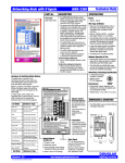
ECL Comfort 200/300 and ECL 2000 HVAC LonWorks®
VI.7F.O1.02
TEST
ECL Comfort 200/300 and ECL 2000 HVAC LonWorks®
Table of Contents
1. Overview
Introduction
About this manual
Assumptions
What you should already know
LonWorks overview
The Lon (Local Operating Network) Concept
Applications
Node arrangements
Message Passing
Collision dectection
Network Management
Routers and bridges
ECL LonWorks node
5
5
5
5
6
6
6
7
7
8
8
9
10
2. Free Topology Network Configuration
Singly terminated bus loop
Doubly terminated bus loop
Star topology
Loop topology
Mixed topology
11
11
11
11
11
3. Free Topology Wiring
System performance and cable selection
Cable parameters
System specifications
Transmission specifications
Doubly-terminated bus topology specifications
Free topology specifications
12
12
12
13
13
13
4. Twisted Pair Network Configuration
Doubly terminated bus topology
13
5. Transformer-Coupled Twisted Pair Wiring
Performance specification
Communication on TP/XF-78 and TP/XF-1250 channels
14
14
6. Cable Specifications
Level 4 cable
Cable suppliers
15
16
7. Service Switch
Service Switch ECL Comfort 200/300
Service Switch ECL 2000
17
17
8. Interface / Network Variables
Interoperability
ECL control
18
VI.7F.O1.02
3
TEST
ECL Comfort 200/300 and ECL 2000 HVAC LonWorks®
1. Overview
Introduction
Portions of this manual are printed with
the permission of the Echelon Corporation
and the National Electrical Contractors
Association of the USA (NECA).
Echelon ®, LonTalk ® , Neuron ® and
LonWorks® are registered trademarks of
the Echelon Corporation.
The documentation in this manual is
About this
manual
This manual is intended to be used both
as an instructional and a reference manual.
It only briefly touches on the basics of
the LonWorks protocol whenever it is
necessary for gaining an understanding of
the LonWorks Option module for the
Danfoss ECL Comfort 200/300 and
Danfoss ECL 2000.
This manual is also intended to serve as
a guideline when you specify and optimize
your communication system. The list of
contents is also a decision route that will
guide you through the decisions you have
to make before you set up your system.
intended to provide you with
comprehensive information on how to
install and set up your LonWorks Option
Card for communication over a LonWorks
communication network.
For more specific information on
installation and operation of the ECL
please refer to the User Manual and
Installation Guide.
Please refer to the manuals:
Technical Manual ECL 2000 LON Option
and LONWorks in ECL Comfort for
detaield and technical information.
Even if you are an experienced LonWorks
programmer, we suggest that you read this
manual in its entirety before you start
programming, since important information
can be found in all sections.
Assumptions
This manual assumes that you are using
a LonWorks Option Card in conjunction
with a Danfoss ECL Comfort 200/300 or
ECL 2000. It is also assumed that you
have a controller node that supports
the interfaces in this document and that
all the requirements stipulated in the
controller node as well as the ECL Comfort
200/300 or ECL 2000 are strictly observed
as well as all limitations therein.
What you
should
already know
The Danfoss LonWorks Option Card is
designed to communicate with any
controller node that supports the interfaces
defined in this document.
It is assumed that you have full knowledge
of the capabilities and limitations of the
controller node.
VI.7F.O1.02
5
ECL Comfort 200/300 and ECL 2000 HVAC LonWorks®
LonWorks
Overview
LonWorks is both an existing standard and
physical hardware developed by Echelon
Corporation.
Echelon's stated goal is to establish a
commodity solution to the presently
daunting problems of designing and
building control networks.
The Lon
(Local
Operating
Network)
Concept
The LonWorks communications structure
is similar to that of a LAN in that messages
are exchanged between a number of
processors continually. LonWorks control
devices are called nodes. The LonWorks
systems are determined Local Operating
Network, or LON. LON technology offers
a means for implementing distributed
systems that perform sensing, monitoring,
control, and other applications.
LON allows intelligent devices, such as
actuators and sensors, to communicate
with one another through an assortment
of communications media using a
standard protocol. LON technology
supports distributed, peer-to-peer
Applications
A key benefit of LonWorks networks is
their ability to communicate across
different types of transmission media in a
single system. The NEURON chip's (the
NEURON chip is the heart of the LonWorks
system) communication port allows for the
use of transceivers for other media (e.g.
coax, fiber optic, etc.) to meet special
needs.
With the proper design, the nodes become
generic building blocks that can be applied
in various ways to control lighting (or any
other task) in many different buildings
using a
VI.7F.O1.02
Customers are currently using LonWorks
for process control, building automation,
engine control, elevator control, life safety
systems, power distribution controls and
similar intelligent building applications.
communications. That is, individual
network devices can communicate
directly with one another, and a central
control system is not required. LON is
designed to move sense and control
messages which are typically very short
and which contain commands and status
information that trigger actions. LON
performance is viewed in terms of
transactions completed per second and
response time. The critical factor in LON
technology is the assurance of correct
signal transmission and verification.
Control systems do not need vast
amounts of data, but they do demand that
the messages they send and receive are
absolutely correct.
variety of communications media. The
tasks which the nodes perform in any
given situation are determined by how they
have been connected and configured.
Because hardware design, software
design, and network design are all
independent in a LonWorks-based system,
a node's function can be programmed
without concern about the specifics of the
networks in which they will be used.
Physically, each node will consist of a
NEURON chip and a transceiver.
6
ECL Comfort 200/300 and ECL 2000 HVAC LonWorks®
LonWorks nodes can be addressed either
Node
Arrangements individually or in groups. A group can
contain up to 64 nodes, and one LonWorks
network can support up to 255 groups.
Furthermore, any node can be part of up
to 15 different groups. A subnet is very
similar to a group, but can contain up to
127 nodes. A domain is the largest
grouping of nodes. A single domain can
handle up to 255 subnets. Thus a single
domain can handle up to 32,385 separate
nodes. A single node may be connected
to no more than two domains.
The group structure has the advantage of
allowing a number of nodes to be reached
Message
Passing
There are a number of trade-offs between
network efficiency, response time,
security, and reliability. Generally,
LonWorks defaults to the greatest degree
of safety and verification for all
communications over the LON network.
The LonTalk protocol (the operating
system that coordinates the LonWorks
system and is built into the chips) offers
four basic types of message service:
The most reliable service is
"acknowledged," or end-to-end
acknowledged service, where a message
is sent to a node or group of nodes and
individual acknowledgments are expected
from each receiver. If an acknowledgment
is not received from all destinations, the
sender times out and re-tries the
transaction. The number of retries and
time-out are both selectable.
Acknowledgments are generated by the
network CPU without intervention of the
application. Transaction IDs are used to
keep track of messages and
acknowledgments so that the application
does not receive duplicate messages.
VI.7F.O1.02
at only one address. This method keeps
the record keeping inside each chip to a
minimum, and allows for faster operating
times. However, individual addressing can
be done at all levels of a LonWorks
system, with high efficiency. The address
table of a node contains entries for the
group type and size, and tells the node
how many acknowledgments to expect
when it sends a message. It also tells the
NEURON chip which domain (the largest
possible grouping of nodes) to use, what
this node's group member number is, (to
identify an acknowledgment as coming
from this node), and contains a transmit
timer, a repeat timer, a retry count, a
receive timer, and the group ID.
An equally reliable service is "request/
response," where a message is sent to a
node or group of nodes and individual
responses are expected from each
receiver. Incoming messages are
processed by the application on the
receiving side before a response is
generated. The same retry and time-out
options
are available as with
acknowledged service. Responses may
include data, so that this service is
particularly suitable for remote procedure
call, or client/server applications.
The next most reliable service is
"unacknowledged repeated," where a
message is sent to a node or a group of
nodes multiple times, and no response is
expected. This service is typically used
when broadcasting to large groups of
nodes and when traffic generated by all
the responses would overload the network.
The least reliable method is
"unacknowledged," where a message is
sent once to a node or group of nodes
and no response is expected. This option
is typically used when the highest
performance is required, network
bandwidth is limited, and the application
is not sensitive to the loss of a message.
7
ECL Comfort 200/300 and ECL 2000 HVAC LonWorks®
Collision
Detection
The LonTalk protocol uses a unique
collision avoidance algorithm (a special
mathematical equation) which allows an
overloaded channel to carry close to its
maximum capacity, rather than have its
throughput reduced due to excessive
collisions between messages. (Collisions
are analogous to 10 people trying to talk
all at once on a single telephone line. The
messages are garbled and confused, and
the contents of the messages are lost.)
When using a communications medium
that supports collision detection (twisted
pair, for example), the LonTalk protocol can
optionally cancel transmission of a packet
as soon as a collision is detected by the
transceiver. This option allows the node
to immediately retransmit any packet that
has been damaged by a collision. Without
collision detection, the node would have
to wait the duration of the retry time to
notice that no acknowledgment was
received, at which time it would retransmit
the packet, assuming knowledge or
request/response
service.
For
unacknowledged service, an undetected
collision means that the packet is not
received and no retry is attempted.
Network
Management
Depending on the level of a given
application, a LonWorks network may or
may not require the use of a Network
Management node. A Network
Management node is a node that has been
specifically designated to perform network
management functions, such as:
• Find unconfigured nodes and download
their network addresses.
• Stop, start, and reset node
applications.
• Access node communication
statistics.
• Configure routers and bridges.
• Download new applications programs.
• Extract the topology of a running
network.
VI.7F.O1.02
8
ECL Comfort 200/300 and ECL 2000 HVAC LonWorks®
Routers and
Bridges
A router (or bridge) is a special node that
consists of two connected NEURON chips,
each connected to a separate channel,
see figure. Routers and bridges pass
packets back and forth between these
channels. There are four types of routers:
A repeater is the simplest form of router,
simply forwarding all packets between the
two channels. Using a repeater, a subnet
can exist across multiple channels. A
bridge simply forwards all packets which
match its domains between the two
channels. Using a bridge, a subnet can
exist across multiple channels. Like a
learning router, a configured router
selectively routes packets between
channels by consulting internal routing
tables. Unlike a learning router, the
contents of the internal routing tables are
specified using Network Management
commands. A learning router monitors the
network traffic and learns the network
topology at the domain/subnet level. The
learning router then uses its knowledge to
selectively route packets between
channels.
Initially, each router sets its internal routing
tables to indicate that all subnets could
lie on either side of the router. Referring to
figure, suppose that node 6 generates a
message bound for node 2. Learning router
1 initially picks up the message.
Examining the source
subnet field of the message, the learning
router notes in its internal routing tables
that subnet 2 lies below it. The router then
compares the source and destination
subnet IDs and since they are different,
the message is passed on. Meanwhile,
learning router 2 has also passed the
message on, making an appropriate
notation in its internal routing tables
regarding the location of subnet 2.
Suppose now that node 2 generates an
acknowledgment. This acknowledgment is
picked up by learning router 1, which now
notes the location of subnet 1. Learning
router 1 examines its internal routing
tables, and noting that subnet 2 lies below,
passes the message on. When the
message appears on subnet 2, it is noted
by both node 6 (the destination node), and
learning router 2, which does not pass it
on but merely notes that subnet 1, like
subnet 2, lies somewhere above. Learning
router 2 will not learn of the existence or
location of subnet 3 until a message is
originated from there. Subnets cannot
cross routers. While bridges and repeaters
allow subnets to span multiple channels,
the two sides of a router must belong to
separate subnets. The fact that routers are
selective about the packets they forward
to each channel can be used to increase
the total capacity of a system in terms of
nodes and connections.
Learning Routers Channel
Source: Echelon Corp.
1
2
3
R
4
Learning
Router 1
Channel
Subnet 1
Learning
Router 2
R
5
6
7
8
Channel
Subnet 2
9
10
11
12
Subnet 3
VI.7F.O1.02
9
ECL Comfort 200/300 and ECL 2000 HVAC LonWorks®
ECL LonWorks The ECL LonWorks option will perform as
an integrated part of the ECL Comfort 200/
Node
300 and ECL 2000. The ECL LonWorks
option will provide unmatched control and
flexibility of the ECL Comfort 200/300 and
ECL 2000 over a variety of LonWorks
Networks.
Addressing nodes on the LonWorks
network is performed at installation time
by an installation tool or network
management tool. Addressing requires the
retrieval of a node's Neuron ID. The Neuron
ID is a 48 bit number that uniquely
identifies every manufactured Neuron chip.
The ECL LonWorks option supports the
three methods of addressing a node:
1. Query and Wink - The LonWorks option
card is shipped with a predefined
domain and subnet. Upon receiving the
wink command, the ECL Comfort 200/
300 and ECL 2000 will flash the total
display so the installer can locate the
node.
2. Service Pin - When the service Pin is
activated via keys on the front, the ECL
LonWorks option will send out it's
Neuron ID over the network.
Binding is the installation time process of
logically connecting one node's output
network variable to another node's input
network variable. To support binding, the
ECL LonWorks option includes the node's
interface file (XIF). The ECL LonWorks
option does not transmit network variables
over the network which are not binded so
there will be no added overhead on the
network.
LonWorks supports many different types
of transmission media. A LonWorks
network physical layer can be: transformer
coupled twisted pair (78 kbps and 1.25
Mbps), free topology, link power, power
line, RF, RS-485, fiber optic, coaxial, and
infrared.
The ECL LonWorks option supports two
transmission media with the versions of
the ECL LonWorks option card:
ECL Comfort and ECL 2000
1. Free topology (FTT-10-A). The free
topology node will also operate on a
link power network.
ECL 2000
2. 78 kpbs transformer coupled twisted
paid (TP/XF-78).
A router is required to interface to a
LonWorks network that is not supported
by the option card versions.
VI.7F.O1.02
10
ECL Comfort 200/300 and ECL 2000 HVAC LonWorks®
2. Free Topology Network Configuration
The FTT system is designed to support
free topology wiring, and will accommodate
bus, star, loop or any combination of these
topologies. FTT-10 transceivers can be
located at any point along the network
wiring.
High capability simplifies system
installation and makes it easy to add
nodes should the system need to be
expanded. The figures present five different
network topologies.
Singly Terminated
Bus Loop
TERMINATION
Doubly Terminated
Bus Loop
TERMINATION
TERMINATION
Star Topology
TERMINATION
Loop Topology
TERMINATION
Mixed Topology
TERMINATION
VI.7F.O1.02
11
ECL Comfort 200/300 and ECL 2000 HVAC LonWorks®
3. Free Topology Wiring
FTT-10 system and transmission
System
Performance specifications are outlined on the following
pages. Both of these specifications should
and
be met to ensure proper operation.
Cable Selection
The transmission specification depends
on such factors as resistance, mutual
capacitance, and the velocity of
propagation.
The system designer may choose a
variety of cables, depending on cost,
availability, and performance. Performance
may vary with cable type.
Echelon will characterize system
performance on the following cable types.
Electrical parameters shown in the table
are typical.
Cable
Parameters
Cable Type
Wire
dia./AWG
Rloop
ý/km
C
nF.km
Belden 85102, single twisted pair,
stranded 9/29, unshielded, plenum
1.3mm/16
28
56
62
Belden 8471, single twisted pair,
stranded 9/29, unshielded, non-plenum
1.3mm/16
28
72
55
Level IV 22AWG, twisted pair,
typically solid & unshielded
0.65mm/22
106
49
67
JY (St) Y 2x2x0.8, 4-wire helical twist,
solid shielded
0.8 mm/20.4
73
98
41
Note that the following specifications are
for one network segment. Multiple
segments may
System
Specifications •
•
be combined using repeaters to increase
the number of nodes and distance.
•
Up to 64 FTT-10 transceivers, or 128
LPT-10 transceivers are allowed per
network segment.
The average temperature of the wire
must not exceed +55°C, although
individual segments of wire may be
as hot as +85°C.
VI.7F.O1.02
Vprop
% of c
Both types of transceivers may be
used on a given segment, provided
that the following constraint is met:
(2 x number of FTT-10 transceivers)
+ (1 x number of LPT-10
transceivers) - 128
12
ECL Comfort 200/300 and ECL 2000 HVAC LonWorks®
Transmission
Specifications
Free Topology nodes run at 78kbps transmission
speeds.
Doubly-Terminated
Bus Topology
Specifications
Maximum bus length for
segments with
FTT-10 tranceivers only
Maximum bus length for
segments with both FTT-10
and LPT-10 transceivers
Belden 85102
2700
2200
Belden 8471
2700
2200
Level IV, 22AWG
1400
1150
JY (St) Y 2x2x0.8
900
750
Units
meters
Free Topology
Specifications
Maximum
node-to-node distance
Maximum
total wire length
Belden 85102
500
500
Belden 8471
400
500
LeveleIV, 22AWG
400
500
JY (St) Y 2x2x0.8
320
500
Units
meters
4. Twisted Pair Network Configuration
TRANSCEIVER
Doubly Terminated
Bus Topology
TERMINATION
TERMINATION
VI.7F.O1.02
13
ECL Comfort 200/300 and ECL 2000 HVAC LonWorks®
5. Transformer-Coupled Twisted Pair Wiring
Performance
Specification
The table provides a summary of the
performance specifications for the 78 kbps
and
Communication
on TP/XF-78
and TP/XF1250
channels;
1.25 Mbps transformer-coupled twisted
pair channels.
Performance
Specifications
Transmission Speed
TP/XF-78 - Only supported
by ECL 2000
supported by any ECL's
78kbps
1.25Mbps
Nodes per Channel
64 (0 to +70°C)
64 (0 to +70°C)
Network Bus Wiring
UL Level IV, 22 AWG (0.65 mm) twisted pair
Network Stub Wiring
UL Level IV, 22 or 24 AWG (0.5 mm) twisted pair
Network Bus Length
Typical 1
Worst case 2
2000m
1330m
500m
125m
Maximum Stub Length 3
3m
0.3m (0 to 70°C)
Network Terminators
Required at both ends of the network
Temperature
Operating
Non-operating
0 to +70°C (64 node load)
–40 to +85°C (44 node load)
0 to +70°C (64 node load)
–20 to +85°C (32 node load)
–40 to +70°C (20 node load)
Electrostatic Discharge
to Network Connectors
No Errors
No Hard Failures
to 15,000V
to 20,000V
to 15,000V
to 20,000V
Isolation between Network
and I/O Connectors
0 - 60Hz (60 seconds)
0 - 60Hz (continuous)
1,000 VRMS
277 VRMS
1,000 VRMS
277 VRMS
1
Typical conditions are 20°C, +5VDC supply
voltage, normal wire temperature, and 64
evenly distributed nodes.
2
Worst case conditions are the combined
effect of worst case conditions of all the above
performance parameters — nodes per
channel, network bus length, stub length,
temperature, etc.
3
The stub length in the table assumes a mutual
capacitance of 17 pF/ft (56 pF/m) for the
twisted pair stub cable. Actual lengths may
be shorter or longer depending on the actual,
measured value.
VI.7F.O1.02
TP/XF-1250 - Not
NOTE:
It is necessary to terminate the ends of a
TP/XF-78 or TP/XF-1250 twisted pair bus
to minimize refelections. Failure to
terminate the bus will degrade network
performance.
14
ECL Comfort 200/300 and ECL 2000 HVAC LonWorks®
6. Cable Specifications
Level 4
Cable
Specifications
The Level 4 cable specification used by
Echelon and as originally defined by the
National Electrical Manufacturers
Association of the USA (NEMA) differs
from the Category IV specification
proposed by the Electronic
Industries Association/Telecommunication
Industry Association (EIA/TIA). The Level
4 cable specifications used by Echelon
are presented below, and are followed by
a list of Level 4 cable suppliers.
Specifications apply to shielded or unshielded 22AWG (0.65mm) cable
24AWG (0.5mm) cable shown in brackets [ ] if different
DC Resistance (Ohms/1000 feet at 20°C)
maximum for a single copper conductor
regardless of whether it is solid or stranded
and is or is not metal-coated.
18.0 [28.6]
DC Resistance Unbalance
(percent) maximum
5
Mutual Capacitance of a Pair
(pF/foot) maximum
17
Pair-to-Ground Capacitance Unbalance
(pF/1000 feet) maximum
1000
Impedance (Ohms)
772kHz
102 ±15% (87-117)
1.0MHz
100 ±15% (85-115)
4.0MHz
100 ±15% (85-115)
8.0MHz
100 ±15% (85-115)
10.0MHz
100 ±15% (85-115)
16.0MHz
100 ±15% (85-115)
20.0MHz
100 ±15% (85-115)
Attenuation (dB/1000 feet at 20°C) maximum
772kHz
4.5 [5.7]
1.0MHz
5.5 [6.5]
4.0MHz
11.0 [13.0]
8.0MHz
15.0 [19.0]
10.0MHz
17.0 [22.0]
16.0MHz
22.0 [27.0]
20.0MHz
24.0 [31.0]
Worst-Pair Near-End Crosstalk (dB) minimum. Values are shown for information only.
The minimum next coupling loss for any pair combination at room temperature is to be
greater than the value determined using the formula NEXT (FMHz) > NEXT (0.772) –
15log10 (FMHz/0.772) for all frequencies in the range of 0.772MHz – 20MHz for a
length of 1000 feet
772kHz
58
1.0MHz
56
4.0MHz
47
8.0MHz
42
10.0MHz
41
16.0MHz
38
20.0MHz
36
VI.7F.O1.02
15
ECL Comfort 200/300 and ECL 2000 HVAC LonWorks®
Level 4
Cable
Suppliers
Anixter stocks the following cables which they will cut to size.
Anixter
Part No.
Description
4711 Golf Road
9D220150
22 AWG (0.65mm) / 1 pair solid, unshielded, PVC
Skokie, IL 60076
9F220150
22 AWG (0.65mm) / 1 pair solid, shielded, PVC
9D220250
22 AWG (0.65mm) / 2 pair solid, unshielded, PVC
Ph: 708-677-2600
9F220254
22 AWG (0.65mm) / 2 pair solid, shielded, PVC
FAX: 708-677-2668
9H2201504
22 AWG (0.65mm) / 1 pair solid, unshielded, plenum
9J2201544
22 AWG (0.65mm) / 1 pair solid, shielded, plenum
9H2202504
22 AWG (0.65mm) / 2 pair solid, unshielded, plenum
9J2202544
22 AWG (0.65mm) / 2 pair solid, shielded, plenum
The following table lists cables stocked by Connect-Air.
Connect-Air
Part No.
Description
International, Inc.
W221P-1002
22 AWG (0.65mm) / 1 pair strand, unshielded, PVC
50-37th Street N.E.
W222P-1004
22 AWG (0.65mm) / 2 pair strand, unshielded, PVC
Auburn, WA 98002
W221P-1003
22 AWG (0.65mm) / 1 pair strand, shielded, PVC
W222P-1005
22 AWG (0.65mm) / 2 pair strand, shielded, PVC
Ph: 206-813-5599
W221P-2001
22 AWG (0.65mm) / 1 pair strand, unshielded, plenum
FAX: 206-813-5699
W221P-2003
22 AWG (0.65mm) / 2 pair strand, unshielded, plenum
W221P-2002
22 AWG (0.65mm) / 1 pair strand, shielded, plenum
W222P-2004
22 AWG (0.65mm) / 2 pair strand, shielded, plenum
Belden
Part No.
Link Power/
8471
Free Topology P.O. Box 1980
Cable
Richmond, IN 47375 85102
Suppliers
Description
16 AWG (1.3mm) / 1 pair strand, unshielded, PVC
16 AWG (1.3mm) / 1 pair strand, unshielded, plenum
Level 4 22AWG
Ph: 206-813-5599
(0.65mm) cables
may also be used.
VI.7F.O1.02
16
ECL Comfort 200/300 and ECL 2000 HVAC LonWorks®
7. Service Switch
Service Switch
ECL Comfort
200/300
When starting up the LON option, a period
of about 30 seconds will elapse during
which the database from the regulator will
be entered. During this starting-up period
it is not possible to come into contact with
the LON option, neither from ECL Comfort
nor from the network. The starting-up
period will occur on reset/power up
regulator/LON option and when an
application change is made in ECL
Comfort.
After starting up, the following parameters
can be activated via the ECL Comfort MMI
interface:
Parameter 196 in circuit 1 is the service
pin.
Parameter 197 in circuit 1 is the LON option
reset.
Parameter 196 and 197 can be accessed
by scrolling down through the parameters
on the installer page (grey page) with the
arrow keys. The parameters can be
activated/deactivated with the +/- keys
(see instructions).
At wink, the display will flash until any key
is pressed on ECL Comfort.
When updating parameters in ECL
Comfort the values must lie in a workable
range. If they fall outside the range they
will be rejected.
Service Switch When the service pin of the LON device
is activated, the device broadcasts its
ECL 2000
Neuron ID onto the network. To activate
the ECL 2000’s service pin:
1. In the System Overview
picture,
press to access the
CommonFunctions service menu.
2. Press
until Communication
is selected.
3. Press
to access the
Communication picture shown to
the left.
4. Press
to activate the service
pin.
Depending on the setup of the ECL
2000, you may be required to enter an
access code before the service pin can
be activated. See the ECL 2000 User’s
Guide (ref. [1]) for instructions on
entering the access code.
VI.7F.O1.02
17
ECL Comfort 200/300 and ECL 2000 HVAC LonWorks®
8. Interface / Network Variables
Interoperability Interoperability refers to the ability of
independent nodes to operate together
over the LonWorks network. The LonMark
program was developed to address
interoperability issues. The Lonworks
option supports the following LonMark
activities to improve interoperability:
1. Standard Network Variable Types
(SNVT's); SNVT's define the units,
limits and resolution of network
variables so that nodes have a
common platform for representing
data items. The LonWorks option
only uses SNVT's to transmit and
receive data over the LonWorks
network.
2. Standard Objects;
Standard Objects are a collection of
SNVT's to perform a function. The
LonWorks option supports the node
object and a controller standard object
as defined in the LonMark
Interoperability guidelines 2.0.
3. LonMark Interoperability Association
Tast Groups (LonUsers
Groups); Tast groups define
SNVT's and standard objects to
create standards and models to be
used by particular applications.
Danfoss is active in defining
standards for LonUser groups.
ECL Control
The ECL LonWorks option supports all
SNVT's for flexible control of the ECL over
the LonWorks network.
Please refer to the manuals:
Technical Manual ECL 2000 LON Option
and LONWorks in ECL Comfort for
detaield and technical information.
VI.7F.O1.02
18
ECL Comfort 200/300 and ECL 2000 HVAC LonWorks®
VI.7F.O1.02
19
ECL Comfort 200/300 and ECL 2000 HVAC LonWorks®
VI.7F.O1.02
20