1
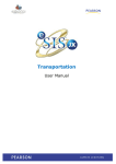
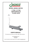
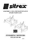
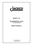
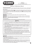
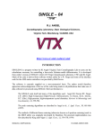
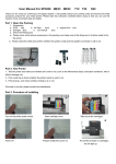
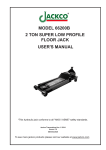
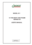
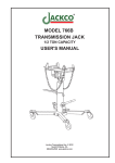
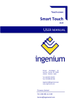
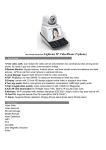
MODEL 820A
AIR HYDRAULIC JACK
USER'S MANUAL
Features:
• Air- operated hydraulic service jack.
• Professional use in repairing
trucks, trailer buses and heavy duty
vehicles.
• Air pressure range: 90-120 PSI
• Lock air valve by “U” lock without
having to push the push plate all the
time.
• Handle can be adjusted 3 different
angles by lifting lock lever.
• Extension saddle included.
Jackco Transnational Inc. © 2009
South El Monte, CA
888-452-2526 www.jackco.com
FOR YOUR SAFETY
Read all instructions, warnings and cautions carefully. Follow all safety precautions to avoid personal injury
or property damage during system operation. Jackco cannot be responsible for damage or injury resulting
from unsafe product use, lack of maintenance or incorrect product and/or system operation. Contact Jackco
when in doubt as to the safety precautions and operations.
Failure to comply with the following cautions and warnings could cause equipment damage and personal
injury.
• Stay clear of loads supported by hydraulics.
A cylinder, when used as a load lifting device,
should never be used as a load holding device.
After the load had been raised or lowered,
it must always be blocked mechanically.
• Do not exceed equipment rating never attempt
to lift a load weighing more than the capacity
of the cylinder. Overloading causes equipment
failure and possible personal injury. The
cylinders are designed for a maximum pressure
of 10,000 psi. Do not connect a jack or cylinder
to a pump with a higher pressure rating.
• The system operating pressure must not
exceed the pressure rating of the lowest
rated component in the system. Install
pressure gauges in the system to monitor
operating pressure. It is your window
to what is happening in the system.
• B E S U R E S E T U P I S S TA B L E B E F O R E
LIFTING LOAD.
Cylinders should be placed on a flat
surface that can support the load. Where
applicable, use a cylinder base for added
stability. Do not weld or otherwise modify the
cylinder to attach a base or other support.
• Avoid situations where loads are not directly
centered on the cylinder plunger. Off-center
loads produce considerable strain on cylinders
and plungers. In addition, the load may slip
or fall, causing potentially dangerous results.
• Immediately replace worn or damaged parts
genuine JACKCO parts. Standard grade parts
will break causing personal injury and property
damage. JACKCO parts are designed to fit
properly and withstand high loads.
•To avoid personal injury keep hands and feet away
from cylinder and work piece during operation.
•NEVER set the relief valve to a higher pressure
than the maximum rated pressure of the pump.
Higher settings may result in equipment damage
and/or personal injury. Do no remove relief valve.
•Keep hydraulic equipment away from flames and
heat. Excessive heat will soften packing and seals,
resulting in fluid leaks. Heat also weakens hose
materials and packings. For optimum performance
do not expose equipment to temperatures of 150°F
or higher. Protect hoses and cylinders from weld
spatter.
•Hydraulic equipment must only be serviced by a
qualified hydraulic technician. For repair service,
contact JACKCO Inc. To protect your warranty, use
only JACKCO hydraulic oil.
ASSEMBLING INSTRUCTION
1. Insert (#027) saddle into the ram to increase contact surface. Replace with (#028)
extension saddle to extend the lifting height.
2. Insert handle assembly into handle fork and tighten it with (1#03) set screw and (#098)
spring washer.
3. To lift, turn knob clockwise and connect air valve to 90-120 PSI air source.
4. To lower, turn knob counterclockwise and ram will self-retract.
DIMENSIONS
Exploded View
Parts List Next Page
Parts List
Part No.
001A
008
009
026
027
028
030A
062
064
065
067
080
081
082
083
084
086
087
090
092
093
094
095
096
097
098
100
111
102
103
104
105
Description
Cylinder Assembly
Seal
Bolt
Snap- ring "C"
Saddle
Extension Saddle
Pump assembly
Bolt
O-ring
Back-up Ring
Conical Spring Washer
Universal Joint
Spring Pin
Spring Pin
Union Pipe
Spring Pin
Chassis
Right Side Plate Assembly
Left Side Plate Assembly
Bolt
Spring Washer
Bolt
Spring Washer
Fixed Bracket Angle
Bolt
Spring Washer
Handle Fork
Connecting Spindle
Split Pin
Set Screw
Cover
Bolt
Q'ty
1
1
1
2
1
1
1
4
3
1
4
2
1
2
1
1
1
1
1
4
4
4
4
1
4
5
1
1
1
1
1
4
Part No.
107
108
109
110
111
112
113
114
115
116
117
118
119
120
123
125
126
127
128
130
131
132
133
135
136
137
139
140
141
142
143
Description
Tire
Washer
Snap-ring "C"
Air Valve Body
Spring
Stem
O-ring
Seal
O-ring
Bolt
Push Plate
U Lock
Spring Pin
Screen
Joint
Joint
Hose
8-ring
Clamp, Hose
Handle
Release Rod
Turn Knob
Spring Spin
Adjustable Rod
Spring
Washer
Split Pin
Lock Lever
Spring Pin
Bolt
Grip
Q'ty
2
2
2
1
1
1
1
1
1
1
1
1
1
1
1
1
1
1
2
1
1
1
1
1
1
2
1
1
1
2
2
Exploded View of Cylinder Unit
Part No.
001
010
012
013
014
015
016
017
Description
Base Assembly
Ram
Cup Seal
Busing Ram
Snap-Ring "C"
Screw with sleeve
Filter Screen
O-ring
Q'ty
1
1
1
1
1
1
1
2
Part No.
018
019
020
022
023
024
025
029
Description
Reservoir
Head Nut
Seal
Support
Recovery Spring
Flat Head Bolt
Nut
Cup Washer
Q'ty
1
1
1
1
4
4
4
1
Exploded View of Pump Unit
Part No.
030
031
032
033
034
035
036
037
038
039
040
041
042
043
044
045
046
047
050
051
053
054
Description
Base Pump
Ball ø 1/4"
Stem
Ball ø 3/8"
Spring
Washer
Bolt
Washer
Double End Fitting
O-ring
Back-up Ring
Washer
Nut
Spring
Washer
Plunger
Piston
O-ring
Pump Body
Ring with Seal
Valve Stem
Cup Seal
Q'ty
1
1
1
1
1
1
1
2
1
1
1
1
1
1
1
1
1
1
1
1
1
1
Part No.
056
057
058
059
060
062
063
068
069
070
072
073
074
075
076
077
144
145
146
147
008
009
Description
Bolt
Toothed Lock Washer
Gascket
Cover Pump
Bolt
Blot
Spring Washer
Fliter
Fliter
Elbow Joint
Body Rlease Valve
O- ring
Release Valve
O-ring
Fixed Washer
Snap- Ring "C"
Ball ø 7/32"
Spring Plunger
Spring
Screw Spring
Seal
Bolt
Q'ty
1
1
1
1
3
4
4
1
1
1
1
1
1
1
1
1
1
1
1
1
1
1
Notes
LIMITED ONE YEAR WARRANTY
Jackco Transnational Inc. warrants all Jackco equipment and tools to the original purchaser against any manufacturing defect in material or
workmanship for a period of one (1) year from the original date of purchase. If the defective equipment or tool is determined to be covered under
this warranty, it shall be repaired or replaced at manufacturer's discretion without charge, provided that the equipment or tool must be returned
with proof of purchase to the dealer and freight prepaid, if returned to the manufacturer. This warranty shall not apply to damage due to accident,
negligent use, and lack of maintenance, abuse or applications other than the specific function the equipment or tool is designed for.
No other warranties, expressed or implied, including those of merchantability or fitness for particular purpose shall be applicable to Jackco
except as specifically stated herein. In no event shall Jackco be liable to any party for any special, direct, indirect, consequential, punitive
damage of any nature caused by the sale or use of the equipment or tool.
Note: This warranty gives the original purchaser specific legal rights which may very from state to state.
Jackco Transnational Inc. © 2009
South El Monte, CA
888-452-2526 www.jackco.com