1
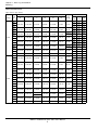
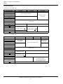
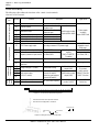
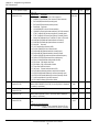
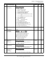
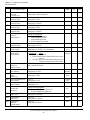
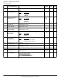
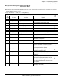
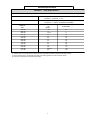
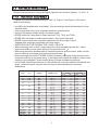
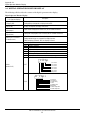
Table A2-1. Standard Specifications (Continued)
SECTION
B. GPD
ALL
P5M
SECTION
C. ALL
506s
Control Method
Sine Wave PWM
Digital command: 0.01%
(-10 to 40oC)
(+14 to 104oF)
Analog command: 0.1%
(15 to 35oC)
(59 to 95oF)
Frequency Regulation
Control
Characteristics
Frequency Resolution
Digital Operator reference: 0.1 Hz
Analog reference: 0.06 Hz/60Hz
Output Frequency Resolution
0.01 Hz
Frequency Setting Signal
0 to 10 VDC (20K Ohms), 4-20mA (250 Ohms)
Accel / Decel Time
0.1 to 3600 sec
(Accel / Decel time setting independently)
Braking Torque
Approximately 20%
V/F Pattern Selection
1 Preset Pattern:
1 Custom Pattern: defined by parameter settings.
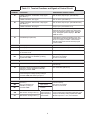
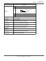
Protective
Functions
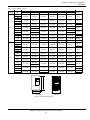
Motor Overload Protection
Electronic thermal overload relay
Instantaneous Overcurrent
Motor coasts to a stop at approximately 180% rated current
Fuse Blown Protection
Motor coasts to a stop by blown fuse.
Overload
Motor coasts to a stop after 60 sec. of a 120% overload condition.
Overvoltage
Motor coasts to a stop if drive DC bus voltage exceeds 1050VDC.
Undervoltage
Motor coasts to a stop if drive DC bus voltage drops to
546 VDC or below.
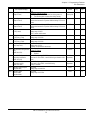
Momentary Power Failure
Factory setting provides for motor to coast to a stop after
momentary power failure of more than 15 ms. Can be
reprogrammed to allow continuous operation (ride-through)
during power failure of up to 2 seconds or longer.
Heatsink Overheat
Thermoswitch
Stall Prevention
Stall prevention at acceleration /deceleration and constant
speed operation.
Ground Fault
Provided by electronic circuit.
Power Charge Indication
"CHARGE" lamp remains lit until bus voltage drops below 50 V.
2