1
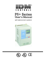
P5+ Series
User’s Manual
(with alphanumeric operator)
CE
!
WARNING
PRECAUTIONS
1) Read this manual in its entirety before installing or operating the P5+ inverter. This manual applies to inverters
with software versions 5110 / 5120 or later only and is not intended to be used in conjunction with any other software.
2) Do not connect or disconnect wiring, or perform signal checks while the power supply is turned ON.
3) The P5+ internal capacitor may be charged even after the power supply is turned OFF. To prevent electrical shock,
disconnect all power before servicing the inverter. Then wait at least five minutes after the power supply is disconnected and all LEDs are extinguished.
4) Do not perform a withstand voltage test or a megger test on any part of the P5+. This electronic equipment uses
semiconductors and is vulnerable to high voltage.
5) Do not remove the operator unless the power supply is turned OFF. Never touch the printed control board while the
power supply is turned ON.
6) The P5+ is suitable for use on a circuit capable of delivering not more than 65,000 RMS symmetrical amperes, 480
Volts maximum (460V class units), 240 Volts maximum (230V class units).
Failure to observe these and other precautions highlighted in this manual will expose the user to high voltages, resulting in equipment damage, serious injury or death.
NOTICE
Printed April,1999. The information contained within this document is the proprietary property of IDM Controls, and
may not be copied, reproduced or transmitted to other parties without the expressed written authorization of IDM Controls.
No patent liability is assumed with respect to the use of the information contained herein. Moreover, because improvements are constantly being made to our high-quality products, the information contained in this manual is subject to
change without notice. Every precaution has been taken in the preparation of this manual. Nevertheless, IDM assumes
no responsibility for errors or omissions. Neither is any liability assumed for damages resulting from the use of the
information contained in this publication.
IDM P5+ Installation & Quick Start User’s Manual
2
Contents
CONTENTS
Section
Description
Page
1
RECEIVING & INSTALLATION
1.1
1.2
INTRODUCTION . . . . . . . . . . . . . . . . . . . . . . . . . . . . . . . . . . . . . . . . . . . . . . . . . . . . . . . . . . . . . . . . . . . . 5
SPECIFICATIONS . . . . . . . . . . . . . . . . . . . . . . . . . . . . . . . . . . . . . . . . . . . . . . . . . . . . . . . . . . . . . . . . . . . 6
230 V. . . . . . . . . . . . . . . . . . . . . . . . . . . . . . . . . . . . . . . . . . . . . . . . . . . . . . . . . . . . . . . . . . . . . . . . . . 6
460 V. . . . . . . . . . . . . . . . . . . . . . . . . . . . . . . . . . . . . . . . . . . . . . . . . . . . . . . . . . . . . . . . . . . . . . . . . . 7
PRELIMINARY INSPECTION. . . . . . . . . . . . . . . . . . . . . . . . . . . . . . . . . . . . . . . . . . . . . . . . . . . . . . . . . . . 8
Receiving . . . . . . . . . . . . . . . . . . . . . . . . . . . . . . . . . . . . . . . . . . . . . . . . . . . . . . . . . . . . . . . . . . . . . . 8
Checking the Nameplate . . . . . . . . . . . . . . . . . . . . . . . . . . . . . . . . . . . . . . . . . . . . . . . . . . . . . . . . . . 8
Identifying the Parts . . . . . . . . . . . . . . . . . . . . . . . . . . . . . . . . . . . . . . . . . . . . . . . . . . . . . . . . . . . . . . 9
MOUNTING . . . . . . . . . . . . . . . . . . . . . . . . . . . . . . . . . . . . . . . . . . . . . . . . . . . . . . . . . . . . . . . . . . . . . . 10
Precautions . . . . . . . . . . . . . . . . . . . . . . . . . . . . . . . . . . . . . . . . . . . . . . . . . . . . . . . . . . . . . . . . . . . . 10
Choosing a Location. . . . . . . . . . . . . . . . . . . . . . . . . . . . . . . . . . . . . . . . . . . . . . . . . . . . . . . . . . . . . 10
Removing and Replacing the Digital Operator. . . . . . . . . . . . . . . . . . . . . . . . . . . . . . . . . . . . . . . . 11
Removing and Replacing the Front Cover . . . . . . . . . . . . . . . . . . . . . . . . . . . . . . . . . . . . . . . . . . . 11
Dimensions/Heat Loss . . . . . . . . . . . . . . . . . . . . . . . . . . . . . . . . . . . . . . . . . . . . . . . . . . . . . . . . . . . 12
Clearances. . . . . . . . . . . . . . . . . . . . . . . . . . . . . . . . . . . . . . . . . . . . . . . . . . . . . . . . . . . . . . . . . . . . . 14
WIRING . . . . . . . . . . . . . . . . . . . . . . . . . . . . . . . . . . . . . . . . . . . . . . . . . . . . . . . . . . . . . . . . . . . . . . . . . 15
Precautions . . . . . . . . . . . . . . . . . . . . . . . . . . . . . . . . . . . . . . . . . . . . . . . . . . . . . . . . . . . . . . . . . . . . 15
Inspection . . . . . . . . . . . . . . . . . . . . . . . . . . . . . . . . . . . . . . . . . . . . . . . . . . . . . . . . . . . . . . . . . . . . . 15
P5+ Standard Connection Diagram. . . . . . . . . . . . . . . . . . . . . . . . . . . . . . . . . . . . . . . . . . . . . . . . . 16
Main Circuit Wiring. . . . . . . . . . . . . . . . . . . . . . . . . . . . . . . . . . . . . . . . . . . . . . . . . . . . . . . . . . . . . 18
Terminal Functions. . . . . . . . . . . . . . . . . . . . . . . . . . . . . . . . . . . . . . . . . . . . . . . . . . . . . . . . . . . . . . 20
Wire and Terminal Screw Sizes . . . . . . . . . . . . . . . . . . . . . . . . . . . . . . . . . . . . . . . . . . . . . . . . . . . 21
Control Circuit Wiring . . . . . . . . . . . . . . . . . . . . . . . . . . . . . . . . . . . . . . . . . . . . . . . . . . . . . . . . . . . 24
1.3
1.4
1.5
2
OPERATION
2.2
2.3
2.4
Precautions . . . . . . . . . . . . . . . . . . . . . . . . . . . . . . . . . . . . . . . . . . . . . . . . . . . . . . . . . . . . . . . . . . . . 25
TRIAL OPERATION . . . . . . . . . . . . . . . . . . . . . . . . . . . . . . . . . . . . . . . . . . . . . . . . . . . . . . . . . . . . . . . . 26
Digital Operator Display at Power-up. . . . . . . . . . . . . . . . . . . . . . . . . . . . . . . . . . . . . . . . . . . . . . . 26
Operation Checkpoints. . . . . . . . . . . . . . . . . . . . . . . . . . . . . . . . . . . . . . . . . . . . . . . . . . . . . . . . . . . 26
Basic Operation . . . . . . . . . . . . . . . . . . . . . . . . . . . . . . . . . . . . . . . . . . . . . . . . . . . . . . . . . . . . . . . . 26
DIGITAL OPERATOR DISPLAY . . . . . . . . . . . . . . . . . . . . . . . . . . . . . . . . . . . . . . . . . . . . . . . . . . . . . . . 30
LED DESCRIPTION . . . . . . . . . . . . . . . . . . . . . . . . . . . . . . . . . . . . . . . . . . . . . . . . . . . . . . . . . . . . . . . . 31
OPERATION MODE SELECTION . . . . . . . . . . . . . . . . . . . . . . . . . . . . . . . . . . . . . . . . . . . . . . . . . . . . . . 32
3
PROGRAMMING FEATURES
3.1
3.2
3.3
P5+ PARAMETERS (n001~n116) . . . . . . . . . . . . . . . . . . . . . . . . . . . . . . . . . . . . . . . . . . . . . . . . . . . . . 33
PARAMETER SET-UP & INITIALIZATION . . . . . . . . . . . . . . . . . . . . . . . . . . . . . . . . . . . . . . . . . . . . . . . 43
P5+ OPERATION . . . . . . . . . . . . . . . . . . . . . . . . . . . . . . . . . . . . . . . . . . . . . . . . . . . . . . . . . . . . . . . . . . 44
Accel/decel time adjustment . . . . . . . . . . . . . . . . . . . . . . . . . . . . . . . . . . . . . . . . . . . . . . . . . . . . . . 44
Automatic fault retry . . . . . . . . . . . . . . . . . . . . . . . . . . . . . . . . . . . . . . . . . . . . . . . . . . . . . . . . . . . . 44
Automatic restart after momentary power loss. . . . . . . . . . . . . . . . . . . . . . . . . . . . . . . . . . . . . . . . 45
Carrier frequency . . . . . . . . . . . . . . . . . . . . . . . . . . . . . . . . . . . . . . . . . . . . . . . . . . . . . . . . . . . . . . . 45
Current limit (Stall prevention) . . . . . . . . . . . . . . . . . . . . . . . . . . . . . . . . . . . . . . . . . . . . . . . . . . . . 46
2.1
IDM P5+ Installation & Quick Start User’s Manual
3
Contents
3.4
4
4.1
4.2
DC injection braking . . . . . . . . . . . . . . . . . . . . . . . . . . . . . . . . . . . . . . . . . . . . . . . . . . . . . . . . . . . .
Energy savings control . . . . . . . . . . . . . . . . . . . . . . . . . . . . . . . . . . . . . . . . . . . . . . . . . . . . . . . . . .
Frequency agree set point . . . . . . . . . . . . . . . . . . . . . . . . . . . . . . . . . . . . . . . . . . . . . . . . . . . . . . . .
Frequency meter or ammeter . . . . . . . . . . . . . . . . . . . . . . . . . . . . . . . . . . . . . . . . . . . . . . . . . . . . .
Frequency meter or ammeter calibration . . . . . . . . . . . . . . . . . . . . . . . . . . . . . . . . . . . . . . . . . . . .
Frequency signal adjustment. . . . . . . . . . . . . . . . . . . . . . . . . . . . . . . . . . . . . . . . . . . . . . . . . . . . . .
Jog operation . . . . . . . . . . . . . . . . . . . . . . . . . . . . . . . . . . . . . . . . . . . . . . . . . . . . . . . . . . . . . . . . . .
Jump frequencies . . . . . . . . . . . . . . . . . . . . . . . . . . . . . . . . . . . . . . . . . . . . . . . . . . . . . . . . . . . . . . .
MODBUS communication . . . . . . . . . . . . . . . . . . . . . . . . . . . . . . . . . . . . . . . . . . . . . . . . . . . . . . .
Motor overload detection . . . . . . . . . . . . . . . . . . . . . . . . . . . . . . . . . . . . . . . . . . . . . . . . . . . . . . . .
Multi-step speed selection. . . . . . . . . . . . . . . . . . . . . . . . . . . . . . . . . . . . . . . . . . . . . . . . . . . . . . . .
Phase loss detection. . . . . . . . . . . . . . . . . . . . . . . . . . . . . . . . . . . . . . . . . . . . . . . . . . . . . . . . . . . . .
PID Control . . . . . . . . . . . . . . . . . . . . . . . . . . . . . . . . . . . . . . . . . . . . . . . . . . . . . . . . . . . . . . . . . . .
Reverse run prohibit . . . . . . . . . . . . . . . . . . . . . . . . . . . . . . . . . . . . . . . . . . . . . . . . . . . . . . . . . . . .
Soft-start characteristics . . . . . . . . . . . . . . . . . . . . . . . . . . . . . . . . . . . . . . . . . . . . . . . . . . . . . . . . .
Speed limit adjustment . . . . . . . . . . . . . . . . . . . . . . . . . . . . . . . . . . . . . . . . . . . . . . . . . . . . . . . . . .
Stopping method . . . . . . . . . . . . . . . . . . . . . . . . . . . . . . . . . . . . . . . . . . . . . . . . . . . . . . . . . . . . . . .
Torque adjustment. . . . . . . . . . . . . . . . . . . . . . . . . . . . . . . . . . . . . . . . . . . . . . . . . . . . . . . . . . . . . .
Torque detection . . . . . . . . . . . . . . . . . . . . . . . . . . . . . . . . . . . . . . . . . . . . . . . . . . . . . . . . . . . . . . .
Tripless operation . . . . . . . . . . . . . . . . . . . . . . . . . . . . . . . . . . . . . . . . . . . . . . . . . . . . . . . . . . . . . .
V/f pattern adjustment. . . . . . . . . . . . . . . . . . . . . . . . . . . . . . . . . . . . . . . . . . . . . . . . . . . . . . . . . . .
Slip compensation . . . . . . . . . . . . . . . . . . . . . . . . . . . . . . . . . . . . . . . . . . . . . . . . . . . . . . . . . . . . . .
INPUTS & OUTPUTS . . . . . . . . . . . . . . . . . . . . . . . . . . . . . . . . . . . . . . . . . . . . . . . . . . . . . . . . . . . . . . .
Multi-function input signals . . . . . . . . . . . . . . . . . . . . . . . . . . . . . . . . . . . . . . . . . . . . . . . . . . . . . .
Analog input signals . . . . . . . . . . . . . . . . . . . . . . . . . . . . . . . . . . . . . . . . . . . . . . . . . . . . . . . . . . . .
Multi-function output signals . . . . . . . . . . . . . . . . . . . . . . . . . . . . . . . . . . . . . . . . . . . . . . . . . . . . .
47
48
49
49
50
50
51
52
52
53
55
56
56
57
58
59
59
61
62
63
64
65
66
66
69
71
DIAGNOSTICS
Precautions. . . . . . . . . . . . . . . . . . . . . . . . . . . . . . . . . . . . . . . . . . . . . . . . . . . . . . . . . . . . . . . . . . . .
MAINTENANCE & INSPECTION . . . . . . . . . . . . . . . . . . . . . . . . . . . . . . . . . . . . . . . . . . . . . . . . . . . . . .
Periodic Inspection . . . . . . . . . . . . . . . . . . . . . . . . . . . . . . . . . . . . . . . . . . . . . . . . . . . . . . . . . . . . .
Parts Replacement Schedule. . . . . . . . . . . . . . . . . . . . . . . . . . . . . . . . . . . . . . . . . . . . . . . . . . . . . .
ALARM & FAULT DISPLAY . . . . . . . . . . . . . . . . . . . . . . . . . . . . . . . . . . . . . . . . . . . . . . . . . . . . . . . . .
Alarm Display . . . . . . . . . . . . . . . . . . . . . . . . . . . . . . . . . . . . . . . . . . . . . . . . . . . . . . . . . . . . . . . . .
Fault Display . . . . . . . . . . . . . . . . . . . . . . . . . . . . . . . . . . . . . . . . . . . . . . . . . . . . . . . . . . . . . . . . . .
Motor Faults. . . . . . . . . . . . . . . . . . . . . . . . . . . . . . . . . . . . . . . . . . . . . . . . . . . . . . . . . . . . . . . . . . .
73
74
74
74
75
75
75
78
A
APPENDIX
A-1
A-2
A-3
BRAKING CONNECTION DIAGRAMS . . . . . . . . . . . . . . . . . . . . . . . . . . . . . . . . . . . . . . . . . . . . . . . . . . 79
DIGITAL OPERATOR MONITOR DISPLAY . . . . . . . . . . . . . . . . . . . . . . . . . . . . . . . . . . . . . . . . . . . . . . 80
CE CONFORMANCE . . . . . . . . . . . . . . . . . . . . . . . . . . . . . . . . . . . . . . . . . . . . . . . . . . . . . . . . . . . . . . . 82
IDM P5+ Installation & Quick Start User’s Manual
4
Chapter 1 - Rece v ng & Installat on
- Chapter 1 -
RECEIVING & INSTALLATION
1.1 INTRODUCTION
The P5+ is a series of high quality, variable torque inverters. With a power range of .75 to 500 HP, it provides all the
functionality of prior series, in a compact, low cost package. This functionality includes proprietary features like fullrange automatic torque boost, electronic thermal motor overload, energy savings and PID operation, low-noise operation and various other features. It also features a new digital operator for simple programming. Utilizing the latest
microprocessor technology, members of the design team have collaborated to make the P5+ the world’s first optimized
inverter specifically designed for variable torque applications.
This manual details installation, start-up and operating procedures for the P5+ series adjustable frequency drive controller. Descriptions of diagnostic and troubleshooting procedures are also included herein.
IDM P5+ Installation & Quick Start User’s Manual
5
Chapter 1 - Rece v ng & Installat on
Specifications
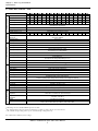
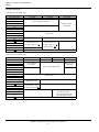
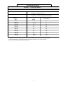
1.2 SPECIFICATIONS - 230V
Environmental Conditions
Protective Functions
Control Characteristics
Power Supply
Output Characteristics
Inverter Model P5UMotor Output (HP) *
Capacity (kVA)
Rated Output Current (A)-VT**
Rated Output Current (A)-CT**
Max. Voltage #
Rated Output Frequency
Overload Capacity - VT **
Overload Capacity - CT **
Input Current (A)
Rated Voltage &
Frequency #
Voltage Fluctuation
Frequency Fluctuation
Control Method
Frequency Control Range
Frequency Accuracy
Frequency Setting Resolution
Output Frequency Resolution
Frequency Setting
Accel/Decel Time
Braking Torque
No. of V-f Patterns
Motor Overload Protection
Instantaneous Overcurrent
Fuse Protection
Overload
Overvoltage
Undervoltage
20P4 20P7 21P5 22P2 23P7 25P5 27P5 2011 2015 2018 2022 2030
0.5
1
2
3
5
7.5
10
20
25
30
40
50
1.2
2.3
3.0
4.2
6.7
9.5
13
19
24
30
37
50
3.2
6
8
11 17.5 27
36
54
68
80
104 130
3.2
6
8
11 17.5 25
33
49
64
64
83
104
3-Phase, 200/208/220/230V
(Proportional to input voltage)
0.1 to 400 Hz
120% Rated Output Current for 1 minute
150% Rated Output Current for 1 minute
3.9
7.2
9.6 13.2 21
33
44
65
82
88
119 143
3-Phase
220 - 230V, 50/60Hz
+10%, -15%
±5%
Sine wave PWM with full-range, automatic torque boost
0.1 to 400 Hz
Digital command: 0.01%, Analog command: 0.1%
Digital Operator Reference: 0.1Hz,
Analog Reference: 0.06Hz (@60Hz)
0.01 Hz
0 to +10VDC (20kΩ), 4-20mA (250Ω)
0.0 to 3600.0 sec.
(Accel/Decel time setting independently: 0.1 sec )
Approx. 20%
1 preset V/f pattern and 1 custom pattern
2037
60
61
160
128
2045
75
70
192
154
2055
100
85
248
198
2075
125
110
312
250
176
212
270
344
Electronic thermal overload relay (I2T)
Motor coasts to stop at approx. 200% rated output current.
Motor coasts to stop at blown fuse.
Motor coasts to stop after 1 min. at rated overload capacity.
Motor coasts to a stop if converter output voltage exceeds 410VDC (820VDC at 460V input)
Motor coasts to stop if converter output voltage drops below user adjustable value
Immediate stop after 15 ms or longer power loss.
(Continuous system operation during power loss less than 2 sec is equipped as standard.)
Momentary Power Loss
Heatsink Overheat
Stall Prevention
Ground Fault
Power Charge Indication
Input Phase Loss
Location
Ambient
Temperature
Storage
Temperature
Humidity
Vibration
Thermistor - OH1, OH2
Stall prevention at acceleration/deceleration and constant speed operation
Provided by electronic circuit
Charge LED stays on until voltage drops below 50VDC
Single-phase protection
Indoor (protected from corrosive gases and dust)
+14 to 104°F (-10 to 40°C) for NEMA 1 type (not frozen)
+14 to 113°F (-10 to 45°C) for open chassis type
-4 to 140°F (-20 to 60°C)
95% RH (non-condensing)
9.8m/s2 (1G) less than 20Hz, up to 1.96m/s2 (0.2G) at 20 to 50Hz
* HP ratings based on standard NEMA 4-pole motor data.
#
For 380V operation, the motor rated current must be less than or equal to the inverter rated current.
** VT: Variable Torque rating (n116=1), CT: Constant Torque rating (n116=0)
Note: Shaded areas indicate factory settings.
IDM P5+ Installation & Quick Start User’s Manual
6
Chapter 1 - Rece v ng & Installat on
Specifications
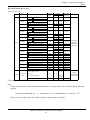
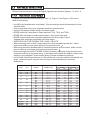
SPECIFICATIONS - 460V
Output Characteristics
Inverter Model P5UMotor Output (HP) *
Capacity (kVA)
Rated Output
Current (A)-VT**
Rated Output
Current (A)-CT**
40P4 40P7 41P5 42P2 43P7 44P0 45P5 47P5 4011 4015 4018 4022 4030 4037 4045 4055 4075 4110 4160 4185 4220 4300
0.5 1
2
3
5 7.5 10 15 20 25 30 40 50 60 75 100 150 200 250 300 400 500
1.4 2.6 3.7 4.7 6.1 8.6 11 14 21 26 31 40 50 61 73 98 130 170 230 260 340 460
1.9
3.6
5.1
6.6
8.5 11.7 14.8 21.0 28.6 34.0 41
52
65
80
96
128 180 240 302 380 506 675
1.9
3.6
5.1
6.6
8.5 11.7 14.8
42
52
64
77
102 144 182 242 304 404 540
Max. Voltage #
Rated Output Frequency
Control Characteristics
Power Supply
Overload Capacity-VT**
Overload Capacity-CT**
Input Current (A)
Rated Voltage &
2.3
4.3
6.1
8
10.2
14
Frequency #
Voltage Fluctuation
Frequency Fluctuation
Control Method
Frequency Control Range
Frequency Accuracy
Frequency Setting
Resolution
Output Freq Resolution
Frequency Setting
Accel/Decel Time
Braking Torque
No. of V-f Patterns
Environmental Conditions
Protective Functions
Motor Overload Protection
Instantaneous Overcurrent
Fuse Protection
Overload
Overvoltage
Undervoltage
Momentary Power Loss
Heatsink Overheat
18 28.6 34
32
3-Phase, 380/400/415/440/460V
(Proportional to input voltage)
0.1 to 400 Hz
120% Rated Output Current for 1 minute
(Model 47P5 is rated 150% / 1 minute)
150% Rated Output Current for 1 minute
17.8 26 35 40 46 58 72 88 106 141 198 264 330 456 608 810
3-Phase
380 -440 - 460V, 50/60Hz
+10%, -15%
±5%
Sine wave PWM with full-range, automatic torque boost
0.1 to 400 Hz
Digital command: 0.01%, Analog command: 0.1%
Digital Operator Reference: 0.1Hz,
Analog Reference: 0.06Hz (@60Hz)
0.01 Hz
0 to +10VDC (20kΩ), 4-20mA (250Ω)
0.0 to 3600.0 sec.
(Accel/Decel time setting independently: 0.1 sec )
Approx. 20%
1 preset V/f pattern and 1 custom pattern
Electronic thermal overload relay (I2T)
Motor coasts to stop at approx. 200% rated output current.
Motor coasts to stop at blown fuse.
Motor coasts to stop after 1 min. at rated overload capacity.
Motor coasts to a stop if converter output voltage exceeds 410VDC (820VDC at 460V input)
Motor coasts to stop if converter output voltage drops below user adjustable value
Immediate stop after 15 ms or longer power loss. (Continuous system operation during power loss less than 2 sec is equipped as standard.)
Thermistor - OH1, OH2
Stall prevention at acceleration/deceleration and constant speed operation
Provided by electronic circuit
Charge LED stays on until voltage drops below 50VDC
Single-phase protection
Indoor (protected from corrosive gases and dust)
+14 to 104°F (-10 to 40°C) for NEMA 1 type (not frozen)
+14 to 113°F (-10 to 45°C) for open chassis type
Stall Prevention
Ground Fault
Power Charge Indication
Input Phase Loss
Location
Ambient
Temperature
Storage
Temperature
Humidity
-4 to 140°F (-20 to 60°C)
95% RH (non-condensing)
9.8m/s2 (1G) less than 20Hz, up to 1.96m/s2 (0.2G) at 20 to 50Hz
Vibration
* HP ratings based on standard NEMA 4-pole motor data.
#
For 380V operation, the motor rated current must be less than or equal to the inverter rated current.
** VT: Variable Torque rating (n116=1), CT: Constant Torque rating (n116=0)
Note: Shaded areas indicate factory settings.
IDM P5+ Installation & Quick Start User’s Manual
7
Chapter 1 - Rece v ng & Installat on
Preliminary Inspection
1.3 PRELIMINARY INSPECTION
Receiving
After unpacking the P5+:
· Verify that the part numbers on the drive nameplate match the numbers on your purchase order or packing slip.
· Check the unit for physical damage which may have occurred during shipping. If any part of the drive is missing or
damaged, notify the carrier and your IDM representative immediately.
· Verify that all internal hardware (i.e. components, screws, etc.) is seated properly and fastened securely.
· Verify that the instruction manual is included.
· If the drive will be stored after receiving, place it in its original packaging and store according to temperature specifications on pages 6 & 7.
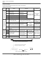
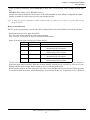
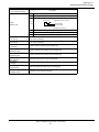
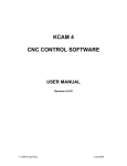
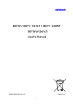
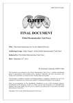
Checking the Nameplate
Inverter
Model
Input Spec.
Output Spec.
Lot No.
Serial No.
UL File No.
CIMR-P543P7
SPEC : 43P71F_
380-440V
50Hz
AC 3PH
10.2A
INPUT :
380-460V 60Hz
OUTPUT : AC 3PH 0-460V 6.1kVA 8.5A
LOT NO :
MASS : 4.5 kg
SER NO :
Mg
UL FILE NO : E131457
MODEL :
Inverter
Spec.
Mass
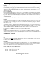
Figure 1 Nameplate Example of American Model CIMR-P543P7
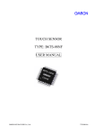
CIMR - P5 4 3P7 1 F
Inverter
P5 Series
Revision symbol
Voltage Class
2: 3-phase, 230V
4: 3-phase, 460V
5: 3-phase, 600V
Enclosure
0: Open chassis
1: NEMA 1 (IP20)
Model Designation
3P7 to 300
See Specifications, pp 6-7
Figure 2 Nameplate Description
IDM P5+ Installation & Quick Start User’s Manual
8
Chapter 1 - Rece v ng & Installat on
Preliminary Inspection
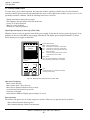
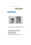
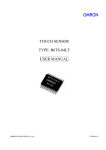
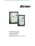
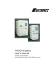
Identifying the Parts
Protective Cover (top/bottom)
4 Mounting Holes
Digital Operator
JVOP-130P
DRIV E FWD
REV
Heatsink
Front Cover
0P
Nameplate
Ventilation Slots
Figure 3 Parts Identification - Model P5U43P7
IDM P5+ Installation & Quick Start User’s Manual
9
Chapter 1 - Rece v ng & Installat on
Mounting
1.4 MOUNTING
!
CAUTION
PRECAUTIONS
1) When preparing to mount the P5+, lift it by its base. Never lift it by the front cover.
2) Mount the inverter onto nonflammable material.
3) The P5+ generates heat. For the most effective cooling possible, mount it vertically. For more details, refer to
“Dimensions/Heat Loss” on pages 12 & 13 and “Clearances” on page 14.
4) When mounting units in an enclosure, install a fan or other cooling device to keep the intake air temperature below
113°F (45°C).
Failure to observe these precautions may result in equipment damage.
Choosing a Location
Be sure that the inverter is mounted in a location protected against the following conditions:
·
·
·
·
·
·
·
·
·
·
·
·
Extreme cold and heat. Use only within the ambient temperature range: 14 to 104°F (-10 to 40°C).
Direct sunlight (not for use outdoors)
Rain, moisture
High humidity
Oil sprays, splashes
Salt spray
Dust or metallic particles in the air
Corrosive gases (e.g. sulfurized gas) or liquids
Radioactive substances
Combustibles (e.g. thinner, solvents, etc.)
Physical shock, vibration
Magnetic noise (e.g. welding machines, power devices, etc.)
IDM P5+ Installation & Quick Start User’s Manual
10
Chapter 1 - Rece v ng & Installat on
Mounting
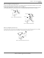
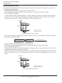
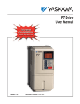
Removing and Replacing the Digital Operator
To remove the digital operator from the front cover, push the operator lever in the direction shown by arrow 1 and lift
the digital operator in the direction shown by arrow 2 (see Figure 4).
To replace the digital operator, engage the operator onto retaining tabs A in the direction shown by arrow 1 and then
onto retaining tabs B in the direction shown by arrow 2, locking the digital operator into place (see Figure 5).
2
Front Cover
Digital Operator
1
Digital Operator
2
1
Front Cover
Figure 4 Removing the Digital Operator
Retaining
Tabs A
Retaining
Tabs B
Figure 5 Replacing the Digital Operator
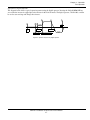
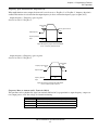
Removing and Replacing the Front Cover
To remove the front cover, first remove the digital operator (see previous section). Then squeeze the cover on both
sides in the direction shown by arrows 2 and lift the cover in the direction shown by arrow 3.
1
Front Cover
2
3
2
Figure 6 Removing and Replacing the Front Cover
IDM P5+ Installation & Quick Start User’s Manual
11
Chapter 1 - Rece v ng & Installat on
Mounting
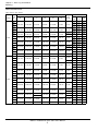
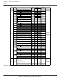
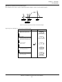
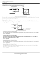
Dimensions/Heat Loss
Open Chassis Type (IP00)
Voltage
230V
Model
P5U20P4
20P7
21P5
22P2
23P7
25P5
27P5
2011
2015
2018
2022
2030
2037
2045
2055
460V
2075
40P4
40P7
41P5
42P2
43P7
44P0
45P5
47P5
4011
4015
4018
4022
4030
4037
4045
4055
4075
4110
4160
4185
4220
4300
Open Chassis Dimensions in inches (mm)
W
H
D
W1
H1
H2
Mass
lbs (kg)
5.51 (140)
11.02 (280)
6.30 (160)
4.96 (126)
10.47 (266)
0.28 (7)
6.5 (3)
5.51 (140)
11.02 (280)
7.09 (180)
4.96 (126)
10.47 (266)
0.28 (7)
10 (4.5)
7.87 (200)
11.81 (300)
8.07 (205)
7.32 (186)
11.22 (285)
0.31 (8)
12 (5.5)
13 (6)
9.84 (250)
14.96 (380)
8.86 (225)
9.29 (236)
14.37 (365)
0.30 (7.5)
24 (11)
12.80 (325)
17.72 (450)
11.22 (285)
10.83 (275)
17.13 (435)
0.30 (7.5)
62 (28)
16.73 (425)
26.57 (675)
13.78 (350)
12.60 (320)
25.59 (650)
0.49 (12.5)
134 (61)
137 (62)
18.70 (475)
31.50 (800)
13.78 (350)
14.57 (370)
30.51 (775)
0.49 (12.5)
176 (80)
22.64 (575)
36.42 (925)
15.75 (400)
17.52 (445)
35.24 (895)
0.59 (15)
298 (135)
5.51 (140)
11.02 (280)
6.30 (160)
4.96 (126)
10.47 (266)
0.28 (7)
6.5 (3)
8.8 (4)
5.51 (140)
11.02 (280)
7.09 (180)
4.96 (126)
10.47 (266)
0.28 (7)
10 (4.5)
7.87 (200)
11.81 (300)
8.07 (205)
7.32 (186)
11.22 (285)
0.31 (8)
13 (6)
9.84 (250)
14.96 (380)
8.86 (225)
9.29 (236)
14.37 (365)
0.30 (7.5)
24 (11)
12.80 (325)
17.72 (450)
11.22 (285)
10.83 (275)
17.13 (435)
0.30 (7.5)
60 (27)
12.80 (325)
24.61 (625)
11.22 (285)
10.83 (275)
24.02 (610)
0.30 (7.5)
97 (44)
17.91 (455)
32.28 (820)
13.78 (350)
13.78 (350)
31.30 (795)
0.49 (12.5)
174 (79)
176 (80)
22.64 (575)
36.42 (925)
14.76 (375)
15.75 (400)
17.52 (445)
35.24 (895)
0.59 (15)
298 (135)
320 (145)
37.40 (950)
57.09 (1450)
17.13 (435)
29.53 (750)
55.12 (1400)
0.98 (25)
794 (360)
37.80 (960)
62.99 (1600)
17.91 (455)
29.53 (750)
61.02 (1550)
0.98 (25)
926 (420)
IDM P5+ Installation & Quick Start User’s Manual
12
Heat
sink
Heat Loss (W)
Inside
Total
unit
15
25
40
80
135
210
235
50
65
80
60
80
90
110
65
90
120
140
215
300
345
425
525
655
830
1050
1250
160
200
230
280
500
700
585
725
885
1110
1550
1950
1550
1950
2300
10
20
30
65
80
120
135
240
305
390
465
620
705
875
970
1110
1430
750
1000
1300
50
65
80
60
65
80
85
120
150
180
195
260
315
370
415
710
890
2300
2950
3600
60
85
110
125
145
200
220
360
455
570
660
880
1020
1245
1385
1820
2320
1870
2670
3400
4740
6820
1160
1520
1510
2110
2910
3030
4190
4910
6850
9730
Chapter 1 - Rece v ng & Installat on
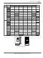
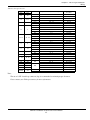
Mounting
Enclosed Type (NEMA 1, IP20)
2030
2037
2045
2055
2075
40P4
40P7
41P5
42P2
43P7
44P0
45P5
47P5
4011
4015
4018
4022
4030
4037
4045
4055
4075
4110
4160
H1
H2
Mass
lbs (kg)
4.96 (126)
10.47 (266)
0.28 (7)
6.5 (3)
7.09 (180)
4.96 (126)
10.47 (266)
0.28 (7)
10 (4.5)
8.07 (205)
7.32 (186)
11.22 (285)
0.31 (8)
12 (5.5)
13 (6)
8.86 (225)
9.29 (236)
14.37 (365)
11.22 (285)
10.83 (275)
17.13 (435)
H
5.51 (140)
11.02 (280)
6.30 (160)
5.51 (140)
11.02 (280)
7.87 (200)
11.81 (300)
9.84 (250)
12.99 (330)
14.96 (380)
15.75 (400)
24.02 (610)
26.57 (675)
0.30 (7.5)
1.08 (27.5)
3.44 (87.5)
6.00 (152.5)
24 (11)
71 (32)
16.93 (430)
38.78 (985)
13.78 (350)
12.60 (320)
25.59 (650)
8.37 (212.5)
148 (67)
150 (68)
18.90 (480)
43.70 (1110)
13.78 (350)
14.57 (370)
30.51 (775)
8.37 (212.5)
192 (87)
22.83 (580)
50.79 (1290)
15.75 (400)
17.52 (445)
35.24 (895)
10.63 (270)
320 (145)
5.51 (140)
11.02 (280)
6.30 (160)
4.96 (126)
10.47 (266)
0.28 (7)
5.51 (140)
11.02 (280)
7.09 (180)
4.96 (126)
10.47 (266)
0.28 (7)
10 (4.5)
7.87 (200)
11.81 (300)
8.07 (205)
7.32 (186)
11.22 (285)
0.31 (8)
13 (6)
9.84 (250)
14.96 (380)
8.86 (225)
9.29 (236)
14.37 (365)
0.30 (7.5)
24 (11)
12.99 (330)
24.02 (610)
11.22 (285)
10.83 (275)
17.13 (435)
3.44 (87.5)
68 (31)
11.22 (285)
10.83 (275)
24.02 (610)
12.99 (330)
30.91 (785)
33.46 (850)
3.44 (87.5)
6.00 (152.5)
6.5 (3)
8.8 (4)
106 (48)
18.11 (460)
44.49 (1130)
13.78 (350)
13.78 (350)
31.30 (795)
8.37 (212.5)
187 (85)
190 (86)
22.83 (580)
50.79 (1290)
14.76 (375)
15.75 (400)
17.52 (445)
35.24 (895)
10.63 (270)
320 (145)
342 (155)
W1
W
H
460V
25P5
27P5
2011
2015
2018
2022
NEMA 1 Dimensions in inches (mm)
D
W1
W
H1
230V
Model
P5U20P4
20P7
21P5
22P2
23P7
H2
Voltage
Front View
D
Side View
Figure 7 P5+ Dimension Diagram
IDM P5+ Installation & Quick Start User’s Manual
13
Chapter 1 - Rece v ng & Installat on
Mounting
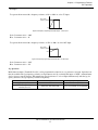
Clearances
When mounting the P5+, allow sufficient clearances for effective cooling as shown below:
1.97in (50mm)
Air
4.72in (120mm)
1.18in (30mm)
1.97in (50mm)
4.72in (120mm)
Air
Front View
Side View
Figure 8 P5+ Clearances
Notes:
1) The required clearances at the top, bottom, and both sides of the inverter are the same for both open chassis
and NEMA 1 enclosures.
2) For inverter models 25HP and less (230V & 460V), remove the top and bottom covers to convert NEMA 1
units to open chassis
3) Allowable intake air temperature:
Open chassis:
14°F to 113°F (-10°C to +45°C)
NEMA 1:
14°F to 104°F (-10°C to 40°C)
4) When mounting units in an enclosure, install a fan or other cooling device to limit the air temperature within
the inverter to below 113°F (45°C).
IDM P5+ Installation & Quick Start User’s Manual
14
Chapter 1 - Rece v ng & Installat on
Wiring
1.5 WIRING
!
CAUTION
PRECAUTIONS
1) Do not connect or disconnect wiring, or perform signal checks while the power supply is turned ON.
2) Connect the power supply wiring to terminals L1, L2 and L3 on the main circuit input section. DO NOT connect the
power supply wiring to output terminals T1, T2 and T3.
3) Connect the motor wiring to terminals T1, T2 and T3 on the main circuit output section.
4) Never touch the output circuit directly or place the output line in contact with the inverter enclosure.
5) Do not connect a phase-advancing capacitor or an LC/RC noise filter to the output circuit.
6) The motor wiring must be less than 328ft (100m) in length and in a separate conduit from the input power wiring.
7) Control wiring must be less than 164ft (50m) in length and in a separate conduit from both the motor wiring and the
power wiring.
8) Tighten the screws on the main circuit and control circuit terminals.
9) Low voltage wires shall be wired with Class 1 wiring.
10)Please observe national electrical code (NEC) when wiring electrical devices.
Failure to observe these precautions may result in equipment damage.
Inspection
After wiring is complete, verify that:
All wiring is correctly installed.
Excess screws and wire clippings are removed from inside of the unit.
Screws are securely tightened.
Exposed wire has no contact with other wiring or terminals.
IDM P5+ Installation & Quick Start User’s Manual
15
Chapter 1 - Rece v ng & Installat on
Wiring
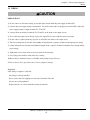
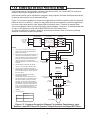
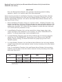
P5+ Standard Connection Diagram
DC Link Reactor (option)
B1 B2
⊕1
⊕2
L1
T1
L2
T2
L3
T3
Ground
230V units: 100Ω or less
460V units: 10Ω or less
IM
Gate Drive
S1 - Fixed
S2
S3
S4
Multi-Function
Contact Inputs
PWM
8 bit
S5
S6
0~10V
AM
Multi-Function
Analog Outputs
(Com) AC
SC (Com)
G
G
FS (+15V)
Analog Inputs
Input FI selectable
4~20mA
or
0~10V
0~+10V
FV (20kΩ)
4~20mA
FI (250Ω)
Serial Port
MA
A/D
10 bit
FC (0V)
RS-232
(10-pin)
MB
MC
M1
M2
Multi-Function
Contact Outputs
250VAC, 1A or less
30VDC, 1A or less
Digital
Operator
Figure 9 P5+ Terminal Diagram
230V: Models 20P4 through 27P5
460V: Models 40P4 through 4015
IDM P5+ Installation & Quick Start User’s Manual
16
Chapter 1 - Rece v ng & Installat on
Wiring
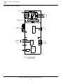
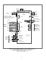
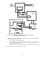
P5+ Standard Connection Diagram
T1
L1
L2
L3
T2
IM
T3
L11
L21
L31
Ground
230V units: 100Ω or less
460V units: 10Ω or less
Gate Drive
S1 - Fixed
S2
S3
S4
Multi-Function
Inputs
PWM
8 bit
S5
S6
0~10V
AM
Multi-Function
Analog Outputs
(Com) AC
SC (Com)
G
G
FS (+15V)
Analog Inputs
Input FI selectable
4~20mA
or
0~10V
0~+10V
FV (20kΩ)
4~20mA
FI (250Ω)
Serial Port
MA
A/D
10 bit
FC (0V)
RS-232
(10-pin)
MB
MC
M1
M2
Multi-Function
Relay Outputs
250VAC, 1A or less
30VDC, 1A or less
Digital
Operator
Figure 10 P5+ Terminal Diagram
230V: Models 2018 through 2075
460V: Models 4018 through 4160
IDM P5+ Installation & Quick Start User’s Manual
17
Chapter 1 - Rece v ng & Installat on
Wiring
Main Circuit Wiring
Input Wiring
· Molded-Case Circuit Breaker (MCCB)
Be sure to connect MCCBs or fuses between the AC main circuit power supply and P5+ input terminals L1, L2 and
L3, to protect the power supply wiring.
· Ground Fault Interrupter
When connecting a ground fault interrupter to input terminals L1, L2 and L3, select one that is not affected by high
frequency.
Examples:
NV series by Mitsubishi Electric Co., Ltd. (manufactured in or after 1988),
EGSG series by Fuji Electric Co., Ltd. (manufactured in or after 1984).
· Magnetic Contactor (MC)
Inverters can be used without an MC installed on the power supply side. An MC can be used instead of an MCCB to
apply the main circuit power supply. However, when an MC is switched OFF on the primary side, dynamic braking
does not function and the motor coasts to stop.
The load can be operated/stopped by closing/opening the MC on the primary side. However, frequent switching may
cause the inverter to malfunction.
When using a braking resistor unit, use an MC to break the power supply side of the inverter in the event of a dynamic
braking overload relay trip. Otherwise, if the inverter malfunctions, the braking resistor unit may be burned out.
· Terminal Block Connection Sequence
Input power supply phases can be connected to any terminal regardless of the order of L1, L2 and L3 on the terminal
block.
· AC Reactor
When connecting an inverter (230V/460V, 25HP or less) to a large capacity power supply transformer (600kVA or
more), or when switching a phase-advancing capacitor, excessive peak current flows through the input power supply circuit, which may damage the converter section. In such cases, install a DC reactor (optional) between inverter ⊕1 and ⊕2
terminals, or an AC reactor (optional) on the input side. Installation of a reactor is also effective for improving power factor on the power supply side.
· Surge Suppressor
For inductive loads (i.e. magnetic contactors, magnetic relays, magnetic valves, solenoids, magnetic brakes, etc.)
connected near the inverter, use a surge suppressor across the coils to limit the transients on the supply lines.
IDM P5+ Installation & Quick Start User’s Manual
18
Chapter 1 - Rece v ng & Installat on
Wiring
Output Wiring
· Motor Connection
Connect motor lead wires to output terminals T1, T2 and T3. Verify that the motor rotates in the forward direction
(CCW: counterclockwise when viewed from the motor load side) with the forward run command. If the motor rotation is incorrect, exchange any two of the motor leads.
· Magnetic Starter
Do not connect a magnetic starter or a magnetic contactor to the output circuit. If the motor load is connected or disconnected while the inverter is running, the inverter overcurrent protective circuitry may trip.
· Thermal Overload Relay
An electronic overload protective function (I2t) is incorporated into the inverter. However, when driving several
motors with one inverter, or when switching between multiple windings of a multiple winding motor, use an external
thermal overload relay(s). In this case, set parameter n034 to “Disabled”.
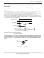
· Wiring Distance Between Inverter and Motor
If the total wiring distance between inverter and motor is excessively long and the inverter carrier frequency (IGBT
switching frequency) is high, harmonic leakage current from the wiring will adversely affect the inverter and peripheral devices. If the wiring distance is long, reduce the inverter carrier frequency as described below. Carrier frequency can be set by parameter n054.
Wiring Distance Between Inverter and Motor
Wiring Distance between
Inverter and Motor
Carrier Frequency *
(Set value of parameter n054)
Up to 164 ft.
(50m)
15kHz or less
(6)
Up to 328 ft.
(100m)
10kHz or less
(4)
More than 328 ft.
(100m)
5kHz or less
(2)
* Increasing the carrier frequency above the factory default value requires current derating. Contact your IDM representative for details.
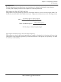
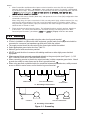
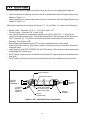
Grounding
· Ground Resistance
230V class: 100Ω or less, 460V class: 10Ω or less.
· Never ground the P5+ in common with welding machines, motors, or other high-current electrical equipment. Run all
ground wiring in a separate conduit.
· Use ground wiring as specified in “Wire and Terminal Screw Sizes” on page 21, and keep the length as short as possible.
· When using several P5+ units side by side, ground the units as shown in Figure 11, (a) or (b). Do not loop the wires
as shown in (c).
(a) Acceptable
(b) Acceptable
(c) Not Acceptable
Figure 11 Grounding Example of 3 P5+ Inverters
IDM P5+ Installation & Quick Start User’s Manual
19
Chapter 1 - Rece v ng & Installat on
Wiring
Terminal Functions
230V Class Terminal Functions
Model P5UNominal Motor Output
L1
L2
L3
L11
L21
L31
T1
T2
T3
B1
B2
⊕1
⊕2
⊕3
20P4 to 27P5
0.5 to 10HP
2011 to 2015
20 to 25HP
2018 to 2075
30 to 125HP
Main circuit input power supply
Main circuit input
power supply
---
Inverter output
Braking resistor unit
DC reactor (⊕1 - ⊕2)
DC power supply (⊕1 - )
---
--DC reactor (⊕1 - ⊕2)
DC power supply (⊕1 - )
Braking unit (⊕3 - )
---
Ground terminal (Ground resistance: 100Ω or less)
460V Class Terminal Functions
Model P5UNominal Motor Output
L1
L2
L3
L11
L21
L31
T1
T2
T3
B1
B2
⊕1
⊕2
r
s 200
s 400
40P4 to 4015
0.5 to 25HP
4018 to 4045
30 to 75HP
4055 to 4160
100 to 250HP
4185 to 4300
300 to 500HP
Main circuit input
power supply
Main circuit input
power supply
Main circuit input power supply
---
---
Inverter output
Braking resistor unit
---
DC reactor (⊕1 - ⊕2)
DC power supply (⊕1 - )
---
Cooling fan power supply
(Control power supply)
--r - s 200: 200 to 230 VAC input
r - s 400: 380 to 460 VAC input
Ground terminal (Ground resistance: 10Ω or less)
IDM P5+ Installation & Quick Start User’s Manual
20
Chapter 1 - Rece v ng & Installat on
Wiring
Wire and Terminal Screw Sizes
230V Class Wire Size
Circuit
Model
P5U20P4
P5U20P7
P5U21P5
P5U22P2
P5U23P7
P5U25P5
P5U27P5
P5U2011
Main
P5U2015
P5U2018
P5U2022
P5U2030
P5U2037
P5U2045
P5U2055
P5U2075
Control
Terminal Symbol
L1, L2, L3,
, ⊕1, ⊕2, B1, B2, T1, T2, T3
L1, L2, L3,
, ⊕1, ⊕2, B1, B2, T1, T2, T3
L1, L2, L3,
, ⊕1, ⊕2, B1, B2, T1, T2, T3
L1, L2, L3,
, ⊕1, ⊕2, B1, B2, T1, T2, T3
L1, L2, L3,
, ⊕1, ⊕2, B1, B2, T1, T2, T3
L1, L2, L3,
, ⊕1, ⊕2, B1, B2, T1, T2, T3
L1, L2, L3,
, ⊕1, ⊕2, B1, B2, T1, T2, T3
L1, L2, L3,
, ⊕1, ⊕2, ⊕3, T1, T2, T3
L1, L2, L3,
, ⊕1, ⊕2, ⊕3, T1, T2, T3
L1, L2, L3, L11, L21, L31, T1, T2, T3
L1, L2, L3, L11, L21, L31, T1, T2, T3
L1, L2, L3, L11, L21, L31, T1, T2, T3
L1, L2, L3, L11, L21, L31, T1, T2, T3
L1, L2, L3, L11, L21, L31, T1, T2, T3
L1, L2, L3, L11, L21, L31, T1, T2, T3
L1, L2, L3, L11, L21, L31, T1, T2, T3
S1, S2, S3, S4, S5, S6, SC
Common to all FV, FI, FS, FC
AM, AC, M1, M2, MA, MB, MC
models
G
Terminal
Screw
Wire Size *
AWG
mm2
Max. Torque
lb-in (N·m)
M4
14 - 10
2 - 5.5
12.4 (1.4)
M4
14 - 10
2 - 5.5
12.4 (1.4)
M4
14 - 10
12 - 10
2 - 5.5
3.5 - 5.5
12.4 (1.4)
M4
12 - 10
3.5 - 5.5
12.4 (1.4)
M4
10
5.5
12.4 (1.4)
M10
M8
M10
M8
M10
M8
M10
M8
M12
M8
8
10 - 8
8
10 - 8
4
8
3
8
3
6
2
6
4/0
4
1/0 x 2P
4
1/0 x 2P
4
1/0 x 2P
3
4/0 x 2P
1
8
5.5 - 8
8
5.5 - 8
22
8
30
8
30
14
38
14
100
22
60 x 2P
22
60 x 2P
22
60 x 2P
30
100 x 2P
50
Stranded
0.5 - 1.25
-
20 - 16
M5
M5
M6
M8
M6
M8
M8
M3.5
20 - 14
22.1 (2.5)
22.1 (2.5)
45.1 (5.1)
90.3 (10.2)
45.1 (5.1)
Power cable:
600V vinyl
sheathed wire or
equivalent
90.3 (10.2)
90.3 (10.2)
203.6 (23.0)
90.3 (10.2)
203.6 (23.0)
90.3 (10.2)
203.6 (23.0)
90.3 (10.2)
203.6 (23.0)
90.3 (10.2)
349.6 (39.5)
90.3 (10.2)
Solid
0.5 - 1.25
0.5 - 2
Wire Type
Twisted
shielded wire with
Class 1 wiring
8.9 (1.0)
* Wire sizes are based on 75°C copper wire.
Note:
Voltage drop should be considered when determining wire size. Voltage drop can be calculated using the following
equation:
Phase-to phase voltage drop (V) = √ 3 wire resistance (Ω/km) x wiring distance (m) x current (A) x 10-3
Select a wire size so that voltage drop will be less than 2% of the normal rated voltage.
IDM P5+ Installation & Quick Start User’s Manual
21
Chapter 1 - Rece v ng & Installat on
Wiring
460V Class Wire Size
Circuit
Model
P5U40P4
P5U40P7
P5U41P5
P5U42P2
P5U43P7
P5U45P5
P5U47P5
P5U4011
P5U4015
P5U4018
P5U4022
P5U4030
Main
P5U4037
P5U4045
P5U4055
P5U4075
P5U4110
P5U4160
Terminal Symbol
L1, L2, L3,
, ⊕1, ⊕2, B1, B2, T1, T2, T3
L1, L2, L3,
, ⊕1, ⊕2, B1, B2, T1, T2, T3
L1, L2, L3,
, ⊕1, ⊕2, B1, B2, T1, T2, T3
L1, L2, L3,
, ⊕1, ⊕2, B1, B2, T1, T2, T3
L1, L2, L3,
, ⊕1, ⊕2, B1, B2, T1, T2, T3
L1, L2, L3,
, ⊕1, ⊕2, B1, B2, T1, T2, T3
L1, L2, L3,
, ⊕1, ⊕2, B1, B2, T1, T2, T3
L1, L2, L3,
, ⊕1, ⊕2, B1, B2, T1, T2, T3
L1, L2, L3,
, ⊕1, ⊕2, B1, B2, T1, T2, T3
L1, L2, L3, L11, L21, L31, T1, T2, T3
L1, L2, L3, L11, L21, L31, T1, T2, T3
L1, L2, L3, L11, L21, L31, T1, T2, T3
L1, L2, L3, L11, L21, L31, T1, T2, T3
L1, L2, L3, L11, L21, L31, T1, T2, T3
L1, L2, L3, L11, L21, L31, T1, T2, T3
L1, L2, L3, L11, L21, L31, T1, T2, T3
L1, L2, L3, L11, L21, L31, T1, T2, T3
L1, L2, L3, L11, L21, L31, T1, T2, T3
L1, L2, L3,
, ⊕1, ⊕3, T1, T2, T3
P5U4185
r, s200, s400
L1, L2, L3, , ⊕1, ⊕3, T1, T2, T3
P5U4220
r, s200, s400
L1, L2, L3, , ⊕1, ⊕3, T1, T2, T3
P5U4300
r, s200, s400
S1, S2, S3, S4, S5, S6, SC
Common to
FV, FI, FS, FC
Control
all
AM, AC, M1, M2, MA, MB, MC
models
G
Terminal
Screw
M4
Wire Size *
AWG
mm2
Max. Torque
lb-in (N·m)
14 - 10
2 - 5.5
14 - 10
12 - 10
14 - 10
12 - 10
14 - 10
12 - 10
14 - 10
12 - 10
2 - 5.5
3.5 - 5.5
2 - 5.5
3.5 - 5.5
2 - 5.5
3.5 - 5.5
2 - 5.5
3.5 - 5.5
M4
12 - 10
3.5 - 5.5
12.4 (1.4)
M5
8-6
8 - 14
22.1 (2.5)
M5
M6
M5
M6
M6
M8
M6
M8
8 - 14
8 - 14
8 - 14
8 - 14
14
8 - 14
22
22
22
22
30
22
50
30
100
50
60 x 2P
60
60 x 2P
60
100 x 2P
100
22.1 (2.5)
45.1 (5.1)
22.1 (2.5)
45.1 (5.1)
45.1 (5.1)
90.3 (10.2)
45.1 (5.1)
90.3 (10.2)
203.6 (23.0)
90.3 (10.2)
203.6 (23.0)
90.3 (10.2)
203.6 (23.0)
90.3 (10.2)
349.6 (39.5)
90.3 (10.2)
325 x 2P
867.4 (98.0)
325
0.5 - 5.5
90.3 (10.2)
12.4 (1.4)
325 x 2P
867.4 (98.0)
325
0.5 - 5.5
90.3 (10.2)
12.4 (1.4)
325 x 2P
867.4 (98.0)
M8
M4
8-6
8-6
8-6
8-6
6
8-6
4
4
4
4
3
4
1
3
4/0
1
1/0 x 2P
1/0
1/0 x 2P
1/0
4/0 x 2P
4/0
650MCM
x 2P
650MCM
20 - 10
650MCM
x 2P
650MCM
20 - 10
650MCM
x 2P
650MCM
20 - 10
90.3 (10.2)
12.4 (1.4)
-
20 - 16
325
0.5 - 5.5
Stranded
0.5 - 1.25
M4
M4
M4
M4
M8
M8
M8
M10
M8
M10
M8
M10
M8
M12
M8
M16
M8
M4
M16
M8
M4
M16
M3.5
Solid
0.5 - 1.25
20 - 14
0.5 - 2
* Wire sizes are based on 75°C copper wire.
IDM P5+ Installation & Quick Start User’s Manual
22
Wire Type
12.4 (1.4)
12.4 (1.4)
12.4 (1.4)
12.4 (1.4)
12.4 (1.4)
90.3 (10.2)
90.3 (10.2)
90.3 (10.2)
-
8.9 (1.0)
Power cable:
600V vinyl
sheathed wire
or equivalent
Twisted shielded wire with
Class 1 wiring
Chapter 1 - Rece v ng & Installat on
Wiring
JST Closed Loop Connectors
Wire Size *
AWG
mm2
20
0.5
18
0.75
16
1.25
14
2
12 - 10
3.5 - 5.5
8
8
6
14
4
22
3-2
30 - 38
1 - 1/0
50 - 60
3/0
4/0
4/0
300MCM
400MCM
80
100
100
150
200
650MCM
325
Terminal Screw
JST Closed-Loop Connectors (Lugs)
M3.5
M4
M3.5
M4
M3.5
M4
M3.5
M4
M5
M6
M8
M4
M5
M6
M8
M5
M6
M8
M6
M8
M6
M8
M8
M8
M10
1.25 - 3.5
1.25 - 4
1.25 - 3.5
1.25 - 4
1.25 - 3.5
1.25 - 4
2 - 3.5
2-4
2-5
2-6
2-8
5.5 - 4
5.5 - 5
5.5 - 6
5.5 - 8
8-5
8-6
8-8
14 - 6
14 - 8
22 - 6
22 - 8
38 - 8
60 - 8
60 - 10
80 - 10
100 - 10
100 - 12
150 - 12
200 - 12
325 - 12
325 - 16
M10
M12
M12 x 2
M16
Max. Torque
lb-in (N·m)
8.9 (1.0)
12.4 (1.4)
8.9 (1.0)
12.4 (1.4)
8.9 (1.0)
12.4 (1.4)
8.9 (1.0)
12.4 (1.4)
22.1 (2.5)
45.1 (5.1)
90.3 (10.2)
12.4 (1.4)
22.1 (2.5)
45.1 (5.1)
90.3 (10.2)
22.1 (2.5)
45.1 (5.1)
90.3 (10.2)
45.1 (5.1)
90.3 (10.2)
45.1 (5.1)
90.3 (10.2)
90.3 (10.2)
90.3 (10.2)
203.6 (23.0)
203.6 (23.0)
203.6 (23.0)
349.6 (39.5)
349.6 (39.5)
349.6 (39.5)
349.6 (39.5)
867.4 (98.0)
Note:
The use of a JST closed-loop connector (lug) is recommended to maintain proper clearances.
Please contact your IDM representative for more information.
IDM P5+ Installation & Quick Start User’s Manual
23
Chapter 1 - Rece v ng & Installat on
Wiring
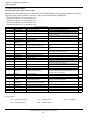
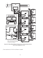
Control Circuit Wiring
The following table outlines the functions of the control circuit terminals.
Control Circuit Terminals
Analog Input Signal
Multi-function Input Signal
ClassificaTerminal
Function
tion
S1
Forward run/stop
Multi-function
Output Signal
Signal Level
Photo-coupler
insulation
Input: +24VDC 8mA
S2
Reverse run/stop
S3
External fault input
S4
S5
S6
SC
Fault reset input
Multi-step speed reference 1
Multi-step speed reference 2
Sequence input common terminal
Forward run when closed, stop when open
Reverse run when closed,
stop when open
Fault when closed, normal
Multi-function contact
state when open
inputs (n036 to n040)
Reset when closed
Enabled when closed
Enabled when closed
—
FS
+15V Power supply output
For analog command +15V power supply
FV
Frequency reference input (voltage)
0 to +10V/100%
FI
Frequency reference input (current) 4 to 20mA/100%
FC
Common terminal
Connection to shield sheath of
signal lead
G
Analog
Output
Signal
Description
M1
M2
MA
MB
MC
n043 = “FV=MSTR”: FV
enabled
n043 = “FI=MSTR”:
FI enabled
+15V
(allowable current
20mA max.)
0 to +10V (20kΩ)
4 to 20mA (250Ω)
0V
—
—
—
During running (N.O. contact)
Closed when running
Multi-function contact
output (n042)
Fault contact output
(N.O./N.C. contact)
Fault when closed between
terminals MA and MC
Fault when open between
terminals MB and MC
Multi-function contact
output (n041)
Dry contact
Contact capacity:
250VAC 1A or less
30VDC 1A or less
0 to +10V/100% frequency
Multi-function analog
monitor 1 (n052)
0 to +10V
2mA or less
AM
Frequency meter output
AC
Common
G
S1 S2 S3 SC SC S4 S5 S6 FV FI FS FC AM AC M1 M2 MA MB MC
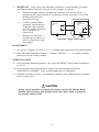
Figure 12 Control Circuit Terminal Arrangement
Insert the wire into the lower part of the terminal
block and connect tightly with a screwdriver.
0.28in (7mm) max
0.02in (0.6mm)
max
0.14in (3.5mm)
max
Figure 13 Wiring the Control Circuit Terminal
IDM P5+ Installation & Quick Start User’s Manual
24
Chapter 2 - Operation
- Chapter 2 -
OPERATION
! WARNING
PRECAUTIONS
1) Only turn ON the input power supply after replacing the front cover. Do not remove the cover while the inverter is
powered up.
2) When the retry function (n060) is selected, do not approach the inverter or the load, since it may restart suddenly
after being stopped.
3) Since the Stop key can be disabled by a function setting, install a separate emergency stop switch to disconnect power
or fault the inverter.
4) Do not touch the heatsink or braking resistor, due to very high temperatures.
5) Since it is very easy to change operation speed from low to high speed, verify the safe working range of the motor
and machine before operation.
6) Install a separate holding brake, if necessary.
7) Do not check signals during operation.
8) All inverter parameters have been preset at the factory. Do not change the settings without thorough review of the
possible consequences.
Failure to observe these precautions may result in equipment damage, serious personal injury, or death.
IDM P5+ Installation & Quick Start User’s Manual
25
Chapter 2 - Operation
Trial Operation
2.1 TRIAL OPERATION
To ensure safety, prior to initial operation, disconnect the machine coupling so that the motor is isolated from the
machine. If initial operation must be performed while the motor is still coupled to the machine, use great care to avoid
potentially hazardous conditions. Check the following items before a trial run:
·
·
·
·
·
Wiring and terminal connections are proper.
Wire clippings and other debris removed from the unit.
Screws are securely tightened.
Motor is securely mounted.
All items are correctly grounded.
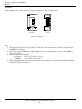
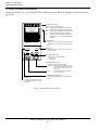
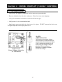
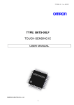
Digital Operator Display at Power-Up (JVOP-130P)
When the system is ready for operation, turn ON the power supply. Verify that the inverter powers up properly. If any
problems are detected, turn OFF the power supply immediately. The digital operator display illuminates as shown
below when the power supply is turned ON.
DRIVE FWD REV
SEQ
REMOTE
REF
Frequency Ref
0.0 HZ
Fref
F/R
Vmtr
FLA
Fout
Montr
V/F
PID
Iout kWout
Accel Decel
Fgain Fbias
kWsav PRGM
DIGITAL OPERATOR
JVOP-130P
DSPL
Operation Mode Indicators:
DRIVE: Lit when in operation mode.
FWD: Lit when there is a forward run command input.
REV: Lit when there is a reverse run command input.
SEQ: Lit when the run command from the control circuit
terminal is enabled.
REF: Lit when the frequency reference from control circuit terminals FV and FI is enabled.
Display Section:
2 line × 16 character alphanumeric LCD that displays
data for monitoring, user parameters, and set values.
ENTER
LOCAL
REMOTE
RUN
STOP
RESET
Keys:
Execute operations such as setting user parameters,
monitoring, and auto-tuning.
Figure 14 Digital Operator Display at Power-up (JVOP-130P)
Operation Checkpoints:
· Motor rotates smoothly.
· Motor rotates in the correct direction.
· Motor has no abnormal vibration and is not noisy.
· Acceleration and deceleration are smooth.
· Unit is not overloaded.
· Status indicator LEDs and digital operator display are correct.
Basic Operation
The inverter will operate after receiving a frequency reference. There are two operation modes for the P5+:
· Run command from the digital operator.
· Run command from the control circuit terminals.
IDM P5+ Installation & Quick Start User’s Manual
26
Chapter 2 - Operation
Trial Operation
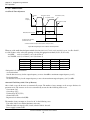
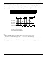
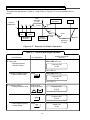
Operation by Digital Operator
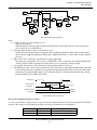
The diagram below shows a typical operation pattern using the digital operator. Pressing the LOCAL/REMOTE key
once while the inverter is stopped places the inverter in the LOCAL mode. The digital operator, JVOP-130P, can then
be used to start and stop and change the reference.
4
1
Power
ON
2
3
5
6
Forward
15Hz
Forward Run
Stop
Reverse Run
Frequency Setting Frequency Reference Change
Reverse
60Hz
Figure 15 Operation Sequence by Digital Operator
IDM P5+ Installation & Quick Start User’s Manual
27
Chapter 2 - Operation
Trial Operation
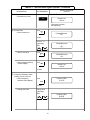
Typical Operation Example by Digital Operator (JVOP-130P)
Description
Key Sequence
(1) Power ON
· Displays frequency reference value.
Operation Condition Setting
· Select LOCAL mode.
(2) Frequency Setting
· Change frequency reference value.
Digital Operator Display
REMOTE LED (SEQ, REF) ON
Frequency Ref
0.0 Hz
LOCAL
REMOTE
Change the value
by depressing
REMOTE LED (SEQ, REF) OFF
Frequency Ref
15.0 Hz
ENTER
Frequency Ref
15.0 Hz
DSPL
Output Freq
0.0 Hz
(3) Forward Run
· Forward run (15Hz)
RUN
Output Freq
15.0 Hz
(4) Frequency Reference Value Change (15~60Hz)
· Select frequency reference value display.
DSPL
· Write-in set value.
· Select output frequency monitor display.
RUN LED ON
Frequency Ref
15.0 Hz
Depress 15 times
· Change set value.
· Write-in set value.
· Select output frequency monitor display.
(5) Reverse Run
· Select reverse run.
Change the value
by depressing
Frequency Ref
60.0 Hz
ENTER
Frequency Ref
60.0 Hz
DSPL
Output Freq
60.0 Hz
DSPL
Forward/Reverse
For
Depress 3 times.
Switch to “rev”
by depressing
Forward/Reverse
rev
REVERSE LED (REV) ON
· Write-in set value.
· Select output frequency monitor display.
ENTER
Forward/Reverse
rev
DSPL
Output Freq
60.0 Hz
Depress 13 times.
(6) Stop
· Decelerates to stop.
STOP
RESET
Output Freq
0.0 Hz
RUN LED OFF STOP LED ON
IDM P5+ Installation & Quick Start User’s Manual
28
Chapter 2 - Operation
Trial Operation
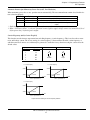
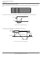
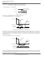
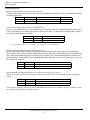
Operation by Control Circuit Terminal Signal
The diagram below shows a typical operation pattern using the control circuit terminal signals.
Forward
60Hz
1
2
3
Operation
Power ON
4
Stop
Frequency Setting
Figure 16 Operation Sequence by Control Circuit Terminal Signal
Typical Operation Example by Control Circuit Terminal Signal
Description
Key Sequence
(1) Power ON
· Displays frequency reference value.
REMOTE mode is preset at the factory.
Digital Operator Display
Frequency Ref
0.0 Hz
REMOTE LED (SEQ, REF) ON
(2) Frequency Setting
· Input frequency reference voltage (current)
by control circuit terminal FV or FI and verify the input value by the digital operator.
Output Frequency Display
· Write-in set value.
(3) Forward Run
· Close between control circuit terminals S1
and SC to perform forward run.
(4) Stop
· Open between control circuit terminals S1
and SC to stop operation.
Frequency Ref
60.0 Hz
For reference voltage 10V
DSPL
Output Freq
0.0 Hz
Output Freq
60.0 Hz
RUN LED ON
Output Freq
0.0 Hz
STOP LED ON
(RUN LED blinking
during deceleration)
IDM P5+ Installation & Quick Start User’s Manual
29
Chapter 2 - Operation
Digital Operator Display
2.2 DIGITAL OPERATOR DISPLAY
All functions of the P5+ are accessed using the JVOP-130P Digital Operator. Below are descriptions of the display and keypad sections.
DRIVE FWD REV
SEQ
REMOTE
REF
Frequency Ref
0.0 HZ
Fref
F/R
Vmtr
FLA
Fout
Montr
V/F
PID
Iout
kWout
Accel Decel
Fgain Fbias
kWsav PRGM
DIGITAL OPERATOR
JVOP-130P
DSPL
Display (LCD)
Displays set values of each function or monitoring values such
as output frequency and current (2 line × 16 character alphanumeric).
ENTER
Enter Key
Displays the current value of each parameter and allows new
values to be entered.
LOCAL
REMOTE
RUN
Operation Mode Indicators:
DRIVE: Lit when in operation mode.
FWD: Lit when there is a forward run command input.
REV: Lit when there is a reverse run command input.
SEQ: Lit when the run command from the control circuit
terminal or serial communication is enabled.
REF: Lit when the frequency reference from control circuit terminals FV or FI, or serial communication is
enabled.
STOP
RESET
Increase/Decrease Keys
Changes set values or parameter numbers.
∧: Increment key
∨: Decrement key
Operation Command Keys
Operation command keys operate the inverter.
STOP/RESET: Red LED lights after depressing STOP key.
Inverter operation is stopped. (resets operation
after faults; reset is disabled while run command is ON)
RUN:
Red LED lights after depressing RUN key.
Inverter operation begins
Operation Mode Selection Key
Display Key
Scrolls through display monitors and QuickStart parameters, and allows access to all
parameters.
Alternate between REMOTE and LOCAL (digital operator)
operation.
Figure 17 Digital Operator Display at Power-up
IDM P5+ Installation & Quick Start User’s Manual
30
Chapter 2 - Operation
LED Description
2.3 LED DESCRIPTION
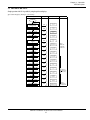
Simple operation of the P5+ is possible, by using the quick-start displays.
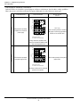
Quick-Start Displays (Example of P5U23P7)
Description
Key Sequence Digital Operator Display
Remarks
Power ON
Frequency reference
setting/monitoring
DSPL
Frequency Ref
0.0 Hz
Output frequency monitor
DSPL
Output Freq
0.0 Hz
Output current monitor
DSPL
Output Amps
0.0 A
Output power monitor
DSPL
Output Power
0.0 kW
FWD/REV run command
selection
DSPL
Monitor selection
DSPL
Acceleration time
DSPL
Accel Time 1
Deceleration time
DSPL
Decel Time 1
Input voltage
DSPL
Input Voltage
V/f pattern selection
DSPL
V/f Selection
Frequency reference gain
DSPL
Terminal FV Gain
Frequency reference bias
DSPL
Terminal FV Bias
Motor rated current
DSPL
Motor rated FLA
PID selection
DSPL
PID Mode
Energy saving selection
DSPL
Energy Sav Sel
Parameter Number/data
DSPL
Forward/Reverse
For
Monitor U-01
Frequency Ref
Depress
[ENTER] key
to display the
monitor value.
10.0 Sec
10.0 Sec
230.0 VAC
60Hz Preset
100%
0%
19.6A
Set/read is
enabled only
during stop.
Disabled
Disabled
Parameter n002
Oper Mode Select
Depress
[ENTER] key
to display data.
IDM P5+ Installation & Quick Start User’s Manual
31
Chapter 2 - Operation
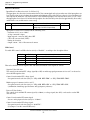
Operation Mode Selection
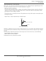
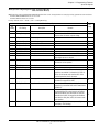
2.4 OPERATION MODE SELECTION (n002, Oper Mode Select)
The P5+ has two operation modes: LOCAL and REMOTE (see table below for description). These two modes can be
selected by the digital operator “LOCAL/REMOTE” key only when operation is stopped. The operation mode selected
can be verified by observing the SEQ and REF LEDs on the digital operator (as shown below). The operation mode is
set to REMOTE (run by control circuit terminals FV and FI frequency reference and run command from control circuit
terminals) prior to shipment. Multi-function contact inputs from control circuit terminals S3 to S6 are enabled in both
operation modes.
· LOCAL:
Both frequency reference and run command are set by the digital operator. Remote SEQ and REF
LEDs go OFF.
· REMOTE: Master frequency reference and run command can be selected as described in the table below.
Parameter n111, LOC/REM Change, will determine if the inverter will acknowledge a previously closed run input during a switchover from LOCAL to REMOTE mode.
· When n111 is set to “Cycle Extern Run”, the inverter will not start if the run input is closed during the transition
from LOCAL to REMOTE.
· When n111 is set to “Acept Extern Run”, the inverter will immediately start if the run input is closed during the
transition from LOCAL to REMOTE.
Operation Mode Selection
LED
Display
0
LCD
Display
SEQ=OPR REF=OPR
1
SEQ=TRM REF=OPR
2
SEQ=OPR REF=TRM
3
SEQ=TRM REF=TRM
4
SEQ=OPR REF=COM
5
SEQ=TRM REF=COM
6
SEQ=COM REF=COM
7
SEQ=COM REF=OPR
8
SEQ=COM REF=TRM
Operation Method Selection
Operation by run command from digital
operator
Operation by run command from control
circuit terminal
Operation by run command from digital
operator
Operation by run command from control
circuit terminal
Operation by run command from digital
operator
Operation by run command from control
circuit terminal
Operation by run command from serial
communication
Operation by run command from serial
communication
Operation by run command from serial
communication
SEQ
LED
OFF
ON
OFF
ON
OFF
ON
ON
ON
ON
Reference Selection
Master frequency reference from digital
operator
Master frequency reference from digital
operator
Master frequency reference from control
circuit terminals FV and FI
Master frequency reference from control
circuit terminals FV and FI
Master frequency reference set by serial
communication
Master frequency reference set by serial
communication
Master frequency reference set by serial
communication
Master frequency reference from digital
operator
Master frequency reference from control
circuit terminals FV and FI
IDM P5+ Installation & Quick Start User’s Manual
32
REF
LED
OFF
OFF
ON
ON
ON
ON
ON
OFF
ON
Chapter 3 - Programming Features
P5+ Parameters
- Chapter 3 -
PROGRAMMING
FEATURES
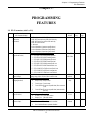
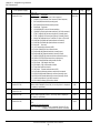
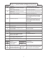
3.1 P5+ Parameters (n001~n116)
No.
Function Name
(LCD Operator Display)
n001 Parameter selection/
initialization
(Password)
n002 Operation mode selection
(Oper Mode Select)
n003 Input voltage
(Input Voltage)
n004 Stopping method
(Stopping Method)
Description
0: n001 read and set, n002~n116 read only
1: n001~n035 read and set, n036~n116 read only
2: n001~n053 read & set, n054~n116 read only
3: n001~n116 read and set
4, 5: Not used
6: 2-wire initialization (Japanese specifications)
7: 3-wire initialization (Japanese specifications)
8: 2-wire initialization (American specifications)
9: 3-wire initialization (American specifications)
LED SettingLCD Setting OperationReference
0 SEQ=OPR REF=OPROperatorOperator
1 SEQ=TRM REF=OPRTerminalOperator
2 SEQ=OPR REF=TRMOperatorTerminal
3 SEQ=TRM REF=TRMTerminalTerminal
4 SEQ=OPR REF=COMOperatorSerial com
5 SEQ=TRM REF=COMTerminalSerial com
6 SEQ=COM REF=COMSerial comSerial com
7 SEQ=COM REF=OPRSerial comOperator
8 SEQ=COM REF=TRMSerial comTerminal
Unit: 0.1V
Setting range: 150.0~255.0V (510V for 460V units)
LED SettingLCD Setting Description
0
Ramp to stop Ramp to stop
1
Coast to stop Coast to stop
2
Coast w/Timer1Coast to stop with timer (Run command
cycle)
User Setting
Ref.
Page
1
43
SEQ=TRM
32
REF=TRM
230.0V
(460.0V)
Ramp to
Stop
59
3
n005 Motor rotation
(Motor Rotation)
n006 Prohibit reverse operation
(Reverse Oper)
Coast w/Timer2Coast to stop with timer (auto-start after
time out)
LED SettingLCD Setting Description
Factory
Default
0
Rotate C.C.W.CCW shaft rotation
1
Rotate C.W. CW shaft rotation
LED SettingLCD Setting Description
0
Rev Allowed Reverse operation enabled
1
Rev ProhibitedReverse operation disabled
IDM P5+ Installation & Quick-start User’s Manual
33
Rotate
C.C.W.
-
Rev
Allowed
57
Chapter 3 - Programm ng Features
P5+ Parameters
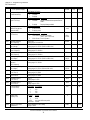
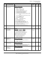
No.
Function Name
(LCD Operator Display)
n007 Local/remote key function
(Local/Remote Key)
n008 Stop key function
(Oper STOP Key)
n009 Frequency reference setting
method from operator
(Operator MOP)
n010 V/f pattern selection
(V/f Selection)
n011 Maximum frequency
(Max Frequency)
n012 Maximum voltage
(Max Voltage)
n013 Base frequency
(Base Frequency)
n014 Mid. output frequency
(Mid Frequency)
n015 Mid. frequency voltage
(Mid Voltage)
n016 Minimum output
frequency
(Min Frequency)
n017 Minimum output voltage
(Min Voltage)
n018 Acceleration time 1
(Accel Time 1)
n019 Deceleration time 1
(Decel Time 1)
n020 Acceleration time 2
(Accel Time 2)
n021 Deceleration time 2
(Decel Time 2)
n022 S-curve selection
(S-Curve Select)
n023 Display mode
(Display Units)
n024 Frequency reference 1
(Reference 1)
Description
LED SettingLCD Setting
0
Disabled
1
Enabled
LED SettingLCD Setting Description
0
Disabled
User Setting
Ref.
Page
Enabled
32
Enabled
-
Enter key
used
-
Stop key is disabled when operated from terminals
1
Enabled
Stop key is always enabled
LED SettingLCD Setting
0
Enter not used
1
Enter key used
LED SettingLCD Setting Description
0
Factory
Default
User Defined V/fCustom V/f pattern
(n011 ~ n017 can be set)
1
60 Hz Preset Fixed V/f pattern
Unit: 0.1Hz
Setting range: 50.0~400.0Hz
Unit: 0.1V
Setting range: 0.1~255.0V (510V for 460V units)
Unit: 0.1Hz
Setting range: 0.2~400.0Hz
Unit: 0.1Hz
Setting range: 0.1~399.9Hz
Unit: 0.1V
Setting range: 0.1~255.0V (510V for 460V units)
Unit: 0.1Hz
Setting range: 0.1~10.0Hz
Unit: 0.1V
Setting range: 0.1~50.0V (510V for 460V units)
Unit: 0.1s (1s for 1000s and above)
Setting range: 0.0~3600s
Unit: 0.1s (1s for 1000s and above)
Setting range: 0.0~3600s
Unit: 1s
Setting range: 0~255s
Unit: 1s
Setting range: 0~255s
LED Setting LCD Setting
0
No S-curve
1
0.2s
2
0.5s
3
1.0s
Setting
Display
0
0.1Hz
1
0.1%
2~39
rpm (input # of motor poles)
40~3999 custom
Setting depends on n023 setting.
Range: 0~9999
IDM P5+ Installation & Quick-start User’s Manual
34
64,81
60 Hz
Preset
60.0Hz
64
230.0V
64
60.0Hz
67
3Hz
64
17.2V
(34.4V)
1.5Hz
64
11.5V
(23.0V)
10.0s
64
44,81
10.0s
44,81
10.0s
44
10.0s
44
0.2s
58
0
-
0.0Hz
55,80
64
Chapter 3 - Programming Features
P5+ Parameters
No.
Function Name
(LCD Operator Display)
n025 Frequency reference 2
(Reference 2)
n026 Frequency reference 3
(Reference 3)
n027 Frequency reference 4
(Reference 4)
n028 Not used
n029 Not used
n030 Jog frequency
(Jog Reference)
n031 Frequency upper limit
(Ref Upper Limit)
n032 Frequency lower limit
(Ref Lower Limit)
n033 Motor rated current
(Motor Rated FLA)
n034 Motor thermal protection
(Motor OL Sel)
n035 Stop method selection -OH1for inverter
overheat pre-alarm
(OH1 Stop Method)
Description
Setting depends on n023 setting.
Range: 0~9999
Setting depends on n023 setting.
Range: 0~9999
Setting depends on n023 setting.
Range: 0~9999
Setting depends on n023 setting.
Range: 0~9999
Unit: 1%
Setting range: 0~109%
Unit: 1%
Setting range: 0~100%
Unit: 0.1A Range: 10~200% inverter rated current
Unit is 1A, when setting is more than 1,000A
LED SettingLCD SettingDescription
0
Disabled
Protection disabled
1
STD Motor/8 minGeneral-purpose motor (time constant 8
min.)
2
STD Motor/5 minGeneral-purpose motor (time constant 5
min.)
3
INV Motor/8 minBlower-cooled motor (time constant 8 min.)
4
INV Motor/ 5 minBlower-cooled motor (time constant 5 min.)
LED SettingLCD Setting Description
0
Ramp STOP/Decel 1Ramp to stop - Decel 1 (fault)
1
Coast to STOPCoast to stop (fault)
2
Ramp STOP/Decel 2Ramp to stop - Decel 2 (fault)
3
Continue OperContinue operation (alarm) at 80% of
frequency reference
IDM P5+ Installation & Quick-start User’s Manual
35
Factory
Default
User Setting
Ref.
Page
0.0Hz
55
0.0Hz
55
0.0Hz
55
6.0Hz
-
51
100%
59
0%
59
kVA dependent
STD Motor/
8 min
53,81
Continue
Oper
-
53
Chapter 3 - Programm ng Features
P5+ Parameters
No.
Function Name
(LCD Operator Display)
n036 Multi-function input selection 1
(Terminal S2 Sel)
n037 Multi-function input 2
(Terminal S3 Sel)
n038 Multi-function input 3
(Terminal S4 Sel)
n039 Multi-function input 4
(Terminal S5 Sel)
n040 Multi-function input 5
(Terminal S6 Sel)
Description
Factory
Default
LED LCD
Reverse
SettingSetting
Description
RUN (2W)
0 Reverse RUN (2W)Reverse run (2-wire sequence)
1 FWD/REV Cmd (3W)Fwd / Rev command (3-wire sequence)
2 Ext Fault (NO)External fault (normally open)
3 Ext Fault (NC)External fault (normally closed)
4 Fault Reset Fault reset
5 LOCAL/REMOTE SelLocal / Remote selection
6 COM/INV SelSerial com/inverter selection (Fref, RUN command)
7 STOP Cmd/Dec2 NOFast stop using Decel 2 (normally open)
8 STOP Cmd/Dec2 NCFast stop using Decel 2 (normally closed)
9 Master Fref SelMaster freq. ref. selection (FV-open or FI-closed)
10 Multi-Step Spd 1Multi-step speed reference command 1
11 Multi-Step Spd 2Multi-step speed reference command 2
12 Not Used Not used
13 JOG CommandJog reference (n030)
14 Acc/Dec SwitchAccel / Decel time selection
15 Ext Baseblk (NO)External baseblock (normally open)
16 Ext Baseblk (NC)External baseblock (normally closed)
17 SpdSrch (MAXFRQ)Speed search from maximum frequency
18 SpdSrch (SETFRQ)Speed search from set frequency
19 Param LockoutParameter setting enable / disable
20 PID I Reset PID integral value reset
21 PID Disable PID control enable / disable
22 Timer Start CmdTimer function
23 OH3 Input External overheat alarm (OH3)
24 Ref Sample HoldAnalog reference sample hold command
25 KEB Cmd (NO)Inertia ridethrough command (normally open)
26 KEB Cmd (NC)Inertia ridethrough command (normally closed)
27 Hold CommandAccel / Decel hold command
28 PID Polarity SelInverse PID enable / disable
Ext Fault
Set items are same as n036.
(NO)
(When n036=”FWD/REV Cmd (3W), “In Use By Other” is displayed,
and setting is prohibited)
Set items are same as n036.
Fault Reset
Set items are same as n036.
(When n040=”Up/Down Control”, “In Use By Other is displayed,
and setting is prohibited)
Set items are same as n036.
LED
SettingLCD SettingDescription
29 Up / Down controlUp / Down command (Terminal S5=Up
command, and terminal S6=Down command).
IDM P5+ Installation & Quick-start User’s Manual
36
User Setting
Ref.
Page
66
66
66
Multi-Step
Spd 1
66
Multi-Step
Spd 2
66
Chapter 3 - Programming Features
P5+ Parameters
No.
Function Name
(LCD Operator Display)
n041 Multi-function output selection
1
(Terminal MA Sel)
Description
LED
SettingLCD SettingDescription
0
1
2
3
4
5
6
7
8
9
10
11
12
13
14
15
16
17
n046 Operation method for
frequency reference
loss detection
(Ref Loss Detect)
User Setting
Ref.
Page
Fault
71
During Running
71
FV=MSTR
70
Fault
Fault
During RunningDuring running
At Speed Frequency agree
At Desired SpeedDesired frequency agree
Freq Detection 1Frequency detection 1
Freq detection 2Frequency detection 2
OverTrq Det (NO)Over/Undertorque detection (normally
open)
OverTrq Det (NC)Over/Undertorque detection (normally
closed)
BaseblockedDuring baseblock
Operation ModeLocal mode
Ready
Inverter operation ready
Timer OutputTimer function
Auto-RestartingDuring auto restart
OL Pre-AlarmOL pre-alarm (80% OL1 or OL2)
Freq Ref LossFrequency reference loss
Set By COM CntlClosed by serial communication
PID Fdbk LossPID feedback loss
OH1 Alarm OH1 Alarm (set if n035 set to "3")
n042 Multi-function output selection Set items are as same as n041
2
(Terminal M1 Sel)
n043 Master analog input selection - LED LCD
SettingSetting
FV
FI
Remarks
FV or FI terminal
(Analog Input Sel)
0 FV=MSTRFI=AUXMasterAux.Enable
1 FV=AUXFI=MSTRAux.MasterEnable
2 FV=RSTFI=MSTRFault resetMasterDisable
Enable:FV/FI switchover function is enabled.
Disable:FV/FI switchover function is disabled.
Note: When PID is enabled (n084 ≠ 0),
FV terminal = PID reference, and
FI terminal = PID feedback.
LED
n044 Aux. analog input
SettingLCD SettingDescription
selection
(Terminal FI Sel)
0 0-10VDC 0~10V input (Jumper J1 must be cut)
n045 Frequency reference retention
(MOP Ref Memory)
Factory
Default
1 4-20mA 4~20mA input
LED
SettingLCD SettingDescription
0 Memorize FrefRetained in frequency reference 1 (n024)
1 Not MemorizedNot retained after power-down
LED
SettingLCD SettingDescription
0
Not detectedNo detection
1
Run @ n047 FrefContinue to run at n047 setting
IDM P5+ Installation & Quick-start User’s Manual
37
FI=AUX
4-20mA
70
Memorize
Fref
70
Not
Detected
70
Chapter 3 - Programm ng Features
P5+ Parameters
No.
Function Name
(LCD Operator Display)
n047 Frequency reference level at
loss of Fref
(Fref Lvl@F Loss)
n048 Terminal FV gain
(Terminal FV Gain)
n049 Terminal FV bias
(Terminal FV Bias)
n050 Terminal FI gain
(Terminal FI Gain)
n051 Terminal FI bias
(Terminal FI Bias)
n052 Multi-function analog
output AM
(Terminal AM Sel)
n053
n054
n055
n056
n057
n058
n059
n060
n061
Description
Unit: 1%
Setting range: 0~100% of setting Fref
Factory
Default
80%
Unit: 1%
100%
Setting range: 0~200%
Unit: 1%
0%
Setting range: -100~100%
Unit: 1%
100%
Setting range: 0~200%
Unit: 1%
0%
Setting range: -100~100%
LED
Output Freq
SettingLCD SettingMonitor
0 Output Freq Output frequency
1 Output AmpsOutput current
2 Output kWattsOutput power
3 DC Bus VoltageDC bus voltage
Analog monitor gain
Unit: 0.01
1.00
(Terminal AM Gain)
Setting range: 0.01~2.00
Carrier frequency
Unit: 1
kVA depen(Carrier Freq Sel)
Setting range: 1~6 (x2.5kHz), 7~9 (custom pattern)
dent
LED LCD
Momentary power loss rideNot
SettingSetting
through method
Provided
Method
(PwrL Selection)
0 Not Provided Not provided
1 2 Seconds MaxContinuous operation after power recovery
within 2s
2 CPU Power ActiveContinuous operation after power recovery within control logic time (no fault output)
110%
Speed search level - decel time Unit: 1% Setting range: 0~200%
100% = inverter rated current
fixed at 2 sec
(SpdSrch Current)
Minimum baseblock time
Unit: 0.1s
kVA
(Min Baseblock t)
Setting range: 0.5~10.0s
dependent
kVA depenV/f reduction level during speed Unit:1%
Setting range: 0~100%
dent
search
(SpdSrch V/f)
Power loss ridethrough time
Unit: 0.1s
kVA depen(PwrL Ridethru t)
Setting range: 0.0~2.0s
dent
Automatic retry attempts
Unit: 1 time
0
(Num of Restarts)
Setting range: 0~10
Fault contact selection during LED
Activate Flt
SettingLCD SettingDescription
automatic retry
Rly
0
Activate Flt RlyClosed during fault retry
(Restart Sel)
1
No Rly OutputOpen during fault retry
n062 Jump frequency 1
(Jump Freq 1)
n063 Jump frequency 2
(Jump Freq 2)
n064 Jump frequency
bandwidth
(Jump Bandwidth)
Unit: 0.1Hz
Setting range: 0.0~400.0Hz
Unit: 0.1Hz
Setting range: 0.0~400.0Hz
Unit: 0.1Hz
Setting range: 0.0~25.5Hz
IDM P5+ Installation & Quick-start User’s Manual
38
User Setting
Ref.
Page
70
50,81
50,81
50
50
49
50
45
45
63
60
-
44
-
0.0Hz
52
0.0Hz
52
1.0Hz
52
Chapter 3 - Programming Features
P5+ Parameters
No.
Function Name
(LCD Operator Display)
Description
LED
SettingLCD SettingDescription
0 Time Power is ONAccumulate time during power on
1 Time Running MtrAccumulate time during running
Elapsed timer 1
Unit: 1 hour
Range: 0~9999
(Elapsed Time 1)
* Initial value becomes 0 only when initialized during CPF4 occurrence.
Elapsed timer 2
Unit: 10,000 hours Range: 0~27
(Elapsed Time 2)
* Initial value becomes 0 only when initialized during CPF4 occurrence.
DC injection current
Unit: 1%
(DCInj Current)
Setting range: 0~100%
100% = inverter rated current
DC injection time at stop
Unit: 0.1s
(DCInj Time @ Stop)
Setting range: 0.0~10.0s
DC injection time at start
Unit: 0.1s
(DCInj Time @ Start)
Setting range: 0.0~10.0s
Torque compensation gain
Unit: 0.1
(Torq Comp Gain)
Setting range: 0.0~3.0
(normally, no adjustment is necessary)
Stall prevention during deceler- LED
SettingLCD Setting
ation
0 Disabled
(StallP Decel Sel)
1 Enabled
Unit: 1% Setting range: 30~200%
Current limit/Stall prevention
When level is set to 200%, current limit during acceleration is dislevel during acceleration
abled.
(StallP Accel Lvl)
Unit: 1% Setting range: 30~200%
Current limit/Stall prevention
When level is set to 200%, current limit during
level during running
running is disabled.
(StallP Run Level)
Frequency agree set point
Unit: 0.1Hz
(Freq Det Level)
Setting range: 0.0~400.0Hz
Frequency agree
Unit: 0.1Hz
detection width
Setting range: 0.0~25.5Hz
(Freq Det Width)
n065 Elapsed timer selection
(Elapsed Timer)
n066
n067
n068
n069
n070
n071
n072
n073
n074
n075
n076
IDM P5+ Installation & Quick-start User’s Manual
39
Factory
Default
User Setting
Ref.
Page
Time
Running Mtr
-
*
-
*
-
50%
47,63
0.0s
47
0.0s
47,63
1.0
61
Enabled
47
kVA
dependent
46
kVA
dependent
46
0.0Hz
49,72
2.0Hz
72
Chapter 3 - Programm ng Features
P5+ Parameters
No.
Description
Factory
Default
n077 Over/Undertorque
detection OL3
(Torq Det Sel)
LED
SettingLCD SettingDescription
0 Disabled Detection disabled
1 OT/Spd Agree/AlmOvertorque detection at speed agree; continue running after detection. (Alarm)
2 OT/Run/AlmOvertorque detection at run; continue running
after detection. (Alarm)
3 OT/Spd Agree/FltOvertorque detection at speed agree; coast
to stop after detection. (Fault)
4 OT/Run/Flt Overtorque detection at run; coasts to stop after
detection. (Fault)
5 UT/Spd Agree/AlmUndertorque detection at speed agree;
continue running after detection. (Alarm)
6 UT/Run/AlmUndertorque detection at run; continue running
after detection. (Alarm)
7 UT/Spd Agree/FltUndertorque detection at speed agree;
coast to stop after detection. (Fault)
8 UT/Run/Flt Undertorque detection at run; coast to stop after
detection. (Fault)
Disabled
62
n078 Over/Undertorque
detection level OL3
(Torq Det Level)
n079 Over/Undertorque detection
delay time OL3
(Torq Det Time)
n080 On-delay timer
(On-Delay Timer)
n081 Off-delay timer
(Off-Delay Timer)
n082 DB resistor overheat
function rH
(DB Resistor Prot)
Unit: 1%
Setting range: 30~200%
100% = inverter rated current
Unit: 0.1s
Setting range: 0.1~10.0s
160%
62
0.1s
62
0.0s
68
0.0s
68
Disabled
-
7%
56
Disabled
56,81
1.00
57
1.0
57
10.0s
57
0.00s
57
n083
n084
n085
n086
n087
n088
Function Name
(LCD Operator Display)
Unit: 0.1s
Setting range: 0.0~25.5s
Unit: 0.1s
Setting range: 0.0~25.5s
LED
SettingLCD SettingDescription
0 DisabledNo DB protection calculated or provided
1 Enabled Protection provided for OMRON
Yaskawa 3% ED resistor
Unit: 1%
Input phase loss
Setting range: 1~100%
detection level SPI
When setting is 100%, this function is disabled.
(In Ph Loss Lvl)
LED
PID selection
SettingLCD SettingDescription
(PID Mode)
0 Disabled PID disabled
1 Enabled D=FdbkPID enabled
2 Enabled D=FdfwdPID w / Feed forward
3 Enabled RevFdbkPID w / Inverted feedback
Feedback calibration gain PID Unit: 0.01
(PID Fdbk Gain)
Setting range: 0.00~10.00
Proportional gain PID
Unit: 0.01
(PID P Gain)
Setting range: 0.0~10.0
Integral time PID
Unit: 0.1s
(PID I Time)
Setting range: 0.0~100.0s
Derivative time PID
Unit: 0.01s
(PID D Time)
Setting range: 0.00~1.00s
IDM P5+ Installation & Quick-start User’s Manual
40
User Setting
Ref.
Page
Chapter 3 - Programming Features
P5+ Parameters
No.
Function Name
(LCD Operator Display)
n089 Limit of integral value PID
(PID I Limit)
n090 Feedback loss detection PID
(PID FdbkLoss Sel)
Description
Unit: 1%
Setting range: 0~109%
LED
SettingLCD Setting
Description
0 Disabled
Detection is disabled.
1 Multi-function Output OnlyDetection is enabled.
Unit: 1%
Setting range: 0~100%
n091 Feedback loss detection level
PID
(PID FdbkLoss Lvl)
n092 Feedback loss detection delay Unit: 0.1s
Setting range: 0.0~25.5s
time PID
(PID FdbkLoss Tim)
LED
n093 PID output selection
Setting
LCD Setting
(PID Output Sel)
0
Not Inverted
1
Inverted
n094 Sleep function start level PID Unit: 0.1Hz
(Sleep Start Lvl)
Setting range: 0.0~400.0Hz
n095 Sleep function delay time PID Unit: 0.1s
(Sleep Delay Time)
Setting range: 0.0~25.5s
LED
n096 Energy saving selection
(Energy Save Sel)
Setting LCD SettingDescription
0
Disabled Energy saving is disabled.
1
Enabled
Energy saving is enabled.
n097 Energy saving gain K2
Unit: 0.01
(Energy Save Gain)
Setting range: 0.00~655.0 (0=No energy saving)
Unit: 1%
n098 Energy saving voltage lower
Setting range: 0~120%
limit at 60Hz
(EngSavVLLmt@60Hz)
n099 Energy saving voltage lower
Unit: 1%
limit at 6Hz
Setting range: 0~25%
(EngSavVLLmt@6Hz)
n100 Time of average kW - Energy Unit: 1 = 25ms
saving
Setting range: 0~200
(EngSavTime/AvgkW)
LED
n101 Modbus time over
detection
Setting LCD SettingDescription
(MODBUS Timeout)
0
DisabledTime Over Detection is disabled.
1
Enabled Time Over Detection is enabled.
n102 MODBUS stop method at com- LED
SettingLCD Setting Stop method
munication error CE
0 Ramp STOP/Decel 1Ramp to stop - Decel 1 (fault)
(MODBUS Fault Stop)
1 Coast to STOPCoast to stop (fault)
2 Ramp STOP/Decel 1Ramp to stop - Decel 2 (fault)
3 Continue OperContinue operation (alarm)
n103 MODBUS frequency reference LED
SettingLCD Setting Stop method
unit
0 1=0.1Hz
0.1Hz / 1
(MODBUS Fref Unit)
1 2=0.01Hz
0.01Hz / 1
2 3000=100% 100% / 30000
3 1=0.1%
0.1% / 1
IDM P5+ Installation & Quick-start User’s Manual
41
Factory
Default
User Setting
Ref.
Page
100%
57
Disabled
-
0%
-
1.0s
-
Not Inverted
-
0.0Hz
57
0.0s
57
Disabled
48,81
kVA dependent
75%
48
48
12%
48
1
-
Enabled
-
Coast to
STOP
-
1=0.1Hz
52
Chapter 3 - Programm ng Features
P5+ Parameters
No.
Function Name
(LCD Operator Display)
n104 MODBUS slave address
(MODBUS Address)
n105 MODBUS BPS selection
(MODBUS Baud Rate)
n106 MODBUS parity selection
(MODBUS Parity)
n107
n108
n109
n110
n111
n112
n113
n114
n115
n116
Slip compensation gain
(Slip Comp Gain)
Motor no-load current
(Mtr No-Load Amp)
Slip compensation primary
delay time constant
(Slip Comp Delay)
Operator connection fault
detection selection
(Oper Detect Flt)
Local / Remote changeover
function selection
(LOC/REM Change)
Description
Unit: 1
Setting range: 0~31
LED
Setting
LCD Setting
0
2400 Baud
1
4800 Baud
2
9600 Baud
LED
Setting
LCD Setting
0
No parity
1
Even parity
2
Odd parity
Unit: 0.1% [of Base Frequency (n013)]
Setting range: 0.0 ~ 9.9%
Unit: 1% [of Motor Rated Current (n033)]
Setting range: 0 ~ 99%
Unit: 0.1s
Setting range: 0.0 ~ 25.5s
LED
Setting
0:
1:
LED
User Setting
Ref.
Page
1
53
9600 Baud
52
No
parity
52
0.0%
65
30%
-
2.0s
65
Disabled
-
Cycle
Extern RUN
32
6.0Hz
-
50%
-
LCD Setting
Disabled
Enabled
Setting
LCD Setting
0
Cycle Extern RUN command
1
Acept Extern RUN command
Low frequency OL start point Unit: 0.1Hz
(Low Freq OL2 Start)
Setting range: 0.0 ~ 10.0Hz
0Hz continuous operation level Unit: 1%
(OL2_Level_@_0 Hz)
Setting range: 25 ~ 100%
Not used
kVA selection
Unit: 1
(Inverter kVA Sel)
Setting range: 0~35
CT / VT selection
(CT / VT Selection)
Factory
Default
LED
SettingLCD SettingDescription
0: CT OperationConstant torque
1: VT OperationVariable torque
IDM P5+ Installation & Quick-start User’s Manual
42
kVA
Dependent
-
-
6,7
Chapter 3 - Programming Features
Parameter Set-up & Initialization
3.2 PARAMETER SET-UP & INITIALIZATION
Parameter Selection/Initialization (n001, Password)
The following table describes data which can be set or read when parameter n001 is set.
Setting
Parameters that can be set
Parameters that can be
viewed
0
(parameter read-only)
1
(factory default)
2
3
4, 5
6
7
8
9
n001
n001 to n116
n001 to n035
n001 to n116
n001 to n053
n001 to n116
n001 to n116
n001 to n116
Not used
Initialize: 2-wire sequence (Japanese specifications)
Initialize: 3-wire sequence (Japanese specifications)
Initialize: 2-wire sequence (American specifications)
Initialize: 3-wire sequence (American specifications)
IDM P5+ Installation & Quick-start User’s Manual
43
Chapter 3 - Programm ng Features
P5+ Operation
3.3 P5+ OPERATION
Accel/Decel Time Adjustment
Decel Time 1 (n019)
Accel Time 1
(n018)
Accel Time 2 (n020)
Output
Frequency
Decel Time 2* (n021)
Decel Time 1* (n019)
Time
FWD (REV) Run Command
ON
OFF
ON
ON
Accel/Decel Time Selection
(Terminals S2 to S6)
* When “deceleration to stop” is selected (n004 = “Ramp to STOP”)
Figure 18 Timing Diagram of Accel/Decel Time Adjustment
When any of the multi-function input terminal selections (n036, n037, n038, n039 or n040) is set to “Acc/Dec Switch”,
accel/decel times can be selected by opening or closing the appropriate terminal (S2, S3, S4, S5 or S6).
At OPEN:
n018 (accel time 1), n019 (decel time 1)
At CLOSED: n020 (accel time 2), n021 (decel time 2)
Parameter No.
n018
n019
n020
n021
Name
Acceleration time 1
Deceleration time 1
Acceleration time 2
Deceleration time 2
Unit
0.1s *
0.1s *
0.1s *
0.1s *
Setting Range Factory Default
0.0 to 3600s
10.0s
0.0 to 3600s
10.0s
0.0 to 3600s
10.0s
0.0 to 3600s
10.0s
* Setting unit is 1s for 1,000s and above.
· Acceleration time
Sets the time necessary for the output frequency to move from 0Hz to maximum output frequency (n011).
· Deceleration time
Set the time necessary for the output frequency to move from maximum output frequency (n011) to 0Hz.
Automatic Fault Retry (n060, Num of Restarts)
After a fault occurs, the inverter can automatically restart. The number of retry attempts can be set up to 10 times via
parameter n060. The inverter can be set to automatically restart after the following faults occur:
· Overcurrent (OC)
· Overvoltage (OV)
· Undervoltage PUV (UV1)
· Ground fault (GF)
· Regenerative transistor fault (RR)
The number of retry attempts are cleared to “0” in the following cases:
· If no other fault occurs within 10 minutes after retry.
· When the fault reset signal is ON (closed) after the fault is detected.
· Power supply is turned OFF.
IDM P5+ Installation & Quick-start User’s Manual
44
Chapter 3 - Programming Features
P5+ Operation
Automatic Restart After Momentary Power Loss (n055, PwrL Selection)
When momentary power loss occurs, operation restarts automatically. The run command must remain closed for this feature to function properly.
LED Setting
0
1*
2 **
LCD Setting
Not Provided
2 Seconds Max
CPU Power Active
Description
Not provided (factory default)
Continuous operation after power recovery within 2 seconds
Continuous operation after power recovery within control logic time (no fault
output)
* Holds the operation signal to continue operation after recovery from momentary power loss.
** When “CPU Power Active” is selected, operation restarts if power supply voltage returns to its normal level (level
before power loss). No fault signal is output.
Carrier Frequency (n054, Carrier Freq Sel)
This function sets the inverter output transistor switching frequency (carrier frequency). This is used to reduce motor
noise and leakage current. The factory setting for carrier frequency is the maximum allowable carrier frequency at
which inverter rated current can continuously be generated. Consult the factory when increasing the carrier above the
default values.
Carrier Frequency (kHz)
LED Setting
Metallic Noise from Motor
Leakage Current
Louder
Smaller
Inaudible
Larger
LCD Setting
1
2
3
4
5
6
2.5
5.0
8.0
10.0
12.5
15.0
fc = carrier frequency
fc = carrier frequency
2.5kHz
1.0kHz
2.5kHz
1.0kHz
fc = 12 fout
83.3Hz
208.3Hz
n054 = “Synchronous 1”
fout
fc = 24 fout
41.6Hz
104.1Hz
n054 = “Synchronous 2”
fc = carrier frequency
2.5kHz
1.0kHz
fc = 36 fout
27.7Hz
69.4Hz
n054 = “Synchronous 3”
fout
Figure 19 Custom Setting of Carrier Frequency Patterns
IDM P5+ Installation & Quick-start User’s Manual
45
fout
Chapter 3 - Programm ng Features
P5+ Operation
Current Limit (Stall Prevention)
This function automatically adjusts the output frequency in response to an increase in load current to continue operation without tripping the inverter.
· Stall Prevention Level During Acceleration (n073, StallP Accel Lvl)
The current limit level during acceleration can be set in units of 1% (inverter rated current = 100%).
Factory setting: kVA dependent
A setting of 200% disables current limit during acceleration. During acceleration, if the output current exceeds the
value set for n073, acceleration stops and frequency is maintained. When the output current goes down below the
value set for parameter n073, acceleration resumes at the normal acceleration rate.
Motor Current
n073
Time
Output Frequency
Time
*
* Holds the output frequency
to limit the load current.
Figure 20 Stall Prevention During Acceleration
In the constant output area [output frequency ≥ base frequency (n013)], the current limit level during acceleration is
changed by the following equation:
Current Limit Level During
Current Limit Level During ×
=
Accel in Constant Output Area
Acceleration (n073)
Base Frequency (n013)
Output Frequency
· Stall Prevention Level During Running (n074, StallP Run Level)
The stall prevention level during running can be set in units of 1% (inverter rated current = 100%).
Factory setting: kVA dependent
A setting of 200% disables current limit during running. During speed agree, if the output current exceeds the value
set for parameter n074, then deceleration is initiated.
While the output current exceeds the value set for n074, deceleration continues. When the output current goes below
the value set for parameter n074, acceleration begins at the normal acceleration rate bringing the motor to the set frequency.
Motor Current
n074
Time
Output Frequency
Time
*
* Decreases the output frequency
to limit the load current.
Figure 21 Stall Prevention During Running
IDM P5+ Installation & Quick-start User’s Manual
46
Chapter 3 - Programming Features
P5+ Operation
· Stall prevention during deceleration (n072, StallP Decel Sel)
To prevent overvoltage during deceleration, the inverter automatically extends the deceleration time according to the
value of main circuit DC voltage. When using an optional braking resistor for the P5+, set parameter n072 to”0”.
LED Setting
0
1
LCD Setting
Disabled
Enabled
Stall Prevention During Deceleration
Disabled (when optional braking resistor mounted)
Enabled (factory default)
Frequency
Extends the deceleration time to
prevent overvoltage fault.
Time
Set Deceleration Time
Figure 22 Stall Prevention During Deceleration
DC Injection Braking
· DC Injection Braking Current (n068, DCInj Current)
DC injection braking current can be set in increments of 1%.
(100% = inverter rated current)
· DC injection Braking Time at Stop (n069, DCInj Time @ Stop)
DC injection braking time at stop can be set in increments of 0.1 second. When parameter n069 is set to “0”, DC
injection braking at stopping is disabled.
n016
Min. Output Frequency
n069
DC injection Braking
Time at Stop
Figure 23a DC Injection Braking Time at Stop
When coast to stop is selected in the stopping method selection (n004), DC injection braking at stop is disabled.
· DC injection Braking Time at Start (n070)
DC injection braking time at start can be set in increments of 0.1 second. When parameter n070 is set to “0”, DC
injection braking at starting is disabled.
n016
Min. Output Frequency
n070
DC injection Braking
Time at Start
Figure 23b DC Injection Braking Time at Start
IDM P5+ Installation & Quick-start User’s Manual
47
Chapter 3 - Programm ng Features
P5+ Operation
Energy Saving Control
To enable energy saving control, set energy saving selection (n096, Energy Sav Sel) to “1”.
LED Setting
0
1
LCD Setting
Disabled
Enabled
Description
Energy saving is disabled (factory default).
Energy saving is enabled.
Since the parameters used in the energy saving control mode have been preset at the factory to the optimum values, it is
not necessary to adjust them under normal operation. If your motor characteristics differ greatly from those of standard
induction motors, refer to the following description to adjust the parameters.
Energy Saving Control Mode
· Energy Saving Gain K2 (n097, Energy Save Gain)
Use this energy saving gain when running in the energy saving control mode to calculate the voltage at which motor
efficiency will be greatest, and set it as the output voltage reference. This value is preset at the factory to the standard
induction motor value prior to shipment. As the energy saving gain increases, output voltage decreases.
· Energy Saving Voltage Lower Limit ( n098, EngSavVLLmt@60Hz; n099, EngSavVLLmt@ 6Hz)
Sets the output voltage lower limit. If the voltage reference value calculated in the energy saving mode is smaller
than the specified lower limit, this lower limit value is output as the voltage reference value. The lower limit value is
set in order to prevent stalling at light loads. Set voltage limits at 6Hz and 60Hz; a value obtained by linear interpolation should be used to set any limit values other than at 6Hz or 60Hz. Setting is made as a percentage of motor rated
voltage.
Voltage
255V*
n098
n099
Lower Limit
6Hz
Frequency
60Hz
* This value is doubled for 460V class inverters.
Figure 24 Energy Saving Voltage Lower Limit
IDM P5+ Installation & Quick-start User’s Manual
48
Chapter 3 - Programming Features
P5+ Operation
Frequency Agree Set Point (n075, Freq Det Level)
When multi-function contact output selections n041 or n042 are set to “Freq Det 1” or “Freq Det 2”, frequency detection is
enabled. This function is activated when the output frequency is above or below the frequency agree set point (n075).
· Output frequency ≤ Frequency agree set point
Set n041 or n042 to “Freq Det 1”.
Release Width
+2Hz
Frequency Agree Set Point
n075
Output Frequency
Frequency Detection
Signal
ON
ON
Figure 26 Frequency Agree Set Point Example
(Fout ≤ Frequency Agree Set Point)
· Output frequency ≥ Frequency agree set point
Set n041 or n042 to “Freq Det 2”.
Release Width
-2Hz
Frequency Agree Set Point
n075
Output Frequency
Frequency Detection
Signal
ON
Figure 27 Frequency Agree Set Point Example
(Fout ≥ Frequency agree set point)
Frequency Meter or Ammeter (n052, Terminal AM Sel)
This parameter selects whether the signal (on terminals AM and AC) is proportional to output frequency, output current, output power, or DC bus voltage for external monitoring.
Setting
Output Freq
Output Amps
Output kWatts
DC Bus Voltage
Analog Monitor Output Selection
Output frequency (10V/max. frequency) - factory default
Output current (10V/inverter rated current)
Output power (10V/inverter rated power)
DC bus voltage [10V/400VDC (230V class), 10V/800VDC (460V class)]
IDM P5+ Installation & Quick-start User’s Manual
49
Chapter 3 - Programm ng Features
P5+ Operation
Frequency Meter or Ammeter Calibration (n053, Terminal AM Gain)
This function is used to adjust the analog monitor output signal level.
Analog
Output
Frequency Meter/Ammeter
(3V 1mA full-scale)
n053
AM
-
+
FM
10V
AC
5
n0
3V
1. 0
3=
0.3
n053=
0
Monitor Variable
100%
Figure 28 Frequency Meter/Ammeter Calibration
Parameter n053 determines the slope of the signal output on terminal AM for the variable being monitored. Increasing
this value increases the slope. Refer to Figure 28.
Frequency Signal Adjustment
When the frequency reference is given by an analog signal at control circuit terminals FV and FI, the relation between
analog voltage (or current) and frequency reference can be set.
Frequency Reference
Max. Output Frequency
× Gain
100
Max. Output Frequency
× Bias
100
0V
(4mA)
10V
(20mA)
(
) indicates when current
reference input is selected.
Figure 29 Frequency Signal Adjustment
· Terminal FV Gain (n048, Terminal FV Gain)
The analog input voltage value for the maximum output frequency (n011) can be set in units of 1%, from 0 to 200%.
Factory setting: 100%
· Terminal FV Bias (n049, Terminal FV Bias)
The frequency reference that is generated when the analog input is 0V can be set in units of 1%, from -100% to
100%. (n011: maximum output frequency = 100%)
Factory setting: 0%
· Terminal FI Gain (n050, Terminal FI Gain)
The analog input current value for the maximum output frequency (n011) can be set in units of 1%, from 0 to 200%.
Factory setting: 100%
· Terminal FI Bias (n051, Terminal FI Bias)
The frequency reference that is generated when the analog input is 4mA can be set in units of 1%, from -100% to
100%. (n011: maximum output frequency = 100%)
Factory setting: 0%
IDM P5+ Installation & Quick-start User’s Manual
50
Chapter 3 - Programming Features
P5+ Operation
· Examples
To operate the inverter with a frequency reference of 0% to 100% at a 0 to 5V input:
Max. Output
Frequency (100%)
0%
0V
5V
10V
Figure 30 Frequency Signal Adjustment Example - 0 to 5V input
Gain: Parameter n048 = “200”
Bias: Parameter n049 = “0”
To operate the inverter with a frequency reference of 50% to 100% at a 0 to 10V input:
Max. Output
Frequency (100%)
50%
0V
10V
Figure 31 Frequency Signal Adjustment Example - 0 to 10V input
Gain: Parameter n048 = “100”
Bias: Parameter n049 = “50”
Jog Operation
Multi-function inputs (Terminals S2 to S6) can be programmed to function as a jog reference selection. Operation can
then be enabled at the jog frequency reference set in parameter n030 by activating this input. A “RUN” command must
also be given to start the inverter. When multi-step speed references 1 or 2 are input simultaneously with the jog frequency reference, the jog frequency reference has priority.
Name
Jog frequency reference
Multi-function contact input
selection (S2 to S6)
Parameter No.
n030
Setting
6.0Hz (Factory default)
n036, n037, n038, n039, n040
Set to “Jog Command” for any parameter.
IDM P5+ Installation & Quick-start User’s Manual
51
Chapter 3 - Programm ng Features
P5+ Operation
Jump Frequencies (n062, Jump Freq 1; n063, Jump Freq 2, n064, Jump Bandwidth)
This function enables the “jumping” of critical frequencies so that systems can operate without excessive vibration or
noise. Setting the value to 0.0Hz disables this function.
Set jump frequency 1 or 2 such that n062 ≤ n063. If this condition is not satisfied, the inverter displays the parameter
setting error “OPE6”.
Output Frequency
n063
n062
n064
n064
Frequency
Reference
Figure 32 Jump Frequencies
MODBUS Communication
The P5+ can perform serial transmission by using a programmable controller (PLC) and MODBUS communication.
MODBUS is composed of one master PLC and 1 to 31 (maximum) slave inverters. In signal transmission between
master and slave units, the master unit always starts transmission and the slave units respond to it.
The master unit performs signal transmission with one slave unit at a time. Hence, different address numbers must be
assigned to each slave unit in advance and the master unit specifies a number to perform signal transmission. The slave
unit which receives the command from the master unit executes the function and returns the response to the master
unit.
Communication Specifications
Interface :
Synchronization :
Transmission parameter :
Data length :
Parity :
Stop bit :
Protocol :
Maximum number of
units to be connected :
RS-485, RS-422 (communication interface card SI-K2/P must be mounted.)
Asynchronous
Baud rate:selectable from 2400, 4800, 9600 BPS (parameter n105)
fixed at 8 bits
parity/no parity, even/odd selectable (parameter n106)
fixed at 1 bit
In accordance with MODBUS
31 units (when RS-485 is used)
Data to be Sent/Received by Communication
Data to be sent/received by communication are run commands, frequency reference, fault contents, inverter status and
parameter setting/reading.
· Operation Mode Selection (n002, Oper Mode Select)
Select the run command and frequency reference input method in parameter n002. To provide a run command and/or
frequency reference by communication, set this parameter to a selection that contains “COM” for SEQ and/or REF.
Regardless of this selection, monitoring of running status, parameter setting/reading, fault reset and multi-function
input commands from the PLC are possible. The multi-function input command becomes “OR” with the command
input from control circuit terminals S2 to S6.
· MODBUS Frequency Reference Unit (n103, MODBUS Fref Unit)
The frequency reference units from the PLC and in the frequency reference and output frequency monitors (by communication) are set with parameter n103. The output frequency resolution of the P5+ is 0.1Hz. Even if the frequency
reference unit is changed to 0.01Hz in parameter n103, the value in the hundredth digit of the received frequency refIDM P5+ Installation & Quick-start User’s Manual
52
Chapter 3 - Programming Features
P5+ Operation
erence is rounded off internally. When 30,000/100% in units of 0.1% is selected, the value is rounded off in the same
way.
· MODBUS Slave Address (n104, MODBUS Address)
Sets the slave address number. It is necessary to set the address number so that it will not overlap with the address
number of another slave unit connected on the same transmission line.
Note: To change the values set in parameters n104 to n106 and enable new settings, it is necessary to cycle power after entering
the desired values.
Motor Overload Detection
The P5+ protects against motor overload with a UL-recognized, built-in electronic thermal overload relay function.
· Motor Rated Current (n033, Motor Rated FLA)
Set to the rated current value shown on the motor nameplate.
Note: setting to 0.0A disables the motor overload protection function.
· Motor overload protection selection (n034, Motor OL Sel)
LED Setting
0
1
LCD Setting
Disabled
STD Motor / 8 min
2
STD Motor / 5 min
3
INV Motor / 8 min
4
INV Motor / 5 min
Electronic Thermal Characteristics
Protection disabled
Applied to general-purpose motor,
standard rating (Class 20 overload)
Applied to general-purpose motor,
short time rating (Class 10 overload)
Applied to blower-cooled / inverter duty motor,
standard rating (Class 20 overload)
Applied to blower-cooled / inverter duty motor,
short time rating (Class 10 overload)
The electronic thermal overload function estimates motor temperature, based on inverter output current and time, to
protect the motor from overheating. When the electronic thermal overload relay is activated, an “oL1” error occurs,
shutting OFF the inverter output and preventing excessive overheating in the motor.
When operating with one inverter connected to one motor, an external thermal relay is not needed. When operating
several motors with one inverter, install a thermal relay on each motor. In this case, set parameter n034 to “Disabled”.
IDM P5+ Installation & Quick-start User’s Manual
53
Chapter 3 - Programming Features
P5+ Operation
· General-purpose and Blower-cooled Motors
Induction motors are classified as general-purpose or blower-cooled motors, based on their cooling capabilities.
Hence,the motor overload detection function operates differently for each of these two motor types.
Cooling Effectiveness
Electronic Thermal
Overload
Torque Characteristics
180
Effective when operated at
50/60Hz from commercial
power supply.
Load (%)
General-purpose
155
140
60s
Short time
Standard
Rating
100
80
55
38
0
3 20
60
120
Frequency (Hz)
“OL1” error
(motor overload protection is enabled
when motor is continuously operated at
50/60Hz or less at 100% load).
Base Frequency 60Hz
(V/f for 60Hz, 230V Input Voltage)
During continuous operation at low
speeds, the load must be limited in order
to limit motor temperature rise.
180
60s
Short time
Effective when operated at
low speeds (approx. 6Hz).
Load (%)
Blower-cooled
150
Standard
Rating
100
Effective when operated at low speeds
(approx. 6Hz).
55
38
0
6
60
120
Frequency (Hz)
Base Frequency 60Hz
(V/f for 60Hz, 230V Input Voltage)
Use blower-cooled motor for continuous
operation at low speeds.
IDM P5+ Installation & Quick-start User’s Manual
54
Chapter 3 - Programming Features
P5+ Operation
Multi-Step Speed Selection
This function allows the programming of up to 4 preset speeds, through multi-function contact input selections.
4-step speed selection
n002 = “SEQ=X REF=OPR”, where “X” can be TRM, OPR, or COM
n024 = 30.0Hz (factory default = 0.0Hz)
n025 = 40.0Hz (factory default = 0.0Hz)
n026 = 50.0Hz (factory default = 0.0Hz)
n027 = 60.0Hz (factory default = 0.0Hz)
n039 = 9 (multi-function contact input terminal S5)
n040 = 10 (multi-function contact input terminal S6)
FWD Run/Stop
S1
REV Run/Stop
S2
External Fault
S3
Fault Reset
Multi-step Speed Ref. 1
Multi-step Speed Ref. 2
S4
Multi-function
Contact Input
S5
S6
SC
Figure 33 Multi-step Speed Selection - Control Circuit Terminals
Frequency
Reference
(n024)
30.0Hz
(n025)
40.0Hz
FWD (REV) Run/Stop
Multi-step Speed Ref. 1
(Terminal S5)
Multi-step Speed Ref. 2
(Terminal S6)
(n027)
60.0Hz
(n026)
50.0Hz
ON
ON
ON
ON
Figure 34 Multi-step Speed Operation - Timing Diagram
IDM P5+ Installation & Quick-start User’s Manual
55
Chapter 3 - Programm ng Features
P5+ Operation
Phase Loss Detection
· Input Phase Loss Detection (n083, In Ph Loss Lvl)
The input phase loss detection circuit monitors the DC bus current ripple and activates when one of the input phases are
lost. The detection circuit calculates the maximum and minimum values of the DC bus voltage in 1.28 second intervals,
and compares the difference (∆V) between these values with the input phase loss detection level (n083). If ∆V ≥ n083,
then input phase loss is detected; and after the input phase loss detection delay time (fixed at approximately 10 seconds),
an SPI fault occurs, and the motor coasts to stop.
No.
n083
Name
Input phase loss detection level
Description
Unit: 1%
Setting range: 1 to 100% of input voltage
Factory Default
7%
Input phase loss detection is disabled in the following cases:
·
·
·
·
·
·
Parameter n083 is set to “100%”
A Stop command is input
Input magnetic contactor (MC) shuts OFF
CPU A/D converter fault (CPF5)
During deceleration
Output current ≤ 30% of Inverter rated current
PID Control
To enable PID control, set PID selection (n084) to “Enabled”, according to the description below.
LED Setting
LCD Setting
0
Disabled
1
Enabled D=Fdbk
2
Enabled D=Fdfwd
3
Enabled Rev Fdbk
Description
PID disabled (factory default)
PID enabled (deviation is D-controlled.)
PID with feed forward (feedback value is D-controlled)
PID with inverted feedback
Then select the PID control setpoint value and detected feedback value setpoint as follows:
· Setpoint Value Selection
The control circuit terminal FV voltage signal (0 to 10V) or multi-step speed parameters n024 to n027 can be used to
select the PID setpoint value.
Control circuit terminal FV voltage signal:
Set operation mode selection (n002) to “SEQ=OPR REF=TRM” or “SEQ=TRM REF=TRM”.
Multi-step speed constants (n024 to n027):
Set operation mode selection (n002) to “SEQ=OPR REF=OPR” or “SEQ=TRM REF=OPR”.
(combination of multi-step speed reference and jog frequency reference)
· Detected Value Setting
The control circuit terminal FI current signal (4 to 20mA) or voltage signal (0 to 10V) can be used to set the PID
detected value.
Control circuit terminal FI current signal:
Set aux. analog input selection (n044) to “4-20mA”.
Control circuit terminal FI voltage signal:
Set operation mode selection (n044) to “0-10VDC”.
(Cut jumper J1 on the control PCB board.)
IDM P5+ Installation & Quick-start User’s Manual
56
Chapter 3 - Programming Features
P5+ Operation
+
Intended
Value
P
(Deviation) -
n085
Feedback
Calibration
Gain
0
I
n084
Detected
Value
n087
1
D
D
+
+
n088
n088
2
Limit
n089
1
+ +
+
±109%
Limit
Frequency
Reference
Sleep
Function
n094, n095
1
or 3
1, 2, or 3
n084
Inverted
Characteristic
Enabled
2
3
Z-1
n093
0
n084
Figure 35a PID Control Block Diagram
Notes:
1) Value I is reset to”0” in the following cases:
· When operation stops
· When the integral value reset signal is input by multi-function contact input selection (Any of parameters
n036 to n040 are set to “PID I Reset”).
2) The upper limit of value I can be set by parameter n089.
Increase the value of parameter n089 to upgrade control capability by integration. If the control system vibrates
and it cannot be stopped by adjusting the integral time, output lag filter time, etc., decrease the set value of parameter n089.
3. PID control can be canceled by a multi-function contact input signal.
By setting any of parameters n036 to n040 to “PID Disable” and by closing the contact during running, PID
control is disabled and the setpoint value signal itself is used as a frequency reference signal.
4. Inverse PID characteristics can be obtained by setting parameter n093 to “Inverted”.
5. The PID Sleep feature can be used to automatically turn off the inverter output when the PID output value falls
below the sleep function level (n094) for longer than the sleep function time (n095). The inverter will resume
normal operation when the PID output is greater than the sleep level for longer than the sleep time. Setting
parameter n094 to “0.0” disables this feature.
PID Output
n094 (Sleep
Internal RUN
Command
Level)
n095 (Sleep
n095
Time)
Stays High
Stays High
RUN Command
During Run
Figure 35b PID Control Timing Chart
Reverse Run Prohibit (n006, Reverse Oper)
A “reverse run disabled” setting does not accept a reverse run command from the control circuit terminal or the digital
operator. This setting is used in applications where a reverse run command can cause problems.
LED Setting
0
1
LCD Setting
REV Allowed
REV Prohibited
Description
Reverse run enabled (factory default)
Reverse run disabled
IDM P5+ Installation & Quick-start User’s Manual
57
Chapter 3 - Programm ng Features
P5+ Operation
Soft-Start Characteristics (n022, S-Curve Select)
An S-curve pattern is used to reduce shock and provide smooth transitions during machine acceleration and deceleration.
LED Setting
0
1
2
3
LCD Setting
No S-Curve
0.2 Sec
0.5 Sec
1.0 Sec
Description
S-curve not provided
0.2 second (factory default)
0.5 second
1.0 second
Note: The S-curve time is the time to reach the set accel/decel rate (as determined by the accel/decel time settings).
Frequency Reference
Output Frequency
Output Frequency
Time
S-curve Characteristic
Time (Tsec)
Figure 36 S-curve Characteristic Timing Diagram
The following figure shows FWD/REV run switching during deceleration to stop.
FWD Run Command
REV Run Command
Acceleration
Output Frequency
Min. Output Frequency
n016
Deceleration
DC Injection Braking
Time at Stop
n069
Min. Output Frequency
n016
Acceleration
Deceleration
Figure 37 S-curve Characteristics - FWD/REV Operation
IDM P5+ Installation & Quick-start User’s Manual
58
Chapter 3 - Programming Features
P5+ Operation
Speed Limit Adjustment
Internal
Frequency
Reference
Frequency Reference
Upper Limit (n031)
Frequency Reference
Lower Limit (n032)
Set Frequency Reference
Figure 38 Setting Frequency Upper and Lower Limits
· Frequency Reference Upper Limit (n031, Ref Upper Limit)
The upper limit of the frequency reference can be set in increments of 1%. (n011: maximum output frequency =
100%)
Factory setting: 100%
· Frequency Reference Lower Limit (n032, Ref Lower limit)
The lower limit of the frequency reference can be set in increments of 1%. (n011: maximum output frequency =
100%)
Factory setting: 0%
When operating at a frequency reference of 0Hz, operation continues at the frequency reference lower limit. However,
when the lower limit is set to less than the minimum output frequency (n016), operation stops.
Stopping Method (n004, Stopping Method)
This function selects the stopping method suitable for the particular application.
LED Setting
0
1
2
3
LCD Setting
Ramp to STOP
Coast to STOP
Coast w/Timer 1
Coast w/Timer 2
Description
Deceleration to stop (factory default)
Coast to stop
Coast to stop with timer 1 (run command cycle)
Coast to stop with timer 2 (auto-start after time out)
· Deceleration to Stop (n004 = “Ramp to STOP”)
Output Frequency
Decel time 1 (n019)
Min. Output Frequency (Frequency at
DC Injection Braking Start - n016)
Factory Default: 1.5Hz
Run Command
ON
DC injection Braking Time
at Stop (n069)
Factory Default: 0.5 s
OFF
Figure 39 Stopping Method - Deceleration to Stop
Upon removal of the FWD (REV) run command, the motor decelerates at a deceleration rate determined by the time set
in deceleration time 1 (n019) and DC injection braking is applied immediately before when the minimum output frequency (n016) is reached. If the deceleration time is short or the load inertia is large, an overvoltage fault (OV) may
occur during deceleration. In this case, increase the deceleration time or install an optional braking resistor (available
for 230V models up to 7.5kW and 460V models up to 15kW only).
IDM P5+ Installation & Quick-start User’s Manual
59
Chapter 3 - Programm ng Features
P5+ Operation
Braking torque: w/o braking resistor, approx. 20% of motor rated torque
w/ braking resistor, approx. 150% of motor rated torque
· Coast to Stop (n004 = “Coast to STOP”)
Inverter output is shut OFF
when stop command is given.
Output frequency
Run command
OFF
ON
Figure 40 Stopping Method - Coast to Stop
Upon removal of the FWD (REV) run command, the motor coasts.
· Coast to Stop with Timer 1 (n004 = “Coast w/Timer 1”)
Output Frequency
Decel Time 1
(n019)
Accel Time 1
(n018)
Coasting
Time
Minimum baseblock time (n057)
FWD (REV)
Run Command
ON
ON
ON
Run Command Disabled
Figure 41 Example of Stopping Method - Coast to Stop w/ Timer 1
Upon removal of the run command, the inverter output is immediately removed, allowing the motor to coast. If the run
command is re-applied before the minimum baseblock time (n057) elapses, the run command is not accepted.The run
command must be cycled to be acknowledged. An initial run command will be accepted if applied after the minimum
baseblock time elapses.
· Coast to Stop with Timer 2 (n004 = “Coast w/Timer 2”)
Decel Time 1
(n019)
Output Frequency
Accel Time 1
(n018)
Coasting
Time
Minimum baseblock time (n057)
FWD (REV)
Run Command
ON
ON
Figure 42 Example of Stopping Method - Coast to Stop w/ Timer 2
Operation is disabled during the minimum baseblock time (n057) after a stop command is given. A run command will
be accepted, but operation does not start until the minimum baseblock time runs out. The inverter does not operate during the baseblock time, as shown in Figure 42.
IDM P5+ Installation & Quick-start User’s Manual
60
Chapter 3 - Programming Features
P5+ Operation
Torque Adjustment (n071, Torq Comp Gain)
Motor torque can be adjusted by changing the V/f pattern (n010) or by adjusting the torque compensation gain (n071).
For details on setting the V/f pattern, see “V/f Pattern Adjustment”, on page 75.
· Full-range Automatic Torque Boost
The motor torque requirement changes according to load conditions. Full-range automatic torque boost adjusts the
output motor voltage according to the required torque. The P5+ automatically adjusts the voltage during constantspeed operation as well as during acceleration.
The required torque is calculated by the inverter. The optimum motor voltage will be output to ensure tripless operation and power savings.
Output voltage ∝ Torque compensation gain × Required torque
Voltage
Required torque ⇒ Increase voltage
Frequency
Figure 43 Torque Characteristics
Normally, no adjustment is necessary for torque compensation gain (n071, factory default: “1.0”). When the wiring distance between the inverter and the motor is long, or when the motor generates vibration, change the torque compensation gain.
Increasing torque compensation gain increases motor torque, but an excessive increase may cause the following:
· Inverter trips due to motor overexcitation
· Motor overheat or excessive vibration
If adjustment is necessary, adjust in 0.1 increments.
IDM P5+ Installation & Quick-start User’s Manual
61
Chapter 3 - Programm ng Features
P5+ Operation
Torque Detection
The over/undertorque detection circuit will activate when the motor load causes the motor current to go above or below
torque detection level (n078) respectively. When the over/undertorque condition is detected, alarm signals are sent to
multi-function output terminals MA, MB and/or M1.
To output an over/undertorque detection signal, set multi-function contact output selection n041 or n042 to “6” (N.O. contact) or “7” (N.C. contact).
Inverter Rated Current
n078
Motor Current
*
*
Time
Multi-function Contact
Output Signal
(Overtorque Detection Signal)
Terminal MA, MB, M1
ON
n079
ON
n079
* Release width (hysteresis) during overtorque detection is 5% of the inverter rated current level.
Figure 43 Torque Characteristics
· Over/undertorque Detection Function Selection (n077, Torq Det Sel)
LED Setting
0
LCD Setting
Description
Disabled
1
OT/SpdAgree/Alm
2
3
4
OT/Run/Alm
OT/SpdAgree/Flt
OT/Run/Flt
5
UT/SpdAgree/Alm
6
7
8
UT/Run/Alm
UT/SpdAgree/Flt
UT/Run/Flt
Detection disabled (factory default)
Overtorque detection begins at speed agree; continue running after detection.
(Alarm)
Overtorque detection at run; continue running after detection. (Alarm)
Overtorque detection begins at speed agree; coast to stop after detection. (Fault)
Overtorque detection at run; coasts to stop after detection. (Fault)
Undertorque detection begins at speed agree; continue running after detection.
(Alarm)
Undertorque detection at run; continue running after detection. (Alarm)
Undertorque detection begins at speed agree; coast to stop after detection. (Fault)
Undertorque detection at run; coast to stop after detection. (Fault)
Notes:
· To detect torque during acceleration or deceleration, select a setting that contains “RUN”.
· To continue operation after over/undertorque detection, select a setting that contains “Alm”. During detection, the digital
operator displays “oL3” alarm (blinking).
· To stop the inverter after an over/undertorque detection fault, select a setting that contains “Flt”. During detection, the digital
operator displays “oL3” fault.
· Over/undertorque Detection Level (n078, Torq Det Level)
Sets the torque detection current level in units of 1%
Inverter rated current: 100%
Factory default: 160%
· Over/undertorque Detection Time (n079, Torq Det Time)
The over/undertorque detection delay time inserts a delay, between the time motor current exceeds or falls below the over/
undertorque detection current level (n078) and when the over/undertorque detection function is enabled.
Factory default: 0.1 second
IDM P5+ Installation & Quick-start User’s Manual
62
Chapter 3 - Programming Features
P5+ Operation
If the time during which motor current exceeds or falls below the over/undertorque detection level (n078) is longer than
the over/undertorque detection time (n079), the over/undertorque detection function is enabled.
Tripless Operation
When starting into a coasting motor, use the speed search command or DC injection braking at start, to prevent a drive
trip and motor burnout.
· Speed search
This function allows the restart of a coasting motor without the necessity to stop. It is useful during inverter bypass
operation, when switching between the motor receiving power directly from the line to the inverter.
Set the multi-function contact input selection (n036 to n40) to “SpdSrch (MAXFREQ)” (start search command from
maximum output frequency) or “SpdSrch (SETFREQ)” (start search command from the set frequency).
Build a sequence so that the FWD (REV) run command is input at the same time as the search command, or after the
search command. If the run command is input before the search command, the search command is not effective. Below
is a timing diagram of the search command input:
ON
FWD (REV) Run Command
ON
Speed Search Command
Max. Output Frequency or
Frequency Reference at
Run Command Input
Output Frequency
[
Min. Baseblock
Time (n057)
Speed Search
Operation
][
Speed Search Start
(Condition: Inverter Output Current
≥ n056 Speed Search Level)
]
Speed Detection Agree
(Condition: Inverter Output Current
< n056 Speed Search Level)
Figure 44 Search Command Input Timing Diagram
· DC Injection Braking at Start (n068, DCInj Current;
n070, DCInj Time@Start)
This function restarts a coasting motor after first applying it with DC injection braking. DC injection braking time at
start (n070) is set in units of 0.1 second. DC injection braking current is set in parameter n068 in units of 1%. When
parameter n070 is set to “0”, DC injection braking is disabled and acceleration starts from the minimum output frequency.
n016
Min. Output Frequency
n070
DC Injection Braking
Time at Start
Figure 45 DC Injection Braking at Starting
IDM P5+ Installation & Quick-start User’s Manual
63
Chapter 3 - Programm ng Features
P5+ Operation
V/f Pattern Adjustment (n010, V/f Selection)
Set the V/f pattern using parameter n010 as described below. It may be necessary to change the V/f pattern when using
a high-speed motor, or when special torque adjustment is required in the application.
Set values:
“60Hz Preset”:
Fixed V/f pattern
“User defined V/f”: Custom V/f pattern can be set
Set the V/f pattern according to the following:
· n010 = “60Hz Preset” (Factory default value)
Set parameter n010 to “60Hz Preset” when a standard 50/60Hz, 230/460V motor is selected. This setting provides
a standard linear V/Hz pattern. Parameters n011 through n017 cannot be adjusted.
· n010 = “User defined V/f” (Custom V/f pattern)
Set parameter n010 to “User defined V/f” when a variable torque pattern is required. Parameters n011 through
n017 can then be adjusted manually to customize a special V/f pattern. The default settings for parameters n011
through n017 when n010 = “User defined V/f” comprise the standard variable torque pattern.
Be sure to satisfy the following
conditions for setting parameters
n011 to n017:
n016 ≤ n014 < n013 ≤ n011
Voltage
n012
n015
n017
0
n016 n014 n013
n011
Frequency
Figure 46 Custom V/f Pattern Setting
Parameter
No.
n011
n012
n013
n014
n015
n016
n017
Name
Maximum output frequency
Maximum voltage
Maximum voltage output frequency
(base frequency)
Mid. output frequency
Mid. output frequency voltage
Minimum output frequency
Minimum output frequency voltage
Unit
Setting Range
Factory Default
(n010=60Hz
Preset)
Factory Default
(n010=User
defined V/f)
0.1 Hz
0.1 V
0.1 Hz
50.0 to 400 Hz
0.1 to 255 V *
0.2 to 400 Hz
60.0 Hz
230 V *
60.0 Hz
60.0 Hz
230 V *
60.0 Hz
0.1 Hz
0.1 V
0.1 Hz
0.1 V
0.1 to 399.9 Hz
0.1 to 255 V *
0.1 to 10.0 Hz
0.1 to 50.0 V *
3.0 Hz
17.2 V *
1.5 Hz
11.5 V *
30.0 Hz
57.5 V *
1.5 Hz
11.5 V *
* For 460V class units, the value is twice that of 230V class units.
Increasing the voltage in the V/f pattern increases motor torque, however, an excessive increase may cause:
· Inverter fault trips as a result of motor overexcitation
· Motor overheat or excessive vibration
Increase voltage gradually while checking the motor current.
IDM P5+ Installation & Quick-start User’s Manual
64
Chapter 3 - Programming Features
P5+ Operation
Slip Compensation
The slip compensation feature allows better speed regulation to be obtained by adjusting the output frequency
according to the changing load. This feature compensates for the slip of the motor.
Slip Compensation Gain (n107, Slip Comp Gain)
This parameter is used to input the slip of the motor. The setting is entered as a percent of base frequency (n013). The
default value for n107 is 0.0% which disables this feature. To properly set the parameter, use the following equation:
n107 =
Synchronous Speed - Full Load Speed
Synchronous Speed
Where: Synchronous Speed =
120 × Rated Frequency
# of Motor Poles
Full Load Speed = Motor Nameplate Speed
Slip Compensation Primary Delay Time (n109, Slip Comp Delay)
This parameter sets how fast the inverter output frequency responds to changing loads. A long time will cause a sluggish response (a large momentary speed droop). A short time will cause a fast response (less speed droop). Too short
of a time may cause instability.
IDM P5+ Installation & Quick-start User’s Manual
65
Chapter 3 - Programm ng Features
Inputs & Outputs
3.4 INPUTS & OUTPUTS
Multi-function Input Signals (n036 to n040)
Multi-function contact input terminal S2 to S6 functions can be changed when necessary by setting parameters n036 to n040,
respectively. None of these parameters can receive a setting common with the other (no duplication).
· Terminal S2 function: set via parameter n036
· Terminal S3 function: set via parameter n037
· Terminal S4 function: set via parameter n038
· Terminal S5 function: set via parameter n039
· Terminal S6 function: set via parameter n040
LED Setting
0
1
LCD Setting
Reverse RUN (2W)
FWD/REV Cmd (3W)
2
Ext Fault (NO)
3
Ext Fault (NC)
4
5
Fault Reset
LOCAL/REMOTE Sel
6
COM/INV Sel
7
STOP Cmd/Dec2 NO
8
STOP Cmd/Dec2 NC
9
Master Fref Sel
10
11
12
13
14
Multi-Step Spd 1
Multi-Step Spd 2
Not Used
JOG Command
Acc/Dec Switch
15
Ext Baseblk (NO)
16
Ext Baseblk (NC)
17
18
SpdSrch (MAXFRQ)
SpdSrch (SETFRQ)
19
Param Lockout
20
21
22
PID I Reset
PID Disable
Timer Start Cmd
23
OH3 Input
24
Ref Sample Hold
25
26
27
28
29
KEB Cmd (NO)
KEB Cmd (NC)
Hold Command
PID Polarity Sel
UP/DOWN Cmd
Multi-function Input Signals
Description
Remarks
Reverse run (2-wire sequence)
Only parameter n036 can be set to this value.
Fwd / Rev command (3-wire sequence)
Only parameter n036 can be set to this value.
Inverter stops at fault when external fault signal is input. Digital
External fault (normally open)
operator displays “EFX”.
Inverter stops at fault when external fault signal is input. Digital
External fault (normally closed)
operator displays “EFX”.
Fault reset
Resets fault. Fault reset is disabled during run command input.
Local / Remote selection
—
Serial com/inverter selection (Fref, RUN com—
mand)
Decelerates
to
stop
by
decel
time
2 (n021) when fast stop is
Fast stop using Decel 2 (normally open)
input.
Decelerates to stop by decel time 2 (n021) when fast stop is
Fast stop using Decel 2 (normally closed)
input.
Master frequency reference input level (voltage input at “open”,
Master freq. ref. selection (FV-open or FI-closed)
current input at “closed”) can be selected.
—
Multi-step speed reference command 1
Multi-step speed reference command 2
—
Not used
—
Jog reference (n030)
—
Accel / Decel time selection
—
Coasting signal. Motor starts coasting when the signal is input.
External baseblock (normally open)
Digital operator displays “bb” (blinking).
Coasting signal. Motor starts coasting when the signal is input.
External baseblock (normally closed)
Digital operator displays “bb” (blinking).
Speed search from maximum frequency
Speed search command signals.
Speed search from set frequency
Speed search command signals.
Permission or prohibition of constant setting from the digital
Parameter setting enable / disable
operator or serial communication (setting disabled at “closed”,
enabled at “open”) can be selected.
PID integral value reset
—
—
PID control enable / disable
Timer function
—
When
this
signal
is
input,
the
digital
operator displays “OH3”
External overheat alarm (OH3)
(blinking). Inverter continues operation.
Analog frequency reference is sampled at “closed” and held at
Analog reference sample hold command
“open”.
—
Inertia ridethrough command (normally open)
Inertia ridethrough command (normally closed)
—
Accel / Decel hold command
—
Inverse PID enable / disable
—
UP/DOWN Command
Only parameter n040 can be set to this value.
* 2 to 6 are displayed in _ corresponding to S2 to S6, respectively.
Factory settings:
n036 = “Reverse RUN (2W)”
n037 = “Ext Fault (NO)”
n039 = “Multi-Step Spd 1”
n040 = “Multi-Step Spd 2”
IDM P5+ Installation & Quick-start User’s Manual
66
n038 = “Fault Reset”
Ref.
Page
79
79
79
64
59
49
74
67
80
80
—
—
—
—
81
Chapter 3 - Programming Features
Inputs & Outputs
S1
FWD Run/Stop
S2
REV Run/Stop
SC
Figure 47a Terminal Function at 2-Wire Sequence Selection (setting: n036=”Reverse RUN (2W)”)
Stop
Start
S1
S2
S3
SC
Run Command
(Run when “Closed”)
Stop Command
(Stop when “Open”)
FWD/REV Run Selection
(FWD Run when “Open”
REV Run when “Closed”)
Figure 47b Terminal Function at 3-Wire Sequence Selection (setting: n036=”FWD/REV Cmd (3W)”)
· Local/Remote Selection (setting: “LOCAL/REMOTE Sel”)
Selects whether the run command is received from the digital operator or the control circuit terminal. Local/Remote
selection is available only while the inverter is stopped.
Open:
Run according to the setting of operation mode selection (n002).
Closed: Frequency reference and run command from the digital operator.
Example: Set n002 to “SEQ=TRM REF=TRM”.
Open:
Frequency reference from control circuit terminals FV & FI, and run command from control circuit terminals
S1 and S2.
Closed: Frequency reference and run command from the digital operator.
· Serial Communication/Control Circuit Terminal Selection (setting: “COM/INV Sel”)
Selects operation reference by serial communication or by the control circuit terminal. This selection is available
only during stop.
Open:
run according to the setting of operation mode selection (n002).
Closed: Frequency reference and run command from serial communication.
Example: Set n002 to “SEQ=TRM REF=TRM”.
Open:
Frequency reference from control circuit terminals FV & FI, and run command from control circuit terminals
S1 and S2.
Closed: Frequency reference and run command from serial communication.
IDM P5+ Installation & Quick-start User’s Manual
67
Chapter 3 - Programm ng Features
Inputs & Outputs
· Timer Function (setting: “Timer Start Cmd”)
The timer function is used in conjunction with the multi-function contact output (parameter n041 or n042 set to
“Timer Output”).
When the timer function input is “closed” for longer than the ON-delay timer (n080), the timer function output
closes.
When the timer input is “open” for longer than the OFF-delay timer (n081), the timer function output opens.
Multi-function Contact
Input: Timer Function
ON
ON
ON ON ON
ON
Multi-function Contact
Output: Timer Function
ON ON ON
ON
n080
n081
n080
n081
Figure 48 Timing Diagram of Timer Function
· Analog Reference Sample/Hold Selection (setting:”Ref Sample Hold”)
This feature allows a single analog signal to be used among multiple inverters to “sample and hold” separate speeds. Each
inverter can be commanded to acknowledge the reference at different times. If the analog reference sample/hold input terminal is “closed” for 100ms or longer, the analog frequency reference is sampled; when it opens, the analog frequency reference is held.
Analog Input
Fref
100ms
100ms
Closed
Open
t1
t2
t3
Figure 49 Sample/Hold Selection - Analog Reference
Note: t1, t3 - Reference is sampled once with an input closure of 100ms or longer.
t2 - Reference is not sampled with an input closure of less than 100ms.
IDM P5+ Installation & Quick-start User’s Manual
68
Chapter 3 - Programming Features
Inputs & Outputs
· Up/Down Command (setting: n040 = “Up/Down Control”)
With the FWD (REV) run command entered, a change in frequency is performed by inputting the Up or Down commands to control circuit terminals S5 and S6, so that operation can be performed at the desired speed. When the
Down command is specified for terminal S6 by setting n040=”Up/Down Control”, any function set to terminal S5 via
parameter n039 becomes disabled; terminal S5 becomes an input terminal for the Up command and terminal S6 an input
terminal for the Down command.
Control Circuit Terminal S5 (UP command)
Control Circuit Terminal S6 (DOWN command)
Operation Status
Closed
Open
Accel
Open
Closed
Decel
Open
Open
Hold
Closed
Closed
Hold
FWD Run
UP Command S5
DOWN Command S6
Upper Limit Speed
Lower Limit Speed
Output Frequency
D H U
H
D
H
U
H
D
D1 H
U
U1 H
D
D1
H
Frequency Agree Signal
U:
D:
H:
UI:
DI:
Up (accelerating) status
Down (decelerating) status
Hold (constant speed) status
Up status, with clamping at upper limit speed
Down status, with clamping at lower limit speed
Figure 50 Timing Diagram of UP/DOWN Command Input
Notes:
1) When the UP/DOWN command is selected, the upper limit speed is set regardless of frequency reference.
Upper limit speed =Maximum output frequency (n011) × Frequency reference upper limit (n031) /100
2) The lower limit value is either the analog frequency from control circuit terminals FV or FI, or the frequency reference lower limit
(n032), whichever is larger.
3) When the FWD (REV) run command is input, operation starts at the lower limit speed without an UP/DOWN command.
4) If the jog frequency reference is input while the drive is running by the UP/DOWN command, the jog frequency reference has
priority.
IDM P5+ Installation & Quick-start User’s Manual
69
Chapter 3 - Programm ng Features
Inputs & Outputs
Analog Input Signals
· Master Analog Input Selection (n043, Analog Input Sel)
To input the master frequency reference from the control circuit terminal, use terminal FV (0 to 10V) or terminal FI (4 to 20mA),
by setting parameter n043.
LED Setting
0
1
LCD Setting
FV=MSTR FI=AUX
FV=AUX FI=MSTR
Master Frequency Reference Terminal
FV (factory default)
FI
Input Level
0 to 10V input
4 to 20mA input
· Auxiliary Analog Input Selection (n044, Terminal FI Sel)
From the factory, terminal FI is set to accept a 4-20mA signal. To change the control circuit terminal FI input level from current to
voltage, set parameter n044 according to the table below, and be sure to cut the “J1” jumper on the control PCB. The J1 jumper is
located near terminal FI on the control PCB.
LED Setting
0*
1
LCD Setting
0-10 VDC
4-20 mA
Input Level
0 to 10V input
4 to 20mA input (factory default)
* To set parameter n044 to “0”, cut jumper J1 on the inverter control PCB board.
· Frequency Reference Retention (n045, MOP Ref Memory)
Effective when UP/DOWN or Sample/Hold commands are selected for multi-function contact inputs. To retain the held frequency reference at power OFF, set parameter n045 to”Memorize Fref”. When n045=”Memorize Fref”, the last sampled/held reference will be memorized during power down. When power is re-applied, a run command will run the inverter at this previous
speed. When n045=”Not Memorized”, the last sampled/held frequency will be lost at power down. Upon power-up, a new reference will need to be sampled.
LED Setting LCD Setting
Description
0
Memorize Fref Held frequency retained in frequency reference 1 - n024 (factory default)
1
Not Memorized
Not retained
· Operation Method for Frequency Reference Loss Detection (n046, Ref Loss Detect)
Selects the frequency reference if the frequency reference from the control circuit terminal decreases rapidly (lost
signal).
LED Setting
LCD Setting
Description
0
Not Detected
Detection disabled (factory default)
1
RUN @ n047 Fref Detection enabled, continue to run at n047 value × previous reference.
If the frequency reference decreases by 90% within 400ms (when detection is enabled), operation continues at reference equal to the n047 value × previous reference.
IDM P5+ Installation & Quick-start User’s Manual
70
Chapter 3 - Programming Features
Inputs & Outputs
Multi-function Output Signals (n041, Terminal MA Sel;
n042, Terminal M1 Sel)
Multi-function output terminal MA, MB and M1 functions can be changed when necessary by setting parameters n041 and n042.
· Terminal MA and MB functions: set via n041
· Terminal M1 functions: set via n042
Factory defaults: n041 = “Fault”, n042 = “During Running”
Multi-function Output Signals
LED
Setting
LCD Setting
Description
Remarks
Ref.
Page
0
Fault
Fault
“Closed when inverter fault occurs.
-
1
During Running
During running
“Closed when either FWD or REV run command is
input or when the inverter outputs voltage.
-
2
At Speed
Frequency agree
-
84
3
At Desired Speed
Desired frequency agree
-
84
4
Freq Detection 1
Frequency detection
-
57
5
Freq Detection 2
Frequency detection
-
57
6
OverTrq Det (NO)
Overtorque detection (N.O. contact)
-
73
7
OverTrq Det (NC)
Overtorque detection (N.C. contact)
-
73
8
BaseBlocked
During baseblock
“Closed when inverter output shuts OFF.
-
9
Operation Mode
Operation mode
“Closed” when run command or frequency reference
from digital operator is selected.
-
10
Ready
Inverter operation ready
“Closed” when no inverter fault does not occur and
the inverter can be operated.
-
11
Timer Output
Timer function
12
Auto-Restarting
Automatic restart
“Closed” during fault retry operation.
13
OL Pre-Alarm
OL pre-alarm
Outputs an alarm before inverter and motor overload
protection are enabled. Pre-alarm level is 150% for
48 sec for the inverter and more than 80% of the
overload protection time for the motor.
-
14
Freq Ref Loss
Frequency reference loss
Closes a contact when detecting a loss of reference
condition.(See page 82 for n046).
15
Set By Com Cntl
Output from serial communication
Activates contact output independently from inverter
operation by a command from serial communication
(MODBUS).
16
PID Fdbk Loss
PID feedback loss
Detects a rapid decrease in feedback and outputs a
contact when the PID control mode is set. Detects
when the feedback value decreases less than the
detection level (n091) for longer than the feedback
loss detection delay time (n092); the inverter continues operation.
17
OH1 Alarm
OH1 alarm
“Closed” during heat sink overtemperature (digital operator displays “OH1” blinking).
IDM P5+ Installation & Quick-start User’s Manual
71
80
51
-
82
-
47
-
Chapter 3 - Programm ng Features
Inputs & Outputs
Frequency Agree (setting: “At Speed”)
See Figure 51 below for an example of selecting the frequency agree signal as the function of output terminals MA,
MB or M1.
Release Width ±4Hz
Detection Width ±2Hz
Frequency Reference
Output Frequency
Frequency Agree Signal
ON
Figure 51 Example of Frequency Agree Signal (setting: “At Speed”)
Desired Frequency Agree (setting: “At Desired Speed”)
See Figure 52 below for an example of selecting the desired frequency agree signal as the function of output terminals
MA, MB or M1.
Release Width ±4Hz
Desired Frequency Agree
Set Point (n075)
Detection Width ±2Hz
Output Frequency
Desired Frequency Agree Signal
ON
Figure 52 Example of Desired Frequency Agree Signal (setting: “At Desired Speed”)
IDM P5+ Installation & Quick-start User’s Manual
72
Chapter 4 - D agnost cs
- Chapter 4 -
DIAGNOSTICS
WARNING
!
PRECAUTIONS
1) Never touch high voltage terminals in the inverter.
2) Replace all protective covers before powering up the inverter. When removing the cover, be sure to shut OFF the
power supply to the inverter.
3) Perform maintenance or inspection only after verifying that the charge LED has gone OFF, after the main circuit
power supply is turned OFF.
4) Only authorized personnel should be permitted to perform maintenance, inspections or parts replacement.
Failure to observe these precautions highlighted in this manual will expose the user to high voltages, resulting in
equipment damage, serious injury or death.
!
CAUTION
PRECAUTIONS
1) The control PCB board employs CMOS ICs. Do not touch the CMOS elements.
2) Do not connect or disconnect wiring or connectors while power is applied to the circuit.
Failure to observe these precautions may result in equipment damage.
IDM P5+ Installation & Quick-start User’s Manual
73
Chapter 4 - Diagnostics
Maintenance & Inspection
4.1 MAINTENANCE & INSPECTION
This section describes basic maintenance and inspection procedures for the P5+.
Periodic Inspection
The P5+ will function longer if it is kept clean, cool and dry, and if all precautions highlighted in this manual are
observed. Periodically inspect the inverter as described in the table below to prevent accidents and to ensure high
performance with high reliability.
To prevent electrical shock, disconnect all power before servicing the inverter. Then wait at least five minutes after
the power supply is disconnected and all LEDs are extinguished.
Component
Check
External Terminals, Connectors,
Loose screws or connectors
Mounting Screws, etc.
Corrective Action
Securely tighten.
Heatsink
Build-up of dust and dirt
Printed Circuit Board (PCB)
Accumulation of conductive dust or oil
Cooling Fan
For abnormal noise and vibration
Power Components
Accumulation of dust and dirt
Smoothing Capacitor
Discoloration or odor
Blow with dry, compressed air [39.2 × 10⁴ to 58.8 × 10⁴ Pa
(4 to 6kg·cm2) pressure].
Blow with dry, compressed air [39.2 × 10⁴ to 58.8 × 10⁴ Pa
(4 to 6kg·cm2) pressure]. If dust and oil cannot be removed,
replace the board.
Replace the cooling fan.
Blow with dry, compressed air [39.2 × 10⁴ to 58.8 × 10⁴ Pa
(4 to 6kg·cm2) pressure].
Replace the capacitor or the inverter.
Parts Replacement Schedule
Replace the following parts periodically, for long, safe, trouble-free operation of the P5+:
Parts
Approximate Interval
Cooling Fan
2 to 3 years
Smoothing Capacitor
5 years
Breakers or Relays
-Fuses
10 years
Aluminum Electrolytic
5 years
Capacitor on PCB Board
Remarks
Replace with new one.
Replace with new one (after inspection).
Decide after inspection.
Replace with new one.
Replace with new one (after inspection).
IDM P5+ Installation & Quick-start User’s Manual
74
Chapter 4 - D agnost cs
Alarm & Fault Display
4.2 ALARM & FAULT DISPLAYS
This section describes the alarm and fault displays, explanations for fault conditions, and corrective actions to be taken if the P5+
malfunctions.
Alarm Display
Unlike faults, alarms do not activate fault contact outputs. After the cause of the alarm is corrected, the inverter returns to
its former operation status automatically.
Alarm Display and Explanations
LCD Operator Alarm
Contents
Display
Uv
Undervoltage detection
Undervoltage
(blinking)
oV
Overvoltage
(blinking)
oH1
Overheat 1
(blinking)
oL3
Overload 3
(blinking)
bb
Base Block
(blinking)
EF
Ext Fault
(blinking)
CE
Description
Undervoltage has been detected.
OV during stop
Main circuit DC voltage exceeds the overvoltage detection level while the inverter output
is OFF.
Heatsink overheating
When heatsink temperature ≥ OH1 detection level, continuous operation at 0H1 detection is selected.
Overtorque detection
When inverter output current > n078 (overtorque detection level), continuous operation at
overtorque detection is selected.
External baseblock
External baseblock command is input from control circuit terminal.
Simultaneous forward/reverse run commands Both forward and reverse run commands are simultaneously input for over 500ms.
MODBUS transmission
waiting
When parameter n002 (operation method selection) is set to “4” or above, the inverter
has not received the normal data from serial communication after power ON.
Inverter overheat pre-alarm
Inverter overheat pre-alarm signal is input from control circuit terminal.
MODBUS transmission error
Continuous operation is selected at MODBUS transmission error.
Inverter kVA setting fault
Inverter kVA setting error.
oPE3
Multi-function contact input setting error
One of the following setting errors occurred in the multi-function contact input selection
(n036 to n040).
· Two or more of the same values are set.
· Both 15 and 16 are set at the same time.
· Both 22 and 25 are set at the same time.
· Either of n036 to n039 are set to “25” or “26”.
oPE5
V/f data setting error
Setting error of n011 to n017 (V/f data)
Parameter setting error
One of the following setting errors occurred.
· n062 (jump frequency 1) > n063 (jump frequency 2)
· n031 (frequency upper limit) < n032 (frequency lower limit)
· n033 (motor rated current) < 10% of inverter rated current, or n033 > 200% of inverter
rated current setting
Modbus Com Err
(blinking)
oH3
Overheat 3
(blinking)
CALL
Waiting Message
(blinking)
oPE1
KVA Setting Err
MF Input Error
V/f Error
oPE6
Parameter Error
Fault Display
When the P5+ detects a fault, the fault is displayed on the digital operator and a fault contact output is activated after
which the motor coasts to a stop. Check the causes listed in the table below and take the corresponding corrective actions.
To reset the inverter, remove any run command and apply the reset input signal or depress the RESET key on the digital
operator, or cycle power. If taking the corrective actions described does not solve the problem, contact your IDM representative immediately.
IDM P5+ Installation & Quick-start User’s Manual
75
Chapter 4 - Diagnostics
Alarm & Fault Displays
Fault Diagnosis and Corrective Actions
LCD OperatorFault
Display
Uv1
Undervoltage 1
Uv2
Undervoltage 2
Uv3
Undervoltage 3
oC
Overcurrent
oV
Overvoltage
GF
Ground Fault
PUF
DC Bus Fuse
Name
Description
Main circuit undervoltage (PUV)
Undervoltage in the DC main circuit during running.
Control circuit undervoltage (CUV)
Undervoltage in the control circuit during running.
MC fault
The pre-charge contactor opened during running.
oH2
Overheat 2
oL1
Overload 1
oL2
Overload 2
*oL3
Overload 3
SC
Short Circuit
EF0
Opt External Flt
EF2
External Fault 2
EF3
External Fault 3
EF4
External Fault 4
EF5
External Fault 5
EF6
External Fault 6
SPI
Input Pha Loss
SPo
Output Pha Loss
· Check the power supply wiring.
· Correct the line voltage
Overcurrent (OC)
The inverter output current exceeded the OC level.
· Check the motor coil
resistance.
· Extend the accel/decel time.
· Check the motor insulation.
· Multi-meter check.
Overvoltage (OV)
The main circuit DC voltage exceeded the OV level.
Detection level
230V class: approx. 400VDC or less
460V class: approx. 800VDC or less
Extend the deceleration time, add braking circuit.
Ground fault (GF)
· Check that motor insulation has not
deteriorated.
Inverter output grounding current exceeded 50% of inverter rated current.
· Check that connection between
inverter and motor is not damaged.
Main circuit fault (PUF)
·The DC bus fuse is blown.
·The output transistors were damaged.
Heatsink overheat (OH1)
The transistor heatsink temperature exceeded the allowable value
(Fin temperature > OH1 detection level).
*oH1
Overheat 1
Corrective Action
Check for damaged transistor, load side
short circuit, grounding, etc.
Check the fan and ambient temperature.
Heatsink overheat (OH2)
The transistor heatsink temperature exceeded the allowable value
(Fin temperature > OH2 detection level).
Motor overload (OL1)
Inverter output exceeded the motor overload level (see n012).
Inverter overload (OL2)
Inverter output exceeded the inverter overload level.
Overtorque detection (OL3)
Inverter output current exceeded the overtorque detection level (n078).
Load short-circuit (SC)
Inverter output (load) is short-circuited.
· Check the motor coil resistance.
· Check the motor installation.
External fault from serial communication
Fault occurred in the external control
circuit.
Check the external control circuit.
Fault occurred in the external control
circuit.
Check the condition of the input terminal. If the LED lights when terminal is
not connected, replace the inverter.
Excessive ripple in the DC bus
· Inverter input power supply has open phase.
· Large unbalance in input line voltage.
· Check the line voltage.
· Re-tighten the output
terminal screws.
Output open-phase
Inverter output has open phase.
· Check the output wiring.
Reduce the load.
Reduce the load, extend the acceleration time.
External fault at terminal S2
External fault at terminal S3
External fault at terminal S4
External fault at terminal S5
External fault at terminal S6
IDM P5+ Installation & Quick-start User’s Manual
76
Chapter 4 - D agnost cs
Alarm & Fault Displays
LCD OperatorFault
Display
*CE
Modbus Com Err
Name
MODBUS transmission fault
Control circuit fault 1 (CPFO)
Digital operator
Com-Err (Op +Inv) transmission fault
CPF0
Control circuit fault 2 (CPF1)
Digital operator
Com-Err (Op +Inv) transmission fault
CPF1
CPF4
Eprom Error
CPF5
External
A/O Err
rr
Dyn Brk Trans
rh
Dyn Brk Res
Description
Control data cannot be received normally.
Corrective Action
Check the transmission devices or signals.
· Insert the digital operator connector
· Transmission between the inverter and digital operator cannot be estabagain.
lished 5 seconds after supplying power.
· Check the control circuit wiring.
· MPU peripheral element check fault (on-line)
· Replace the control card.
· Transmission between the inverter and digital operator is established
· Insert the digital operator connector
once after supplying power, but later transmission fault continues for
again.
more than 2 seconds.
· Check the digital control circuit wiring.
· MPU peripheral element check fault (on-line).
· Replace the control card.
EEPROM fault (CPF4)
Inverter PCB control board fault.
Replace the control card.
CPU A/D converter fault (CPF5)
Regenerative brake transistor failure
Dynamic braking transistor has failed
Dynamic brake resistor overheat (DB
resistor overload)
Dynamic brake resistor duty cycle value exceeded (>3% ED)
oPr
Operator Failure LCD operator disconnected
The LCD operator has been disconnected
· Check LCD operator wiring.
· Check parameter n110
EPROM life cycle has been exceeded
· Check control card wiring.
· Replace the control card.
CPF5
EPROM R/W Err Parameter read/write error
· Check dynamic brake resistance.
· Check for proper wiring of dynamic
brake resistor.
· Replace power board.
· Check for excessive load.
· Increase deceleration time.
· Increase time between decelerations.
* Stopping method selection is available for these faults.
IDM P5+ Installation & Quick-start User’s Manual
77
Chapter 4 - Diagnostics
Alarm & Fault Displays
Motor Faults
If a motor fault occurs, follow the checkpoints listed in the table below and take the corresponding corrective actions.
If taking the corrective actions described does not solve the problem, contact your IDM representative immediately.
Motor Faults and Corrective Actions
Fault
Check Point
Corrective Action
· Turn ON power supply.
Power supply voltage applied to power supply terminals L1, · Turn OFF power supply, and then ON again.
L2, L3? Charge LED is ON?
· Check power supply voltage.
· Make sure terminal screws are tight.
Use rectifier type voltmeter to test. Voltage output to output
Turn OFF power supply, then turn ON again.
terminals T1, T2, T3 correct?
Motor does not rotate
Motor locks due to excessive load?
Reduce the load and release the lock.
Fault displayed in operator display?
Check troubleshooting table.
FWD or REV run command entered?
Check the wiring.
· Check the wiring.
Frequency setting voltage entered?
· Check frequency setting voltage.
Operation mode setting correct?
Check the operation mode selection (n002).
Match wiring to the phase order of the motor leads U,
Wiring of terminals T1, T2, T3 correct?
V, W.
Motor rotation reverses
FWD and REV wiring run signals entered?
Correct the wiring.
Wiring of frequency setting circuit correct?
Check the operation mode selection (n002).
Motor rotates, but variable
Operation mode setting correct?
Check the operation mode selection (n002).
speed not available.
Load excessively large?
Reduce the load.
Motor ratings (number of poles, voltage
Check motor nameplate specifications.
correct?)
Check speed changer (gears, etc.)
Motor r/min. too high or too Accel/decel speed change ratio for gears, etc. correct?
low
Maximum frequency set value correct?
Check the maximum frequency set value.
Use rectifier voltmeter. Voltage between motor terminals not
Check V/f characteristics values.
excessive/reduced?
Load excessively large?
Reduce the load.
· Reduce the load variation.
Load variation excessively large?
· Increase inverter motor capacity.
Motor r/min not
stable during
· For 3-phase power supply, check the wiring if power
operation
3-phase or single-phase power supply used? For 3-phase supply is open phase.
power supply, open phase?
· For single-phase power supply, connect AC reactor to
the power supply.
IDM P5+ Installation & Quick-start User’s Manual
78
P5M 600 V
START-UP
Standard Specifications
SECTION A.
Input Voltage Related
575 / 600V Class drive
Input Power
Voltage : 3 Phase 500 / 575 / 600 VAC +/- 10%
Frequency : 50 / 60 Hz +/– 5%
Output Power
Voltage : 0 - 575V (proportional to input voltage)
Frequency: 0 - 400 Hz (V/Hz pattern selectable)
MODEL
.
NO
P5M-
51P5-N1
53P7-N1
55P5-N1
5011-N1
5015-N1
5018-N1
5022-N1
5030-N1
5037-N1
5045-N1
5055-N1
5075-N1
5090-N0
5110-N0
NOMINAL
HP
(@ 575V)
2/3
5
7.5/10
15
20
25
30
40
50
60
75
100
125/150
200
100% CONT.
OUTPUT AMPS
3.9
7
11
19
25
30
36
46
58
69
86
111
145
192
(1) Molded-case circuit breaker must be rated for at least 18,000 RMS symmetrical amperes interrupting capacity.
(2) Fuses should be of the current-limiting time-delay type offering protection for semi-conductor devices.
(3) Two fuses of this rating are required for each phase.
1
1
Table A2-1. Standard Specifications (Continued)
SECTION
B. GPD
ALL
P5M
SECTION
C. ALL
506s
Control Method
Sine Wave PWM
Digital command: 0.01%
(-10 to 40oC)
(+14 to 104oF)
Analog command: 0.1%
(15 to 35oC)
(59 to 95oF)
Frequency Regulation
Control
Characteristics
Frequency Resolution
Digital Operator reference: 0.1 Hz
Analog reference: 0.06 Hz/60Hz
Output Frequency Resolution
0.01 Hz
Frequency Setting Signal
0 to 10 VDC (20K Ohms), 4-20mA (250 Ohms)
Accel / Decel Time
0.1 to 3600 sec
(Accel / Decel time setting independently)
Braking Torque
Approximately 20%
V/F Pattern Selection
1 Preset Pattern:
1 Custom Pattern: defined by parameter settings.
Protective
Functions
Motor Overload Protection
Electronic thermal overload relay
Instantaneous Overcurrent
Motor coasts to a stop at approximately 180% rated current
Fuse Blown Protection
Motor coasts to a stop by blown fuse.
Overload
Motor coasts to a stop after 60 sec. of a 120% overload condition.
Overvoltage
Motor coasts to a stop if drive DC bus voltage exceeds 1050VDC.
Undervoltage
Motor coasts to a stop if drive DC bus voltage drops to
546 VDC or below.
Momentary Power Failure
Factory setting provides for motor to coast to a stop after
momentary power failure of more than 15 ms. Can be
reprogrammed to allow continuous operation (ride-through)
during power failure of up to 2 seconds or longer.
Heatsink Overheat
Thermoswitch
Stall Prevention
Stall prevention at acceleration /deceleration and constant
speed operation.
Ground Fault
Provided by electronic circuit.
Power Charge Indication
"CHARGE" lamp remains lit until bus voltage drops below 50 V.
2
Table A2-1. Standard Specifications (Continued)
SECTION
B. ALL
P5M
SECTION
C. ALL
GPD 506s (CONTINUED)
Environmental
Conditions
Location
Indoor (protected from corrosive gases and dust).
Ambient Temperature
–10 to 40°C (+14 to 104°F) for NEMA 1;
–10 to 45°C (+14 to 113°F) for protected chassis
Storage Temperature (Note 2)
–20 to 60°C (–4 to 140°F)
Humidity
95% RH (no condensation)
Vibration
1 G at less than 20 Hz, up to 0.2 G at 20 to 50 Hz.
NOTES:
1.
2.
Overload capacity: 120% of rated for 60 sec.
Temperature during shipping. Storing in this temperature for a long period may deteriorate main circuit capacitor.
3
D r i v e S i z e a n d We i g h t
VOLTS
MODEL
NO.
P5M-
5
7
5
V
NOMINAL
HP
ENCLOSURE
TYPE
PHYSICAL DIMENSIONS
(IN.)
H
W
D
MOUNTING
DIM. (IN.)
H1
WEIGHT
(LB)
W1
HEAT LOSS
(Watts)
Heatsink Internal Total
51P5-N1
53P7-N1
2/3
5
NEMA 1
NEMA 1
11.02
11.81
5.51
7.87
7.08
8.07
10.47
11.22
4.96
7.32
9
13
55
75
35
65
90
140
55P5-N1
5011-N1
7.5/10
15
NEMA 1
NEMA 1
11.81
14.96
7.87
9.84
8.07
8.85
11.22
14.37
7.32
9.29
14
29
105
150
100
180
205
330
5015-N1
5018-N1
5022-N1
20
25
30
NEMA 1
NEMA 1
NEMA 1
14.96
29.53
29.53
9.84
15.75
15.75
8.85
11.22
11.22
14.37
28.74
28.74
9.29
11.81
11.81
29
97
97
210
230
340
250
310
380
460
540
720
5030-N1
5037-N1
5045-N1
40
50
60
NEMA 1
NEMA 1
NEMA 1
33.47
33.47
33.47
22.64
22.64
22.64
11.81
11.81
11.81
32.48
32.48
32.48
18.70
18.70
18.70
159
159
159
390
540
750
430
680
900
820
1220
1650
5055-N1
5075-N1
75
100
NEMA 1
NEMA 1
41.34
41.97
22.64
22.64
12.80
12.80
40.35
40.35
18.70
18.70
198
198
750
1150
1000
1100
1750
2250
5090-N0
5110-N0
125/150
200
Protected
Chassis
49.21
62.99
22.64
22.64
12.99
13.98
48.23
61.81
18.70
18.70
267
324
1200
1800
1150
1400
2350
3200
4
1.4
ELECTRICAL INSTALLATION
All basic interconnections (using the Digital Operator) are shown in Figures 1-3 and 1-4.
1.4.1
Main Circuit Input/Output
Complete wire interconnections according to Table 1-2, Figure 1-3 and Figure 1-4. Be sure to
observe the following:
• Use 600V vinyl-sheathed wire or equivalent. Wire size and type should be determined by local
electrical codes.
• Avoid routing power wiring near equipment sensitive to electrical noise.
• Avoid running input and output wiring in the same conduit.
• NEVER connect AC main power to output terminals T1(U), T2(V), and T3(W).
• NEVER allow wire leads to contact metal surfaces. Short-circuit may result.
• NEVER connect power factor correction capacitors to the drive output. Consult
Yaskawa when connecting noise filters to the drive output.
• WIRE SIZING MUST BE SUITABLE FOR CLASS I CIRCUITS.
• When connecting motor to drive’s output terminals, include a separate ground wire. Attach
ground wire solidly to motor frame and to drive’s ground terminal.
• When using armored or shielded cable for connection between drive and motor, solidly connect
armor or shield to motor frame, and to drive’s ground terminal.
• Motor lead length should NOT EXCEED 164 feet (50 meters), and motor wiring should be run in
a separate conduit from the power wiring. If lead length must exceed this distance, reduce carrier
frequency (see paragraph 5.8) and consult factory for proper installation procedures.
• Use UL listed closed loop connectors or CSA certified ring connectors sized for the selected wire
gauge. Install connectors using the correct crimp tool recommended by the connector
manufacturer.
WIRE SIZE
AWG
mm2
20
18
16
0.5
0.75
1.25
14
2
12
3.5
10
5.5
8
8
6
4
14
22
2
38
1/0
3/0
60
80
4/0
100
MCM300
MCM400
MCM650
150
200
325
TERMINAL
SCREW
CLOSED-LOOP
CONNECTOR
M3.5
M4
M4
M4
M5
M4
M5
M4
M5
M5
M6
M6
M8
M8
M10
M10
M10
M10
M12
M12
M12
M12
1.25 - 3.5
1.25 - 4
1.25 - 4
2-4
2-5
3.5 - 4
3.5 - 5
5.5 - 4
5.5 - 5
8-5
8-6
14 - 6
22 - 8
38 - 8
38 - 10
60 - 10
80 - 10
100 - 10
100 - 12
150 - 12
200 - 12
325 - 12
5
CLAMPING TORQUE
STEEL
COPPER
lb-in
N-m
lb-in
N-m
7.8
0.9
7.0
0.8
13.0
1.5
10.4
1.2
13.0
1.5
10.4
1.2
13.0
1.5
10.4
1.2
26.1
2.9
3.1
0.4
13.0
1.5
10.4
1.2
26.1
2.9
3.1
0.4
13.0
1.5
10.4
1.2
26.1
2.9
3.1
0.4
26.1
2.9
3.1
0.4
40.9
4.6
4.8
0.5
40.9
4.6
4.8
0.5
100.0
11.3
11.7
1.3
100.0
11.3
11.7
1.3
182.6
20.6
21.4
2.4
182.6
20.6
21.4
2.4
182.6
20.6
21.4
2.4
182.6
20.6
21.4
2.4
313.0
35.4
36.7
4.2
313.0
35.4
36.7
4.2
313.0
35.4
36.7
4.2
313.0
35.4
36.7
4.2
Table 1-1. Typical Wire Sizing For Main Cir
cuit - Continued*
575V
DRIVE
DRIVE
MODEL
TERMINAL SYMBOL
MODEL
NO. NO.
TERMINAL SYMBOL
P5M-
TERMINAL
SCREW
WIRE
SIZE
TERMINAL
AWG
SCREW
WIRE SIZE
mm 2
AWG
mm 2
51P5-N1
L1 (R), L2 (S), L3 (T), - , 1,
2, B1, B2, T1 (U), T2 (V), T3 (W)
M4
14 - 10
53P7-N1
L1 (R), L2 (S), L3 (T), - , 1,
2, B1, B2, T1 (U), T2 (V), T3 (W)
M4
14-10
2-5.5
12-10
3.5-5.5
2 - 5.5
55P5-N1
L1 (R), L2 (S), L3 (T), - ,
1,
2, B1, B2, T1 (U), T2 (V), T3 (W)
M4
12-10
3.5-5.5
5011-N1
L1 (R), L2 (S), L3 (T), - ,
1,
2, B1, B2, T1 (U), T2 (V), T3 (W)
M5
10-6
5.5-14
M6
5015-N1
5018-N1
L1 (R), L2 (S), L3 (T), - ,
1,
2, B1, B2, T1 (U), T2 (V), T3 (W)
L1 (R), L2 (S), L3 (T), - , 1, B1, B2, T1 (U), T2 (V), T3 (W)
M5
8-6
8-14
M6
10-6
5.5-14
M6
5022-N1
1 (r), 2 ( )
5030-N1
L1 (R), L2 (S), L3 (T), - , 1, T1 (U), T2 (V), T3 (W)
1 (r), 2 ( )
5037-N1
L1 (R), L2 (S), L3 (T), - , 1, T1 (U), T2 (V), T3 (W)
1 (r), 2 ( )
5045-N1
L1 (R), L2 (S), L3 (T), - , 1, T1 (U), T2 (V), T3 (W)
1 (r), 2 ( )
5055-N1
L1 (R), L2 (S), L3 (T), - , 1, T1 (U), T2 (V), T3 (W)
1 (r), 2 ( )
5075-N1
L1 (R), L2 (S), L3 (T), - , 1, T1 (U), T2 (V), T3 (W)
1 (r), 2 ( )
5090-N0
L1 (R), L2 (S), L3 (T), - , 1, T1 (U), T2 (V), T3 (W)
1 (r), 2 ( )
5110-N0
L1 (R), L2 (S), L3 (T), - , 1, T1 (U), T2 (V), T3 (W)
1 (r), 2 ( )
* Consult local electrical codes for wire sizing requirements.
Indicates terminal uses a pressure lug.
6
8-6
8-14
10-6
5.5-14
M4
14-10
2-5.5
M8
6-1/0
14-50
8-2
8-30
M4
14-10
2-5.5
M8
4-1/0
22-50
8-2
8-30
M4
14-10
2-5.5
M8
3-1/0
30-50
8-2
8-30
M4
14-10
2-5.5
M8
2-1/0
30-50
6-2
22-30
M4
14-10
2-5.5
M8
2/0-1/0
50-60
4-2
22-30
M4
14-10
2-5.5
M10
3/0-300
80-150
4-2/0
22-60
M4
14-10
2-5.5
M12
300-400
150-200
4-2/0
22-60
M4
14-10
2-5.5
Table 1-2. Terminal Functions and Voltages of Main Circuit
SECTION C. 575V
TERMINAL
FUNCTION
P5M51P5 to P5M5015
P5M5018 to P5M5022
L1 (R)
L2 (S)
L3 (T)
Three phase Main circuit input power supply
500 / 575 / 600V at 50 Hz / 60HZ
T1 (U)
T2 (V)
T3 (W)
Three phase AC output to motor
0V to max. input voltage level
B1
B2
P5M5030 to P5M5110
DB Resistor terminals (B1 & B2)
1
2
1
2
(r)
( )
DC Reactor terminals ( 1 &
DC Bus terminals ( 1 & - )
2)
DB Units terminals ( 1 & - ) (P5M5030 thru 5110)
DC Bus terminals ( 1 & - )
Power for heat sink fan:
1 to 2 : 600 VAC
Ground terminal (100 ohms or less)
7
Main Circuit Conf igurat ion Block Diagrams 5 7 5 V
(DCL
Option)
B1
B2
+ 1
+ 2
L1 (R)
U (T1)
+
L2 (S)
V (T2)
L3 (T)
W (T3)
_
P5M51P5 to P5M5015
Power
Supply
(RCC)
When using DC input as main circuit
power, connect 600Vac to control
power transformer terminals r and s.
B1
Control
Circuit
Cooling Fan
B2
+ 1
L1 (R)
U (T1)
+
L2 (S)
V (T2)
L3 (T)
W (T3)
P5M5018 to P5M5022
_
Power
Supply
When using DC input as main
circuit power, connect 600Vac to
control power transformer terminals
r and s.
Control
Circuit
(RCC)
Cooling Fan
+ 1
L1 (R)
U (T1)
+
L2 (S)
V (T2)
L3 (T)
W (T3)
_
Power
Supply
CIMR-P5M5030 to P5M5110
(RCC)
When using DC input as main
circuit power, connect 600Vac to
control power transformer
terminals r and s.
Cooling Fan
8
Control
Circuit
Table 1-3. Terminal Functions and Signals of Control Circuit
TERMINAL
FUNCTIONS
DESCRIPTION
/ SIGNAL LEVELS
LEVELS
2-WIRE CONTROL: Forward Run / Stop signal
(See NOTE 1)
Run at closed, stop at open (See NOTE 2)
3-WIRE CONTROL: Run signal
Run at closed (See NOTE 2)
2-WIRE CONTROL: Reverse Run / Stop signal
(See NOTE 1)
Run at closed, stop at open (See NOTES 2 & 3)
3-WIRE CONTROL: Stop signal
Stop at open (See NOTES 2 & 3)
S3
External fault input
Fault at closed (see NOTES 2 & 3). When the
External Fault input is applied, the drive’s Fault
relay trips (shutdown) and the motor coasts to a
stop. The Digital Operator displays “ EF3 Ext
Fault 3”” failure.
S4
Fault Reset input (external)
Fault Reset at closed (see NOTES 2 & 3). The
Fault Reset input will reset the Fault relay, if the
drive is in “stopped” condition. Both Forward
Run/Stop signal and Reverse Run/Stop signal
must be OPEN.
S5
Multi-step Speed Reference 1
Effective when closed
(See NOTES 2 & 3)
S6
Multi-step Speed Reference 2
Effective when closed
(See NOTES 2 & 3)
SC
Sequence control input common
for terminals S1-S6.
Sequence control input 0 V
M1
M2
Multi-function contact output (N.O.).
One of 18 functions are available, by setting
of parameter n042.
Contact capacity:
250 Vac at 1A or below
30 Vdc at 1A or below
G
Connection for shield sheath of signal leads
– – – –
FS
Frequency reference power supply
+15V (Control power supply for frequency setting:
max 20 mA)
FV
Frequency reference analog input (voltage);
auto input – can be changed to manual by
setting of parameter n043.
0 to +10V/100% (20K ohms)
FI
Frequency reference analog input (current);
can be changed to voltage input by setting of
parameter n044, and status of jumper J1.
4-20mA/100% (250 ohms)
FC
Frequency reference analog input common
0V
MA
Closed at fault
Contact capacity:
250 Vac at 1A or below
30 Vdc at 1A or below
MC
Multi-function contact output
(N.O./N.C.).
One of 18 functions are
available, by setting of
parameter n041.
AM
Multi-function analog monitor (+)
AC
Multi-function analog monitor ( - )
Output current or
output frequency
is selectable
S1
S2
MB
Open at fault
Common
9
Type of analog signal (operating parameter) to be
output is selected by setting of parameter n052.
Monitor output: 0 to +11V; 2 mA maximum
NOTES:
1.
When Forward Run and Reverse Run inputs are both closed for more than 500 ms, the Digital
Operator displays a blinking “ EF Ext Fault ” alarm code and the motor (if rotating) is decelerated
by the drive to a stop. This stop condition is not stored by the drive (on Digital Operator, red LED
at S T O P key does not light); I F O N E O F T H E I N P U T S I S O P E N E D , T H E M O T O R W I L L
IMMEDIATELY START UP AGAIN.
2.
Terminals S1-S6 source +24 Vdc (8mA max.) and operate in a Low = True (ON) configuration when
connected to terminal SC.
When using relays for input to terminals S1-S6, use relays with highly reliable contacts (for very
small current) with a capacity of 30 Vdc or more and rated current of 100mA or higher. When
using transistor (open collector) input, use transistors with rated voltage of 35 Vdc or more and
rated current of 100mA or more.
3.
1.4.2
These terminals are multi-function inputs. The indicated functions are their settings, based on a
2-Wire reset. For 3-Wire reset definitions, and other settings, see descriptions for “MultiFunction Input Terminals”, parameters n 0 3 6 thru n 0 4 0, in
in paragraph
paragraph3.4
5.19.
of P5+ user manual.
Grounding
• The drive must be solidly grounded using the main circuit ground terminal.
• If Drive is installed in a cabinet with other equipment, ground leads for all equipment should be
connected to a common low-impedance ground point within the cabinet.
• The supply neutral should be connected to the ground point within the cabinet.
• Select appropriate ground wire size from Table 1-1.
• Make all ground wires as short as practical.
• NEVER ground the drive in common with welding machines or other high power electrical
equipment.
• Where several drives are used, ground each directly to the ground point (see Figure 1-1). DO
NOT FORM A LOOP WITH THE GROUND LEADS.
• When connecting a motor to the drive’s output terminals, include a separate ground wire. Attach
ground wire solidly to motor frame and to drive’s ground terminal.
• When using armored or shielded cable for connection between drive and motor, solidly connect
armor or shield to motor frame, and to the drive’s ground terminal.
PREFERRED
NOT RECOMMENDED
NOT
ACCEPTABLE
A. Grounding of Three Drives
CORRECT
NOT RECOMMENDED
B. Grounding of Drive Motor
Figure 1-1. Grounding
10
1 .4 .3
A u x i l i ar y In p u t an d Ou t p u t Po w e r Op t i o n De v i c e s
A disconnect device (circuit breaker, contactor, disconnect switch, etc.) should NOT be used as a
means of starting and stopping the drive or motor.
A disconnect device can be installed for emergency stop purposes, but when that disconnect device
is opened, there may be loss of electrical braking.
Figure 1-2 is a factory guideline for proper wiring practices and relative locations within the electrical
path from the line to the load. It does not imply what devices are needed for a particular application,
nor does it show what devices were shipped with a particular order. Therefore, disregard those
items in the diagram which are not being used in your installation. However, it is recommended that
an input or DC reactor be used with models P5M51P5 thru 5015 when wired
to a source of 600 kVA or greater. Mount all optional power devices close to the drive, and keep
electrical connections as short as possible.
ISOLATION
TRANSFORMER
CUSTOMER'S
3Ø A.C. LINE
POWER
SUPPLY
L3
H3
X3
L2
H2
X2
L1
H1
X1
INPUT
RFI FILTER
C1(L3)
INPUT
REACTOR
L (L3)C2
O
(L2)B2
A
D (L1)A2
L
B1(L2) I
N
A1(L1) E
C1
C2
B1
B2
A1
A2
(G)
PANEL GROUND
SEE NOTE 2
NOTES
1.
2.
3.
4.
5.
6.
Connect drive ground terminal or panel to
earth ground. Always use low impedance
paths and connections.
Mount input and output RFI filters physically as
close to the drive as possible (on the same
panel, if possible). Filters should have a solid
connection from filter ground terminal to the
cabinet ground point. If multiple input or
output RFI filters are used, they must be wired
in parallel.
RF NOISE
FILTER
SEE NOTE 5
SEE NOTE 3
L1
PANEL GROUND
SEE NOTE 2
DC
REACTOR
+ 1
P5M Drive
Connect output conduit, armored cable, or
shielded cable in a manner that allows it to act
as an unbroken shield from the drive panel to
the motor casing.
Connection points:
L3
INPUT
Shield individual conductors with metallic
conduit, or use armored or shielded cable.
RF noise filter (different from RFI filter)
is a delta wye capacitor
network which is wired in parallel with the
drive input terminals. On the smaller drives
with die cast chassis, it must be mounted
externally. On the larger drives with sheet
metal chassis, it may be mounted inside the
area where the input power wiring enters the
drive. On units equipped with bypass, it may
be wired to the primary side of the circuit
breaker and mounted to the bypass panel or
sidewall.
L2
+ 2
SEE NOTE 6
OUTPUT
T1
T2
PANEL GROUND
SEE NOTE 1
SEE NOTES 3, 4
1
OUTPUT
RFI FILTER
2
3
IN
OUT
4
5
6
A1
B1
C1
A2
B2
C2
PANEL
GROUND
SEE NOTE 2
SEE NOTES 3, 4
OUTPUT
REACTOR
Terminals
Input Power
L1, L2, L3
Output Power
T1, T2, T3
T1
T2
T3
A.C. MOTOR
Figure 1-2. Customer Connection Diagram For Isolation Transformers, Input
Reactors, Input RFI Filters, DC Reactors, Output Reactors and Output RFI Filters
11
1.4.4
Control Circuit
All basic control circuit (signal) interconnections are shown in the appropriate diagram:
• Interconnections for external two-wire control in combination with the Digital Operator are
shown in Figure 1-3.
• Interconnections for external three-wire control in combination with the Digital Operator are
shown in Figure 1-4.
Make wire connections according to Figures 1-3, 1-4 and Table 1-3; observe the following:
• Signal Leads: Terminals 1-8 & 11; 12-17 & 33; and 21-27.
• Control Leads: Terminals 9 & 10 and 18-20.
• Use twisted shielded or twisted-pair shielded wire (20-16 AWG [0.5 – 1.25mm2]) for
control and signal circuit leads. The shield sheath MUST be connected at the drive end
ONLY (terminal 12). The other end should be dressed neatly and left unconnected
(floating). See Figure 1-2B.
• Signal leads and feedback leads (PG) must be separated from control leads
main circuit leads and any other power cables to prevent erroneous operation caused by
electrical noise.
• Lead length should NOT EXCEED 164 feet (50 meters). Wire sizes should be determined
considering the voltage drop.
• All AC relays, contactors and solenoids should have RC surge supressors installed across
their coils.
• All DC relays, contactors and solenoids should have diodes installed across their coils.
SHIELD SHEATH
OUTER JACKET
TO
TOP5M
GPD 506/P5
SIGNAL
SIGNAL
TERMINALS
TERMINALS
TO SHIELD
SHEATH
TERMINAL
(TERM. G)
TO
EXTERNAL
CIRCUIT
WRAP BOTH ENDS
OF SHEATH WITH
INSULATING TAPE
CRIMP
CONNECTION
Figure 1-2B. Shielded Sheath Termination
12
DO NOT
CONNECT
NOTES FOR FIGURE 1- 3
– Indicates components not supplied.
– Branch circuit protection (Circuit breaker or input fuses) must be supplied by customer.
– Indicates customer connection terminal. Wire only to terminals shown. Note that not all terminals
shown are available in all ratings – see pages 6 and 7.
( ) – Indicates alternate terminal marking, i.e., (R) and L1.
– Function labels shown for these terminals are determined by factory settings of n0 3 6
through n0 4 0 (see paragraph 3.4 of P5+ user manual).
– Function labels shown for these terminals are determined by factory settings of n0 4 1 & n0 4 2
(see page 71 of P5+ user manual).
– Function label shown for this terminal is determined by factory setting of n0 4 3 & n0 4 4
(see page 70 of P5+ user manual).
– Function labels shown for these terminals are determined by factory setting of n0 5 2
(see page 49 of P5+ user manual).
1.
Multiple combinations of frequency references are possible – see page 70 of P5+ user manual.
2.
The Drive Electronic Thermal Overload function ( n0 3 3 , n0 3 4 ) meets standards set by UL and CSA
for motor thermal overload protection. If local code requires separate mechanical overload protection,
an overload relay should be installed, interlocked with the drive as shown. It should be the manual
reset type to prevent automatic restart following a motor fault and subsequent contact reclosure after
cool down.
3.
Insulated twisted shielded wire is required.
2-conductor #18 GA. (Belden #8760 or equivalent).
3-conductor #18 GA. (Belden #8770 or equivalent).
Connect shield ONLY AT drive END. Stub and isolate other end.
4.
The Digital Operator is standard on every drive. Remote operators, as shown, may not be required.
5.
Customer to connect terminal
6.
An optional DC reactor may be added for harmonic attenuation, if needed.
7.
If application does not allow reverse operation, n0 0 6 , Reverse Run Prohibit Selection, should be set
to "REV prohibited" ("1"), and the Reverse Run/Stop input can be eliminated.
8.
These terminals are not present on all drive ratings – refer to Table 1-1.
to earth ground (10Ω or less).
13
DC Reactor *
(See Note 6)
MCCB
3-Phase
Power Supply
–
**
L1
+1
L2
L1 ( R )
L2 ( S )
L3
L3 ( T )
(For 1-Phase power supply, connect to L1
(R) and L2 (S); note that drives
P5M5015 and below must be derated by 50% consult Factory for larger drives.)
L11
L21
L31
+2
+3
B1
(See Note 8)
P5M
B2
U (T1)
V (T2)
W (T3)
*
1OL (See Note 2)
AC *
MOTOR
Ground (See Note 5)
(See Note 8)
AM
Multi-function Analog
Output 0 to +10V (2mA max.)
*
(See Note 4)
Analog Monitor
Forward
Run/Stop
S1 Forward Run
Reverse (See Note 7)
Run/Stop
1OL
Factory
External
*
Defaults
Fault
(See
per
Note Fault
2-Wire
2)
Reset
Initialization
when CLOSED
S2
S4
MB
MC
Multi-function
Contact Inputs
S6
SC
(See Note 3)
M2
Output Frequency
(Factory Setting)
FAULT
Multi-function
Output Contact
250VAC, 1A or less
30VDC, 1A or less
RUNNING
Multi-function
Output Contact
250VAC, 1A or less
30VDC, 1A or less
M1
S5
Multi-step
Speed Ref. 2
AC
G
MA
S3
Multi-step
Speed Ref. 1
FM
Sequence
Common
G
Shield
* 1R
2K
Frequency Setting
FS Power Supply
Isolated
Frequency
Reference
(See Notes
1 & 4)
(+15V, 20mA)
* 1RH
Manual
Speed
2K
0-10VDC
4-20mA
–
+
See Fig 2-1b for
Voltage Selector
Ref.
FV Freq.
0 to 10V (20K )
FC Freq. Ref. Common
–
+
Ref.
FI Freq.
4 to 20mA (250 )
(0 to 10V input available)
Figure 1-3. 575V Interconnections - 2-Wire Control (n001 = 8)
(with parameters n036 = 0, n037 = 2,
n038 = 4, n039 = 10, and n040 = 11)
14
NOTES FOR FIGURE 1- 3
– Indicates components not supplied.
– Branch circuit protection (Circuit breaker or input fuses) must be supplied by customer.
– Indicates customer connection terminal. Wire only to terminals shown. Note that not all terminals
shown are available in all ratings – see pages 6 and 7.
( ) – Indicates alternate terminal marking, i.e., (R) and L1.
– Function labels shown for these terminals are determined by factory settings of n0 3 6
through n0 4 0 (see paragraph 3.4 of P5+ user manual).
– Function labels shown for these terminals are determined by factory settings of n0 4 1 & n0 4 2
(see page 71 of P5+ user manual).
– Function label shown for this terminal is determined by factory setting of n0 4 3 & n0 4 4
(see page 70 of P5+ user manual).
– Function labels shown for these terminals are determined by factory setting of n0 5 2
(see page 49 of P5+ user manual).
1.
Multiple combinations of frequency references are possible – see page 70 of P5+ user manual.
2.
The Drive Electronic Thermal Overload function ( n0 3 3 , n0 3 4 ) meets standards set by UL and CSA
for motor thermal overload protection. If local code requires separate mechanical overload protection,
an overload relay should be installed, interlocked with the drive as shown. It should be the manual
reset type to prevent automatic restart following a motor fault and subsequent contact reclosure after
cool down.
3.
Insulated twisted shielded wire is required.
2-conductor #18 GA. (Belden #8760 or equivalent).
3-conductor #18 GA. (Belden #8770 or equivalent).
Connect shield ONLY AT drive END. Stub and isolate other end.
4.
The Digital Operator is standard on every drive. Remote operators, as shown, may not be required.
5.
Customer to connect terminal
6.
An optional DC reactor may be added for harmonic attenuation, if needed.
7.
If application does not allow reverse operation, n0 0 6 , Reverse Run Prohibit Selection, should be set
to "REV prohibited" ("1"), and the Reverse Run/Stop input can be eliminated.
8.
These terminals are not present on all drive ratings – refer to Table 1-1.
to earth ground (10Ω or less).
CAUTION
Before running, n001 must be set to " 0 ", " 1 ", " 2 ",
or " 3 ". Resetting drive constant n001 to " 8 " ma y
cause the motor to run in the reverse direction
WITHOUT A RUN COMMAND, and possibly result in
damage to the equipment or personal injury.
15
DC Reactor *
(See Note 6)
MCCB
L1
3-Phase
Power Supply
—
**
+1
+2
+3
B1
(See Note 8)
L2
L1 ( R )
L2 ( S )
L3
L3 ( T )
P5M
(For 1-Phase power supply, connect to L1
(R) and L2 (S); note that drives
P5M5015 and below must be derated by 50%
consult Factory for larger drives.)
L11
L21
*
B2
1OL (See Note 2)
U (T1)
V (T2)
W (T3)
AC *
MOTOR
(See Note 8)
Ground (See Note 5)
L31
Multi-function Analog
Output 0 to +10V (2mA max.)
AM
*
(See Note 4)
Analog Monitor
Run
Factory
Defaults
per
3-Wire
Initialization
(See
Note
2)
*
S1 Forward Run
Stop
S2
Forward/ (See Note 7)
Reverse
Fault
Reset
S4
Multi-step
Speed Ref. 1
MA
S3
Multi-function
Contact Inputs
S6
SC
(See Note 3)
* 1R
2K‰
M2
(See Notes
1 & 4)
0-10VDC
4-20mA
–
+
Multi-function
Output Contact
250VAC, 1A or less
30VDC, 1A or less
RUNNING
Multi-function
Output Contact
250VAC, 1A or less
30VDC, 1A or less
Sequence
Common
G
Shield
Frequency Setting
(+15V, 20mA)
* 1RH
Manual
Speed
2K‰
FAULT
M1
FS Power Supply
Isolated
Frequency
Reference
MB
MC
S5
Multi-step
Speed Ref. 2
Output Frequency
(Factory Setting)
G
when CLOSED
1OL
FM
AC
See Fig 2-1b for
Voltage Selector
Ref.
FV Freq.
0 to 10V (20K‰)
FC Freq. Ref. Common
–
+
Ref.
FI Freq.
4 to 20mA (250‰)
(0 to 10V input available)
Figure 1-4. 575V Interconnections - 3-Wire Control (n001 = 9)
(with parameters n036 = 1, n037 = --, n038 = 4,
n039 = 10, and n040 = 11 )
16
Section 2.
2.1
INITIAL START-UP ("LOCAL" CONTROL)
PRE-POWER CHECKS
• Verify wires are properly connected and no erroneous grounds exist.
• Remove all debris from the drive enclosure. Check for loose wire clippings.
• Verify all mechanical connections inside the drive are tight.
• Verify motor is not connected to load.
• Apply input power only after the front cover is in place. DO NOT remove the front cover
or Digital Operator while input power is on.
For 575V
(P5M5018 thru 5110).
Verify that the drive power voltage
select connector, located at lower left
corner inside drive chassis (see Figure
2-1b), is positioned correctly for the
input power line voltage. Voltage is
preset to 575V at the factory.
Reposition, if required, to match
nominal line voltage.
Figure 2-1b.
Power Voltag e Selection
in 575V Drive
17
2.2
T E S T R U N USING DIGITAL OPERATOR ( " L O C A L " CONTROL)
The operation described in Table 2-1 and shown in Figure 2-2 is for a standard 60 Hz
motor.
FWD
ROTATION
AT 15HZ
+
OUTPUT
FREQUENCY
➀
CHANGE FREQ.
SETPOINT
STOP
DECEL
➂
➁
➃
ACCEL
0
ACCEL
–
POWER
ON
FORWARD
RUN
FREQUENCY
SETTING
SELECT
REV OPER.
REV
ROTATION
AT 15HZ
ACCEL
➄
DECEL
REV
ROTATION
AT 60HZ
Figure 2-2. Example of Simple Operation
Table 2-1. Test Run With Digital Operator
DESCRIPTION
DIGITAL OPERATOR
DISPLAY
KEY SEQUENCE
➀ Power ON
SEQ & REF LEDs "ON",
• Displays frequency
reference setting.
Frequency Ref
0.0 Hz
Drive LED "ON"
Operation Condition Setting
• Select LOCAL mode.
SEQ & REF LEDs "OFF"
Press
LOCAL
REMOTE
Frequency Ref
0.0 Hz
Drive LED "ON"
Change value
by pressing either
Frequency Ref
\
|
/
|
• Change reference value.
\
➁ Frequency Setting
15.0 Hz
/
• Write-in set value.
Press
Frequency Ref
15.0 Hz
ENTER
• Select output frequency
monitor display.
Press
Output Freq
0.0 Hz
DSPL
18
➅
Table 2-1. Test Run With Digital Operator - Continued
DESCRIPTION
➂ Forward Run
DIGITAL OPERATOR
DISPLAY
KEY SEQUENCE
Press
RUN LED turns "ON"
• Forward run (15 Hz)
RUN
Output Freq
15.0 Hz
(after motor reaches
set frequency)
➃ Reverse Run
Press
DSPL
• Select reverse run.
Forward/Reverse
For
3 times
Switch to "rev"
by pressing
either
Forward/Reverse
rEv
/
Press
• Select output frequency
monitor display.
Press
/
|
• Write-in set value.
|
\
\
ENTER
Forward/Reverse
rEv
DSPL
Output Freq
15.0 Hz
13 times
➄ Frequency Reference Value
Change (15 Hz to 60 Hz)
• Select frequency
reference value display
Press
Frequency Ref
15.0 Hz
DSPL
15 times
Change value
by pressing
either
Frequency Ref
|
/
|
\
\
60.0 Hz
/
• Change set value.
19
Table 2-1. Test Run With Digital Operator - Continued
DESCRIPTION
DIGITAL OPERATOR
DISPLAY
KEY SEQUENCE
➄ (Continued)
• Write-in set value
Press
Frequency Ref
60.0 Hz
ENTER
• Select output frequency
monitor display.
Press
Output Freq
60.0 Hz
DSPL
➅ Stop
• Decelerates to a stop.
Press
RUN LED blinks while
motor is being decelerated
and STOP/RESET LED
turns "ON"; then RUN LED
STOP
RESET
Output Freq
0.0 Hz
turns "OFF"
2.3
PRE-OPERATION CONSIDERATIONS
• After completing the start-up, connect the motor to the load.
• Additional control circuit wiring can be added, and parameters in the drive can be
programmed to configure the drive system to your specific application, including “Remote”
(2-wire or 3-wire) Control. (See Table 5-1 for listing of Programmable Features
descriptions.)
2.4
S T O R A G E FUNCTION
The drive uses internal NV-RAM to store information when power is removed or in the event
of a power failure. Therefore, when power is reapplied, operation will begin at the same
state as when power was removed.
The following information is stored:
1.
Last frequency command setting from Digital Operator.
2.
The sequence of failure conditions that occurred before power was removed.
20
DYNAMIC BRAKING CONNECTIONS
GENERAL. Dynamic braking (DB) enables the motor to be brought to a smooth and
rapid stop. This is achieved by dissipating the regenerative energy of the AC motor
across the resistive components of the Dynamic Braking option. For further details on
dynamic braking operation, see the instruction sheet shipped with dynamic braking
components.
The P5M-51P5 thru P5M-5022 have an integral braking transistor and only require the
addition of a Remote Mount Resistor Unit or a Heat Sink Mount Resistor. All higher rated
drives require the use of a Braking Transistor Unit and a Remote Mount Resistor Unit.
Remote Mount Resistor Units typically mount outside of an electrical enclosure. Braking
Transistor Units mount inside of an electrical enclosure. Heat Sink Mount Resistors mount
to the back of the drive, attaching directly to the heat sink.
Please contact your Omron representative for available dynamic braking components.
21
INSTALLATION
This option should only be installed by a TECHNICALLY QUALIFIED INDIVIDUAL who is
familiar with this type of equipment and the hazards involved.
WARNING
Hazardous voltage can cause severe injury or death. Lock all power
sources feeding the drive in the "OFF" position.
CAUTION
Failure to follow these installation steps may cause equipment damage or
personnel injury.
Preliminary Procedures
1 . Disconnect all electrical power to the
drive.
2 . Remove drive front cover.
3 . Use a voltmeter to verify that voltage
is disconnected from incoming power
terminals.
HEAT SINK
MOUNT
RESISTOR
Heat Sink Mount Resistor Installation
1 . Remove the drive from its mounting for
access to the rear of the heat sink.
2 . Attach the Heat Sink Mount Resistor on
the back of the drive’s heat sink, as
shown in Figure A6-1.
3 . Reinstall the drive in its mounting
position.
4 . Connect the leads from the Heat Sink
Mount Resistor to drive terminals
according to Figure A6-2.
Figure A6-1. Attaching Heat Sink Mount Resistor
on Heat Sink
5 . Proceed to "ADJUSTMENTS" on page
A6-7.
P5M
GPD 506/P5
B1
B2
P
B
HEAT SINK MOUNT
RESISTOR
Figure A6-2. Lead Connections For Heat Sink
Mount Resistor
22
Remote Mount Resistor Unit Installation (P5M51P5 thru 5022).
IMPORTANT
Since the Remote Mount Resistor Unit, generates heat during dynamic braking
operation, install it in a location away from other equipment.
1 . Attach the Remote Mount Resistor Unit, maintaining a minimum 1.18 inch (30 mm)
clearance on each side and a minimum 5.91 inch (150 mm) clearance top and
bottom.
Terminals
2 . Remove the Remote Mount
Resistor Unit cover to access
its terminal block. Connect
the Remote Mount Resistor
Unit to the drive and to
external control circuitry
according to the chart at right
and Figure A6-3.
3 . Reinstall and
secure
Remote
Mount Resistor
Unit cover and
drive front
cover.
CB
L3
Lead Type
1, 2 *
12-10
18-14 *
600V ethylene propylene
rubber insulated, or equivalent
Terminal Screw
M4
* Power leads for the Remote Mount Resistor Unit generate high levels of
electrical noise; these signal leads must be grouped separately.
1M
L1 (R)
1M
L2 (S)
1M
L3 (T)
L1
L2
Lead Size (AWG)
B, P
T1 (U)
P5M
T1
T2
T3
T2 (V)
T3 (W)
CONTROL
PCB
S3
4 . Proceed to
"ADJUSTMENTS"
on page 27.
B1
SC
B2
P
2
1
THRX
PART OF USER SUPPLIED
EXTERNAL CIRCUIT
THG
REMOTE
MOUNT
RESISTOR
UNIT
B
THRX
THRX
POWER
OFF
POWER
ON
1M
1M
FAUL T
CONTAC T
Figure A6-3. Wiring Remote Mount Resistor Unit to Drive (P5M51P5 thru 5022).
23
Braking Transistor Unit(s) and Remote Mount Resistor Unit(s) Installation
P 5 M 5 0 3 0 a n d a b ov e ) .
IMPORTANT
Since the Remote Mount Resistor Unit generates heat during dynamic braking
operation, install it in a location away from other equipment.
Select mounting locations for the Braking Transistor Unit(s) and Remote Mount Resistor
Unit(s) so that wiring between the drive and the (Master) Braking Transistor Unit, and
between each Braking Transistor Unit and its associated Remote Mount Resistor Unit, is
less than 33 feet (10 m).
1 . Mount the Braking Transistor Unit(s) on a vertical surface. A Braking Transistor Unit
requires a minimum 1.18 inches (30 mm) clearance on each side and a minimum 3.94
inches (100 mm) clearance top and bottom. Attach the Remote Mount Resistor Unit
maintaining a minimum 1.97 inches (50 mm) clearance on each side and a minimum
7.87 inches (200 mm) clearance on top.
2 . In each Braking Transistor Unit, set the nominal line voltage jumper plug to the
correct setting for the installation; this is factor y set at the "230V/460V/575V"
position. To access jumper plugs, remove plexiglass cover.
3 . If multiple Braking Transistor Units are being installed, the unit closest to the drive
should have the "SLAVE/MASTER" jumper plug on its PCB set to the "MASTER"
position (factory setting); all others must have this jumper plug moved to the
"SLAVE" position.
4 . If a single Braking Transistor Unit and Remote Mount Resistor Unit are being installed,
connect them to the drive and external control circuitry according to the chart below
and Figure A6-4.
If two or more Braking Transistor Units and Remote Mount Resistor Units are being
installed, connect them to the drive and to external circuitry according to the chart
below and Figure A6-5.
UNIT
TERMINALS
LEAD SIZE
(AWG)
LEAD
TYPE
TERMINAL
SCREWS
Remote Resistor Unit
B, P
1, 2 *
12-10
18-14 *
600V ethylene propylene
rubber insulated or equivalent
M5
M4
Braking Transistor Unit
P, Po, N, B
1, 2 *
12-10
18-14 *
600V ethylene propylene
rubber insulated, or equivalent
M4
* Power leads for the Remote Mount Resistor Unit generate high levels of electrical noise; these signal leads must be
grouped separately.
24
CB
1M
L1 (R)
1M
L2 (S)
1M
L3 (T)
L1
L2
L3
T1 (U)
P5M
T1
T2
T3
T2 (V)
T3 (W)
CONTROL
PCB
S3
SC
–
See Note(1)
+3
P
IFU(1)
BRAKING
TRANSISTOR
UNIT
N
3
1OL
4
GND
(E)
B
Po
PART OF USER SUPPLIED
EXTERNAL CIRCUIT
120VAC
THRX
RC
POWER
THRX
OFF
POWER
ON
1M
1M
RC
P
B
1
1THG
REMOTE
MOUNT
RESISTOR
UNIT
FAUL T
CONTAC T
Figure A6-4. Wiring Single Braking Transistor Unit and Remote Mount Resistor
Unit to Drive (P5M5030 thru 5037).
5 . The Braking Transistor Unit and Remote Mount Resistor Unit MUST BE GROUNDED.
Observe the following precautions:
(1)
•
Ground units per local electrical codes.
•
If the installation requires the Remote Mount Resistor Unit to be used without its
enclosure (with grounding terminal), ground it by attaching a ground lead
at one of the mounting screws.
•
Grounding resistance of the Braking Transistor Unit should be 100 ohms or less.
Fuse required only if UL/CUL certification is needed.
25
CB
1M
L1 (R)
L1
L2
L3
1M
L2 (S)
1M
L3 (T)
S3
T1 (U)
P5M
T1
T2
T3
T2 (V)
T3 (W)
CONTROL
PCB SC
1
See Note (1)
–
2
+3
(1)
IFU
NOT RECOMMENDED
WIRING CONFIGURATION
BRAKING
TRANSISTOR
UNIT
Po
P
BRAKING
TRANSISTOR UNIT #1
N
MASTER
Po
B
P
(1)
REMOTE MOUNT
RESISTOR UNIT
IFU
B
(E)
5
SLAVE
P
2
IFU
(1)
REMOTE
MOUNT
RESISTOR
1 UNIT
B
Po
(E)
5
6
BRAKING 1
2
TRANSISTOR UNIT #3
SLAVE
N
REMOTE
MOUNT
RESISTOR
1 UNIT
B
4
1M
1M
RC
Po
GND
P
IFU
(1)
FAUL T
CONTAC T
(E)
5
6
2
BRAKING 1
TRANSISTOR UNIT #4
N
3
SLAVE
GND
Fuse required only if UL/CUL certification is needed.
26
1THG
B
B
Po
(E)
Figure A6-5. Wiring Multiple Braking Transistor Units and Remote Mount Resistor
Units to Drive (P5M5045 thru 5110).
(1)
REMOTE
MOUNT
RESISTOR
1 UNIT
2
1OL
4
NOTE: Connect only the number of braking
transistor units and remote mount resistor
units required for the application.
P
B
THRX
POWER
ON
1THG
2
1OL
3
POWER
THRX
OFF
P
B
120VAC
RC
1THG
2
1OL
3
GND
1
6
2
BRAKING 1
TRANSISTOR UNIT #2
4
PART OF USER SUPPLIED
EXTERNAL
CIRCUIT
P
Po
GND
N
P
B
B
4
B
1THG
2
1OL
3
BRAKING
TRANSISTOR
UNIT
REMOTE
MOUNT
RESISTOR
1 UNIT
P
6 . IMPORTANT: After wiring, test insulation resistance of each Braking Transistor
Unit/Remote Mount Resistor Unit with a 900V megger as follows:
a.
Disconnect leads between the Braking Transistor Unit and the drive. If
equipment with semiconductors is connected across terminals 1 & 2 of the
Braking Transistor Unit,
remove the wiring.
b.
Connect common leads
(jumpers) across Braking
Transistor Unit terminals
N, P, Po, and B, and across
3 & 4, as shown in
Figure A6-6.
c.
REMOTE MOUNT
RESISTOR
UNIT
P
P
P0
BRAKING
TRANSISTOR
UNIT
N
c
3
B
B
4
GND (E)
a
Measure the insulation
resistance at points a, b,
and c in Figure A6-6 with
the megger.
b
Figure A6-6. Megger Testing Set-up
ADJUSTMENTS
7 . ALL drives: Program L 3 - 0 4 to " 0 ", to disable stall prevention during deceleration.
8 . Only with Heat Sink Mount Resistor: Program L 8 - 0 1 to " 1 ", to enable overheat
protection for the braking resistor.
OPERATION CHECK
9.
During dynamic braking operation, verify that the "BRAKE" lamp inside the Braking
Unit is lit.
1 0 . During dynamic braking operations, ensure that the required deceleration
characteristic is obtained. If not, contact MagneTek for assistance.
1 1 . Reinstall and secure covers on the Braking Transistor Units, Remote Mount Resistor
Units, and the drive.
CAUTION
During normal operation, the Braking Transistor Unit and the Remote Mount
Resistor Unit enclosures must be kept closed, since high voltage is applied to
the dynamic braking circuit.
27
Append x A-1
Braking Connection Diagrams
APPENDIX
A-1 BRAKING CONNECTION DIAGRAMS
Braking Resistor Unit
230V: 5~25HP
460V: 5~25HP
Overload Relay Trip Contact
1
2
Braking Resistor Unit
P
MCCB
MC
L1
L2
L3
THRX
OFF
B1
L1
B2
T1
L2
L3
ON
MC
Overload Relay Trip Contact
of Braking Resistor Unit
1
B
2
M
T2
T3
MC
SA
THRX
SA
MC
TRX
SA
TRX
MC MA
Fault Contact
Figure 53 External Control Circuit for P5+ Braking Resistor Connection
P
230V: 20~25HP
P0
Braking Unit
B
N
Level
Detection
3
+3
-
4
P
B
1
Braking Resistor
Unit
2
Overload Relay Trip Contact
3 & 4 output signal to
multi-function fault input.
Figure 54 External Control Circuit for P5+ Braking Unit Connection
IDM P5+ Installation & Quick-start User’s Manual
79
Appendix A-2
Digital Operator Monitor Display
A-2 DIGITAL OPERATOR MONITOR DISPLAY
The following table describes the contents of the digital operator monitor display.
Digital Operator Monitor Display
Name
(LCD Operator Display)
Frequency Reference
(Frequency Ref)
Output Frequency
(Output Freq)
Output Current
(Output Amps)
Output Power
(Output Power)
FWD/REV Run Command
(Forward/Reverse)
Description
· Frequency reference can be monitored/set.
· Setting/display unit depends on display mode (n023).
· Output frequency is displayed.
· Display unit depends on display mode (n023).
Output current is displayed in units of 0.1A (1A for 1,000A and above).
Output power is displayed in units of 0.1kW (1kW for 1,000kW and above).
· FWD/REV run command can be monitored/set.
· Setting enabled during run command from digital operator.
· FWD run displays “Forward”, REV run displays “Reverse”.
The following conditions can be monitored.
No. Contents
U-01 Frequency reference
U-02 Output frequency
U-03 Output current
U-04 Output voltage reference is displayed in units of 1V.
U-05 DC voltage is displayed in units of 1V.
U-06 Output power
Input terminal status is displayed (terminals S1 to S6).
_ 11 11 11
Monitor
(Monitor U-XX)
1: S1 closed
1: S2 closed
1: S3 closed
1: S4 closed
1: S5 closed
1: S6 closed
Always blank
U-07
Inverter status is displayed.
11 -1 11 11
U-08
1: During run
1: Reverse run
1: Inverter ready
1: Fault
1: MODBUS error
Always blank
1: MA-MC output OFF
1: M1-M2 output OFF
IDM P5+ Installation & Quick-start User’s Manual
80
Append x A-2
Digital Operator Monitor Display
Name
(LCD Operator Display)
Description
U-09 Last 4 faults are displayed.
U-10 Last 4 digits of software revision number are displayed.
Elapsed time is displayed as follows:
Monitor
(Monitor U-XX)
U-11
U-12
XXXXXX
Elapsed time (in units of 1 hour)
U-10 (last 4 digits)
U-11 (first 2 digits)
279,620 hours maximum
Acceleration Time 1
(Accel Time 1)
Deceleration Time 1
(Decel Time 1)
V/f Pattern Selection
(V/f Selection)
Frequency Reference Gain
(Terminal FV Gain)
Frequency Reference Bias
(Terminal FV Bias)
Motor Rated Current
(Motor rated FLA)
PID Selection
(PID Mode)
Energy Saving Selection
(Energy sav Sel)
PRGM Mode
(Parameter nXXX)
U-13 PID feedback is displayed in units of 0.1Hz.
U-15 Kilowatt-hour meter (4 least significant digits)
U-16 Kilowatt-hour meter (2 most significant digits)
Acceleration time 1 (n018) can be set/read in units of 0.1s
(1s for 1,000s and above).
Deceleration time 1 (n019) can be set/read in units of 0.1s
(1s for 1,000s and above).
V/f pattern selection (n010) can be set during stop.
Frequency reference gain (n048) can be set during stop.
Frequency reference bias (n049) can be set during stop.
Motor rated current (n033) can be set during stop.
PID selection (n084) can be set during stop.
Energy saving selection (n096) can be set during stop.
Parameters can be set/read during stop.
IDM P5+ Installation & Quick-start User’s Manual
81
Appendix A-3
CE Conformance
A-3 CE Conformance (Applicable to 460V Models Only)
CE CONFORMANCE - Low Voltage Directive (LVD) Compliance
B1 B2
⊕1
⊕2
L1
1
T1
L2
T2
L3
T3
IM
Gate Drive
S1 - Fixed
3
S2
S3
0~10V
S4
Multi-Function
Inputs
PWM
8 bit
S5
S6
SC (Com)
G
Analog Inputs
Input FI selectable
4~20mA
or
0~10V
AM
(Com) AC
G
FS (+15V)
MA
0~+10V
FV (20kΩ)
MB
4~20mA
FI
(250Ω)
A/D
10 bit
FC (0V)
Serial Port
Multi-Function
Analog Outputs
RS-232
(10-pin)
MC
M1
M2
2
Multi-Function Contact Outputs
250VAC, 1A or less
30VDC, 1A or less
(overvoltage category 2)
Digital
Operator
Figure 11 P5+ Terminal Diagram
• These circuits are hazardous and are separated from accessibility by protective separation.
‚ These circuits are not separated from hazardous circuits by protective
separation, but only with basic insulation. These circuits cannot be
accessed and must not be interconnected with any circuits which are
accessible, unless they are isolated from accessible circuits by supplemental insulation. These circuits can be connected only to the following
circuits:
30VDC or less (overvoltage category 2)
250VAC or less (overvoltage category 2)
ƒ These circuits are not separated from hazardous circuits by protective
separation, but only with basic insulation. These circuits cannot be
IDM P5+ Installation & Quick-start User’s Manual
82
Append x A-3
CE Conformance
CE CONFORMANCE - Electro-Magnetic Compatibility (EMC) Compliance
In order to conform to EMC standards, exclusive-use methods are required for line filter application, cable shielding and inverter
installation. An outline of the methods follows.
The line filter and the inverter must be mounted on the same metal plate. The filter should be mounted as close to the inverter as
practical. Keep cable as short as possible. The metal plate should be securely grounded. The ground of the line filter and inverter
must be bonded to the metal plate with as much area as possible.
For line power input cable, screened cable is recommended at least within the panel. The screen of the cable should be connected
to a solid ground. For the motor cable, screened cable (max. 20m) must be used and the screen of the motor cable is connected to
ground at both ends by a short connection, using as large an area as practical.
For a more detailed explanation, please refer to document #EZZ006908.
The following table and figures show the line filter list for EMC standards and the installation/wiring of inverter and line filter.
Line Filter List for EMC Standards
Inverter
Model
P5Uxxxx
40P4
40P7
41P5
42P2
43P7
44P0
45P5
47P5
4011
4015
4018
4022
4030
4037
4045
4055
4075
4110
4160
4185
4220
4300
Line Filter (Manufactured by Schaffner)
Model
Rated
Current
(A)
Mass
(kg)
Dimensions (mm)
W×D×H
FS4874-7/07
7
1.1
50 × 126 × 255
FS4874-18/07
18
1.7
55 × 142 × 305
FS4874-30/07
30
1.8
60 × 150 × 335
FS4874-42/07
42
2.8
70 × 185 × 329
FS4874-55/07
55
3.1
80 × 185 × 329
FS4874-75/34
75
4.0
80 × 220 × 329
FS4874-100/35
FS4874-130/35
FS4874-180/07
FS4874-300/99
100
130
180
300
5.5
7.5
11
15
90 × 220 × 379
110 × 240 × 429
110 × 240 × 438
300 × 564 × 160
FS4874-400/99
400
22
300 × 564 × 160
FS4874-500/99
FS4874-600/99
FS4874-900/99
500
600
900
19.5
20.5
33.5
300 × 564 × 160
300 × 564 × 160
300 × 564 × 160
IDM P5+ Installation & Quick-start User’s Manual
83
Append x A-3
CE Conformance
L3
L2 L1
GND
Ground Bonds (Remove any paint)
Line
Power
Inverter
Filter
Load
L1L2 L3
UV W
Cable Length:
Max. 40cm
Metal Plate
Motor Cable: Max. 20m
Ground Bonds
(Remove any paint)
IM
Fig. 12 Installation of Line Filter and Inverter (Models P5U 40P4 to 4015)
L3
L2 L1
GND
Line
Power
Ground Bonds
(Remove any paint)
Inverter
Filter
Load
L1L2 L3
UV W
Cable Length:
Max. 40cm
Metal Plate
Motor Cable: Max. 20m
Ground Bonds
(Remove any paint)
IM
Fig. 13 Installation of Line Filter and Inverter (Models P5U 4018 to 4300)
IDM P5+ Installation & Quick-start User’s Manual
84
Appendix A-3
CE Conformance
Safety Warnings and Operating Information for Inverters
Introduction
Depending on their protection rating configuration, parts of inverters can have live, uninsulated and hot surfaces during operation. If housing
components, the control unit or terminal covers are removed, incorrect installation and operation can lead to serious injuries and damage to other
installations. It is thus absolutely essential to observe all the warnings and instructions in the operating manual. Installation, setup and maintenance should only be performed by properly qualified staff. (IEC 364 / Cenelec HD 384 or DIN VDE 0100 and IEC 664 or DIN VDE. T he applicable national safety and accident prevention regulations must also be observed.) For the purpose of observance of the safety requirements
qualified staff are defined as individuals who are familiar with the installation, setup and operation of the converters and who have the proper
qualifications for this work.
Proper use for intended purpose
Inverters are designed for installation in electrical systems or machines. A converter installed in a machine may only be activated if the machine
conforms to the provisions of EU directive 89/392/EEC (machine directives). EN 60204 must also be observed. The converter may also only be
operated if the requirements of the EMC directive (89/336/EEC) are also satisfied. This frequency converter conforms to the requirements of the
low-voltage directive, 73/23/EEC. The harmonized standards of the prEN 50178/DIN VDE 0160 series have been applied, in combination with
EN 660439-1 / VDE 06600 Part 500 and EN 60146 / VDE 0558. The specifications on the ratings plate and the specifications and connection
requirements described in the documentation must be observed at all times.
Transportation and storage
All instructions for transport, storage and proper handling must be observed. Climatic and environmental conditions must conform to the requirements of prEN 50178.
Installation
The converters must be installed and cooled in compliance with the regulations outlines and referred to in the documentation. The cooling air flow
direction is an important requirement that must be observed. This means that the unit may only be installed and operated in the specified orientation (e.g. upright). All distances specified must also be observed. The converters must be protected against excessive stresses. No components
may be bent and no distances required for proper insulation may be changed. To prevent the risk of static electricity damage never touch electronic components or contacts.
Electrical connections
All national safety regulations (e.g. VBG 4) must be observed when working on live equipment. The electrical installation of the units must conform to the applicable regulations. For further information please refer to the documentation. In particular, please take care to observe all installation instructions as regards proper EMC immunity, e.g. for shielding, earthing, location of filters and cable routing. This also applies for
equipment with CE approvals. Compliance with the EMC legislation limits is the responsibility of the machine or system manufacturer.
RCCBs
For information on the use of RCCBs with inverters please contact your supplier or IDM representative.
Operation
In some systems it may be necessary to install additional monitoring and protective facilities to comply with the applicable safety and accident
prevention regulations. The only changes permitted are to the operator software of the inverters. Please note that the capacitors can remain
charged for up to around 5 minutes after the frequency converter has been disconnected from the power supply. You should thus always wait for a
short period before opening the unit and touching the electrical connections.
EU Manufacturer’s Declaration
Products
Static inverter, series P5
Scope
AC inverters are components (BDM*, defined by IEC 22G/21CDV) designed exclusively for installation in machines or systems (end products)
by qualified re-users (e.g. mechanical engineering manufacturers).
Responsibility
As a component manufacturer we are responsible for the provision of installation instructions. These can be found in the installation guidelines
publication EZZ006908 (free upon request).
Our products have been tested by authorized bodies pursuant to the requirements of the standards listed below. The products conform to these
standards, subject to due and proper observation of the installation instructions provided in section 10 of this manual:
Immunity — EMC resistance pursuant to EN50082-2, Part 2:
EN 61000-4-2
EN 61000-4-4
EN 61000-4-8
ENV 50140
ENV 50141
Resistance to static discharge
Resistance to high-speed transients and bursts
Testing of resistance to magnetic fields with power systems frequencies
Resistance to high-frequency magnetic fields
Resistance to conducted interference
IDM P5+ Installation & Quick-start User’s Manual
85
Append x A-3
CE Conformance
Emissions — EMC interference emissions pursuant to EN50081-2, Part 2:
EN 55011
Class A or B limit curve under the conditions described in the operating instructions in the installation guidelines, EZZ006908.
Always observe all the safety instructions provided in this product documentation!
* AdÜ: Abkürzung bitte kontrollieren.
IDM P5+ Installation & Quick-start User’s Manual
86
Omron Canada Inc. http://www.omron.ca
Phone (416) 286-6465
IM-P5+ rev 1