1
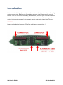
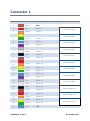
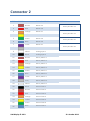
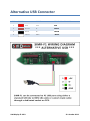
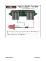
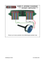
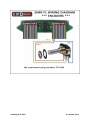
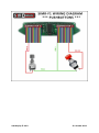
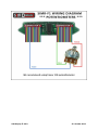
SIMR-F1
USER MANUAL
Rev A. - C.
SIM Display © 2013
22. October 2013
Introduction
SIM Race F1 has 21 bright lights and gear indicator. You can display various data on four digit
displays on each side. Brightness is adjustable in software. Direct connection for up to 32
buttons. You can also connect encoders, potentiometers, external lights and rotary switches.
We recommend to connect buttons and rotary switches to take the full advantages of
display. Device requires power for its operation and it needs to be plugged into USB port.
WARNING:
Please unplug device from your PC before making any connections !!!
SIM Display © 2013
22. October 2013
Connector 1
PIN
COLOR
BASIC FUNCTION
1
Brown
GND
2
Red
Button 1
3
Orange
Button 2
4
Yellow
Button 3
5
Green
Button 4
6
Blue
Button 5
7
Violet
Button 6
8
Gray
Button 7
9
White
Button 8
10
Black
Button 9
11
Brown
Button 10
12
Red
Button 11
13
Orange
Button 12
14
Yellow
Button 13
15
Green
Button 14
16
Blue
Button 15
17
Violet
Button 16
18
Gray
Button 17
19
White
Button 18
20
Black
Button 19
21
Brown
Button 20
22
Red
Button 21
23
Orange
Button 22
24
Yellow
Button 23
25
Green
Button 24
26
Blue
+5V
OPTIONAL
Rotary Encoder 1
Rotary Encoder 2
Rotary Encoder 3
Rotary Encoder 4
Rotary Encoder 5
Rotary Encoder 6
Rotary Encoder 7
Rotary Encoder 8
Rotary Encoder 9
Rotary Encoder 10
Rotary Encoder 11
Rotary Encoder 12
SIM Display © 2013
22. October 2013
Connector 2
PIN
COLOR
BASIC FUNCTION
1
Brown
Button 25
2
Red
Button 26
3
Orange
Button 27
4
Yellow
Button 28
5
Green
Button 29
6
Blue
Button 30
7
Violet
Button 31
8
Gray
Button 32
9
White
Analog Input 1
10
Black
Analog Input 2
11
Brown
Rotary Switch 1
12
Red
Rotary Switch 2
13
Orange
Rotary Switch 3
14
Yellow
Rotary Switch 4
15
Green
Rotary Switch 5
16
Blue
Rotary Switch 6
17
Violet
Rotary Switch 7
18
Gray
Rotary Switch 8
19
White
Rotary Switch 9
20
Black
External LED 1
21
Brown
External LED 2
22
Red
External LED 3
23
Orange
External LED 4
24
Yellow
External LED 5
25
Green
External LED 6
26
Blue
External LED 7
OPTIONAL
Rotary Encoder 13
Rotary Encoder 14
Rotary Encoder 15
Rotary Encoder 16
SIM Display © 2013
22. October 2013
Alternative USB Connector
PIN
COLOR
NAME
STANDARD USB WIRE
1
Red
VCC
RED
2
Brown
D-
WHITE
3
Black
D+
GREEN
4
White
GND
BLACK
SIM Display © 2013
22. October 2013
SIM Display © 2013
22. October 2013
SIM Display © 2013
22. October 2013
SIM Display © 2013
22. October 2013
SIM Display © 2013
22. October 2013
SIM Display © 2013
22. October 2013
SIM Display © 2013
22. October 2013
SIM Display © 2013
22. October 2013
Encoders Configuration Software
Example: We are using two rotary encoders. Please see picture below for proper
setup in software:
SIM Display © 2013
22. October 2013