1
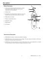
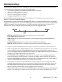
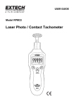
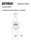
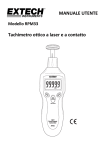
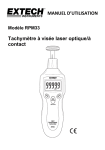
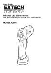
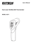
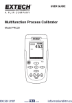
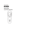
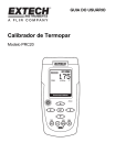
USER GUIDE Model RPM33 Laser Photo / Contact Tachometer Introduction Congratulations on your purchase of the Extech Laser Photo / Contact Tachometer, Model RPM33. The RPM33 digital tachometer offers fast and accurate measurements of the following: Rotational speed (RPM) Total Revolutions (REV) Frequency (Hz) Surface Speed (meters per minute, inchers per minute, feet per minute, yards per minute) Length (meters, inches, feet, and yards) Features include wide measurement range, high resolution, easy‐to‐read backlit LCD, MAX‐MIN‐ AVG memory, Record/Recall readings, and Laser sighting. This device is shipped fully tested and calibrated and, with proper use, will provide years of reliable service. Please visit our website (www.extech.com) to check for the latest version of this User Guide 2 RPM33-en-EU_V1.3 4/13 Description Meter Description 1. Surface (circumference) wheel accessory is shown connected to shaft (rubber cone and concave accessories are also supplied) 2. Adaptor shaft 3. Removable collar (Photo sensor and laser source are located at the top of the meter under this collar) 4. MEM (Memory) button 5. Battery compartment (rear) 6. MEASURE button 7. MODE button 8. LCD Display Push‐button Description MEM (Memory) button: Used to Record/Recall readings MEASURE button: Press and hold to take readings. The Laser pointer will switch on for Photo tachometer measurements when pressed MODE button: Press momentarily to switch measurement units. Press and hold for 2 seconds to switch between Surface Speed and Length measurement modes 3 RPM33-en-EU_V1.3 4/13 Safety WARNING! Do not directly view or direct the laser pointer toward an eye. Low power visible lasers do not normally present a hazard, but present potential for hazard if viewed directly for extended periods of time. The Laser in this unit complies with: FDA 21 CFR 1040.10 and 1040.11, IEC 60825‐1 (2001‐2008) Edition 1.2. EN 60825‐ 1:1994/A11:1996/A2:2001/A1:2002 CAUTION! Rotating and linear moving objects can be dangerous. Use extreme care. 4 RPM33-en-EU_V1.3 4/13 Preparing for Measurements Non‐Contact (Photo) Tachometer Preparation 1. Apply a square piece of reflective tape to the surface of the object under test (nominal tape size: 0.5”/12mm). Be sure to affix the tape as close to the outer edge of the object under test as possible. See diagram below. 2. If not already done, unscrew and remove the meter collar (item number 3 in the Description section diagram) 3. Proceed to the “Taking Measurements” section below. Contact Tachometer Preparation 1. If not already done, attach the collar (item number 3 in the Description section diagram) to the meter. 2. Slide the contact adaptor onto the tachometer’s shaft. Be sure to align the adaptor with the alignment pin on the shaft of the contact adaptor. 3. Attach a contact measurement accessory (cone, wheel, or concave accessory) onto the contact adaptor. 4. For Contact operation the meter can measure Surface Speed or Length. Read the section titled “Surface Speed and Length Measurement Modes” later in this guide for details. 5. Follow the steps in the “Taking Measurements” section below. 5 RPM33-en-EU_V1.3 4/13 Taking Measurements Non‐Contact (Photo) Tachometer Measurements 1. Prepare for the Non‐Contact measurement as described in the Measurement Preparation section above. 2. Use the MODE button (momentarily presses) to select RPM (rotations per minute) or Hz (Hertz: rotations per second) as the unit of measure. 3. Press and hold the MEASURE button to begin a measurement session. Hold the MEASURE button down for the duration of the test and release it to end the session. 4. Point the meter toward the device under test at a distance of 2" to 20" (50 to 500mm). Be sure to align the laser light beam with the reflective tape (see diagram above in previous section). 5. Verify that the ((( ))) monitor indicator appears on the LCD when the reflective tape passes through the light beam. 6. Read the measurement result from the LCD display. 7. When the MEASURE button is released the last reading will remain on the display for 5 to 10 seconds before the ‘Auto Power OFF’ feature switches the meter OFF. The HOLD display icon will switch ON. Non‐Contact (Photo tachometer) Measurement Considerations Bright ambient light may interfere with the reflected light beam. Shading the target area may be necessary in some cases. The non‐reflective area must always be larger than the reflective area. If the shaft or rotating object is normally reflective, it must be covered with black tape or paint before the reflective tape is applied. To improve repeatability of low RPM measurements, apply additional squares of reflective tape. Divide the reading shown on the display by the number of pieces of reflective tape squares to calculate the actual RPM. 6 RPM33-en-EU_V1.3 4/13 Contact Tachometer Measurements 1. Prepare for Contact measurements as described in the Measurement Preparation section above. 2. Determine if Surface Speed or Length measurements are to be made. Refer to the section “Surface Speed and Length Measurement Modes” later in this guide for details. 3. Press and hold the MEASURE button. 4. Touch the measurement accessory (cone, wheel, or concave accessory) to the object under test. 5. Read the measurement result from the LCD display. 6. When the Measure button is released the last reading will remain on the display for 5 to 10 seconds before the ‘Auto Power OFF’ feature switches the meter OFF. The HOLD display icon will switch ON. 7. To change the unit of measure, first release the MEASURE button. Then, momentary presses of the MODE button will step through the available units. Refer to the Specifications section and to the section below entitled “Surface Speed and Length Measurement Modes” for units of measure details. Surface Speed, Length, and Revolutions Measurement Modes 1. To switch between the Surface Speed and the Length measurement modes, press and hold the MODE button for two seconds. 2. The units of measure available in the Surface Speed mode are meters per minute (M/M), inches per minute (I/M), feet per minute (F/M), and yards per minute (Y/M). Step through the units selections with momentary presses of the MODE button. 3. The units of measure available in the Length measurement mode are meters (M), inches (I), feet (F), yards (Y), and revolutions (REV). The Revolutions (REV) mode is handy as a counter for use with custom sized wheel attachments to count (tally) wheel rotations. Step through the units selections with momentary presses of the MODE button. 7 RPM33-en-EU_V1.3 4/13 Datalog Readings The RPM33 can log up to ten (10) “reading sets” for each measurement session (for each unit of measure display). A reading set consists of four (4) values: Initial reading (reading recorded when MEM button is pressed) Maximum reading (MAX icon shown) Minimum reading (MIN icon shown) Average reading (AVG icon shown) This totals 400 stored readings (4 values per reading set * 10 reading sets per measurement session * 10 units of measure displays) A measurement session starts when the MEASURE button is pressed and ends when it is released. Logging starts when the user presses the MEM button momentarily and ends when the MEAUSURE button is released. The number shown on the LCD in the lower right hand corner (data 0 – 9) indicates the current memory location. See example time‐line diagram below. MEAS‐01: MEASURE button is pressed (measurement session begins) A: No logging during this period MEM: MEM button is pressed momentarily, initial reading is logged and MIN/MAX/AVG logging begins B: MAX/MIN/AVG readings are tracked and recorded during this period MEAS‐02: MEASURE button is released (measurement session and logging ends) 1. Press and hold the MEASURE button to begin a measurement session as described earlier. 2. While holding down the MEASURE button, press the MEM button momentarily. The reading on the display at the time of the MEM button press (initial reading) will be stored in the current reading set and the MIN/MAX/AVG tracking will begin. Note the reading set memory location on the lower right hand corner of the LCD. 3. The MIN/MAX/AVG readings are calculated over the course of the measurement session (starting from when the MEM button is pressed and ending when the MEASURE button is released). MIN/MAX/AVG readings are stored in the same reading set as the ‘initial reading’. 4. Release the MEASURE button to end the measurement session. 5. Now, momentary presses of the MEM button step through the initial reading, MAX, MIN, and AVG readings stored in the current memory location. Note that subsequent presses of the MEM button step through the remaining nine memory locations; be sure to note the memory location number when reviewing data to avoid confusion. 6. When recalling data, press and hold the MEM button to quickly jump from one reading set to another. The reading set number, on the lower right, scrolls while the MEM button is held. 8 RPM33-en-EU_V1.3 4/13 Datalogging more than one Reading Set per Measurement Session If the MEM button is pressed more than once during a measurement session, more than one reading set will be created for that measurement session (one reading set for each MEM press). This is useful if more than one ‘initial reading’ is desired for a given measurement session. The MIN/MAX/AVG values logged in each reading set represent the MIN/MAX/AVG values recorded between the MEM presses. See the time‐line example below: MEAS‐01: MEASURE button is pressed (measurement session begins) A: No logging during this period MEM01: MEM button is pressed momentarily, logging begins into location ‘Data 0’ B: Reading set ‘Data 0’ logs initial reading and MAX/MIN/AVG readings MEM02: MEM pressed again, previous log (data 0) ends and new log (data 1) begins C: Reading set ‘Data 1’ logs initial reading and MAX/MIN/AVG readings for this time period MEAS‐02: MEASURE button is released (measurement session and logging ends) Battery Replacement The low battery indication appears as BAT on the display. To replace the battery, loosen the Philips head screw securing the rear battery cover and lift the cover off. Replace the 9V battery and replace cover. Never dispose of used batteries or rechargeable batteries in household waste. As consumers, users are legally required to take used batteries to appropriate collection sites, the retail store where the batteries were purchased, or wherever batteries are sold. Disposal: Do not dispose of this instrument in household waste. The user is obligated to take end‐of‐life devices to a designated collection point for the disposal of electrical and electronic equipment. Other Battery Safety Reminders o Never dispose of batteries in a fire. Batteries may explode or leak. 9 RPM33-en-EU_V1.3 4/13 Specifications General Specifications Time base Quartz crystal Display 5‐digit LCD Display Laser light source Class 2 laser < 1mW power; Wavelength is 630 to 670nm Detecting Distance 50 to 500mm (2 to 20") Sampling Time 0.5 seconds (over 120 rpm) Tachometer accuracy ± (0.05% reading + 1digit) Memory Measurement data are stored in ‘reading sets’. A reading set consists of one (1) instantaneous measurement plus MIN/MAX/AVG readings. Ten (10) ‘reading sets’ are available per measurement session Operating Conditions 0 °C to 50 °C (32 °F to 122 °F); RH 80% Max Power Supply 9V battery Power Consumption 45mA DC approximately Weight 151g (5.3oz.) Size 160 x 60 x 42 mm (6.2 x 2.3 x 1.6") 10 RPM33-en-EU_V1.3 4/13 Measurement Range Specifications Range Resolution Accuracy Photo‐Tachometer Revolutions per minute 2 to 99,999 RPM Frequency 0 to 1666 Hz 0.1 rpm (2.0 to 9999.9 RPM) 1 rpm (> 9999 0.05% of reading + 1 rPm)* digit 1 Hz Contact‐Tachometer Revolutions per minute Surface Speed 2 to 19,999 rpm 0.1 rpm (2.0 to 9999.9 RPM) 1 rpm (> 9999 rPm)* 0 to 2000 meters per minute 1 m/min 0 to 78,720 inches per minute 1 in/min 0 to 6560 feet per minute 1 ft/min 0 to 2186 yards per minute 1 yd/min 0.1 to 1000 meters Length 0.05% of reading + 1 digit 0.1 meter 0.1 inch up to 9999.9 3.9 to 39,370 inches 1 inch > 9999 (using circumference wheel attachment) 0.3 to 3280 feet 0.1 inch 0.1 to 1093 yards 0.1 yard Revolutions (counter for custom sized 0 to 99,9999 Revolutions wheels) 1 revolution (REV) Frequency 1 Hz 0 to 1666 Hz *Note that when RPM is mixed case (rPm) it represents readings >9999 with a resolution of ‘1’ and when it is upper case (RPM) if represents the range 0.2 to 9999.9 with 0.1 resolution. Copyright © 2013 FLIR Systems, Inc. All rights reserved including the right of reproduction in whole or in part in any form www.extech.com 11 RPM33-en-EU_V1.3 4/13