1
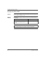
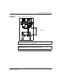
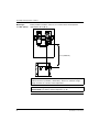
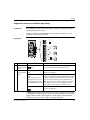
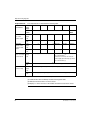
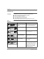
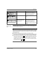
Phaseo power outage solution
User guide
W9 1489436 10 11 A01
03/2008
2
Table of Contents
Safety Information . . . . . . . . . . . . . . . . . . . . . . . . . . . . . . . . . . . . 5
About the Book . . . . . . . . . . . . . . . . . . . . . . . . . . . . . . . . . . . . . . . 7
Chapter 1
Overview . . . . . . . . . . . . . . . . . . . . . . . . . . . . . . . . . . . . . . . . . . . . 9
Overview . . . . . . . . . . . . . . . . . . . . . . . . . . . . . . . . . . . . . . . . . . . . . . . . . . . . . . . . 9
Overview of the solution . . . . . . . . . . . . . . . . . . . . . . . . . . . . . . . . . . . . . . . . . . . 10
Presentation of Battery Modules ABL 8BPK24A•• . . . . . . . . . . . . . . . . . . . . . . . 11
Presentation of Battery control modules ABL 8BBU24•00. . . . . . . . . . . . . . . . . 12
Chapter 2
Choice of solution components . . . . . . . . . . . . . . . . . . . . . . . . 15
Choice of components. . . . . . . . . . . . . . . . . . . . . . . . . . . . . . . . . . . . . . . . . . . . . 15
Chapter 3
Implementation stages. . . . . . . . . . . . . . . . . . . . . . . . . . . . . . . . 19
Implementation stages . . . . . . . . . . . . . . . . . . . . . . . . . . . . . . . . . . . . . . . . . . . . 19
Chapter 4
Assembly and temperature conditions . . . . . . . . . . . . . . . . . . 21
Presentation . . . . . . . . . . . . . . . . . . . . . . . . . . . . . . . . . . . . . . . . . . . . . . . . . . . . 21
Mounting of the Battery module . . . . . . . . . . . . . . . . . . . . . . . . . . . . . . . . . . . . . 22
Mounting of Battery control module. . . . . . . . . . . . . . . . . . . . . . . . . . . . . . . . . . . 26
Chapter 5
Wiring. . . . . . . . . . . . . . . . . . . . . . . . . . . . . . . . . . . . . . . . . . . . . . 27
Overview . . . . . . . . . . . . . . . . . . . . . . . . . . . . . . . . . . . . . . . . . . . . . . . . . . . . . . .
24 VDC circuit wiring . . . . . . . . . . . . . . . . . . . . . . . . . . . . . . . . . . . . . . . . . . . . . .
Diagnostics contact and inhibition input wiring . . . . . . . . . . . . . . . . . . . . . . . . . .
Wiring of an auto power off circuit of the Battery Module . . . . . . . . . . . . . . . . . .
Chapter 6
27
28
33
35
Setup . . . . . . . . . . . . . . . . . . . . . . . . . . . . . . . . . . . . . . . . . . . . . . 37
Overview . . . . . . . . . . . . . . . . . . . . . . . . . . . . . . . . . . . . . . . . . . . . . . . . . . . . . . .
User interface . . . . . . . . . . . . . . . . . . . . . . . . . . . . . . . . . . . . . . . . . . . . . . . . . . .
First powering on / Minimum setup . . . . . . . . . . . . . . . . . . . . . . . . . . . . . . . . . . .
The SETTINGS Menu . . . . . . . . . . . . . . . . . . . . . . . . . . . . . . . . . . . . . . . . . . . . .
Settings transfer by memory card type SR2 MEM02 . . . . . . . . . . . . . . . . . . . . .
37
38
40
42
47
3
Chapter 7
Diagnostic. . . . . . . . . . . . . . . . . . . . . . . . . . . . . . . . . . . . . . . . . . 51
Overview . . . . . . . . . . . . . . . . . . . . . . . . . . . . . . . . . . . . . . . . . . . . . . . . . . . . . . . 51
Diagnostic . . . . . . . . . . . . . . . . . . . . . . . . . . . . . . . . . . . . . . . . . . . . . . . . . . . . . . 52
Faults - causes - remedies. . . . . . . . . . . . . . . . . . . . . . . . . . . . . . . . . . . . . . . . . . 55
Chapter 8
Operation timing diagrams . . . . . . . . . . . . . . . . . . . . . . . . . . . . 57
Overview . . . . . . . . . . . . . . . . . . . . . . . . . . . . . . . . . . . . . . . . . . . . . . . . . . . . . . . 57
Timed function . . . . . . . . . . . . . . . . . . . . . . . . . . . . . . . . . . . . . . . . . . . . . . . . . . . 58
All functions (timed or max) : voltage feedback before module cut-off . . . . . . . . 59
Max function with long power outage (complete discharge of Battery module). . 60
Output behaviour in the case of overload or short-circuit . . . . . . . . . . . . . . . . . . 61
Chapter 9
Maintenance . . . . . . . . . . . . . . . . . . . . . . . . . . . . . . . . . . . . . . . . 63
Overview . . . . . . . . . . . . . . . . . . . . . . . . . . . . . . . . . . . . . . . . . . . . . . . . . . . . . . . 63
SERVICE menu . . . . . . . . . . . . . . . . . . . . . . . . . . . . . . . . . . . . . . . . . . . . . . . . . . 64
Battery modules replacement . . . . . . . . . . . . . . . . . . . . . . . . . . . . . . . . . . . . . . . 66
Appendices
. . . . . . . . . . . . . . . . . . . . . . . . . . . . . . . . . . . . . . . . . . . . . . . 67
Overview . . . . . . . . . . . . . . . . . . . . . . . . . . . . . . . . . . . . . . . . . . . . . . . . . . . . . . . 67
Appendix A
Characteristics . . . . . . . . . . . . . . . . . . . . . . . . . . . . . . . . . . . . . . 69
Overview . . . . . . . . . . . . . . . . . . . . . . . . . . . . . . . . . . . . . . . . . . . . . . . . . . . . . . . 69
Electrical Characteristics of the Battery control modules. . . . . . . . . . . . . . . . . . . 70
Operating and environmental characteristics of Battery control modules . . . . . . 71
Electrical characteristics of the Battery modules . . . . . . . . . . . . . . . . . . . . . . . . . 72
Operating and environmental characteristics of Battery modules . . . . . . . . . . . . 73
Appendix B
Battery general information . . . . . . . . . . . . . . . . . . . . . . . . . . . 75
Battery Generalities . . . . . . . . . . . . . . . . . . . . . . . . . . . . . . . . . . . . . . . . . . . . . . . 75
Appendix C
FAQ . . . . . . . . . . . . . . . . . . . . . . . . . . . . . . . . . . . . . . . . . . . . . . . 77
FAQ . . . . . . . . . . . . . . . . . . . . . . . . . . . . . . . . . . . . . . . . . . . . . . . . . . . . . . . . . . . 77
4
Glossary
. . . . . . . . . . . . . . . . . . . . . . . . . . . . . . . . . . . . . . . . . . . . . . . 79
Index
. . . . . . . . . . . . . . . . . . . . . . . . . . . . . . . . . . . . . . . . . . . . . . . 81
Safety Information
§
Important Information
NOTICE
Read these instructions carefully, and look at the equipment to become familiar with
the device before trying to install, operate, or maintain it. The following special
messages may appear throughout this documentation or on the equipment to warn
of potential hazards or to call attention to information that clarifies or simplifies a
procedure.
The addition of this symbol to a Danger or Warning safety label indicates
that an electrical hazard exists, which will result in personal injury if the
instructions are not followed.
This is the safety alert symbol. It is used to alert you to potential personal
injury hazards. Obey all safety messages that follow this symbol to avoid
possible injury or death.
DANGER
DANGER indicates an imminently hazardous situation, which, if not avoided, will
result in death or serious injury.
WARNING
WARNING indicates a potentially hazardous situation, which, if not avoided, can result
in death, serious injury, or equipment damage.
CAUTION
CAUTION indicates a potentially hazardous situation, which, if not avoided, can result
in injury or equipment damage.
W9 1489436 10 11 A01 03/2008
5
Safety Information
PLEASE NOTE
Electrical equipment should be installed, operated, serviced, and maintained only by
qualified personnel. No responsibility is assumed by Schneider Electric for any
consequences arising out of the use of this material.
© 2008 Schneider Electric. All Rights Reserved.
6
W9 1489436 10 11 A01 03/2008
About the Book
At a Glance
Document Scope
Related
Documents
User Comments
W9 1489436 10 11 A01 03/2008
This user manual contains the necessary information for the implementation of the
Phaseo power outage solution.
Title of Documentation
Reference Number
Phaseo Universal power supply instruction sheet
1489414_01
Battery Control module instruction sheet
1489436_01
Battery module instruction sheet
1489436_06
We welcome your comments about this document. You can reach us by e-mail at
[email protected]
7
About the Book
8
W9 1489436 10 11 A01 03/2008
Overview
1
Overview
Introduction
This chapter presents the constitutive elements of the Phaseo power outage
solution.
What's in this
Chapter?
This chapter contains the following topics:
W9 1489436 10 11 A01 03/2008
Topic
Page
Overview of the solution
10
Presentation of Battery modules ABL 8BPK24A••
11
Presentation of Battery control modules ABL 8BBU24•00
12
9
Overview
Overview of the solution
Introduction
The Phaseo power outage solution allows the 24 VDC supply of the installation (or
with one part) in case there is a network voltage cut-off:
During the entire duration of the cut-off, in order to allow :
the continuity of the installation service.
During a limited time, in order to allow :
data backup,
the fallback of the actuators,
the startup of generators,
operating system shut-down,
data transmission by remote monitoring...
Constitution of
the solution
+
+
1
2
3
Marker
Description
Reference
1
Phaseo Universal power supply
ABL 8•P•24••0
2
Battery control module
ABL 8BBU24•00
3
Battery module
ABL 8BPK24A••
CAUTION
RISKS OF EQUIPMENT DAMAGE
When the supply is provided by the Battery module, the voltage is not regulated
and can vary between 19 VDC and 28 VDC. It is suitable to check carefully that
the supplied circuits can support a voltage tension between these 2 values.
The use of batteries other than those included in the Battery modules
ABL 8BPK24A•• is not possible (risk of battery deterioration).
Failure to follow these instructions can result in injury or equipment damage.
10
W9 1489436 10 11 A01 03/2008
Overview
Presentation of Battery Modules ABL 8BPK24A••
Introduction
Each Phaseo Battery module consists of:
2 lead sealed batteries mounted serially,
one fuse protection (automobile type).
The Phaseo Battery module range proposes 3 different battery capacities according
to the backup time and the current required for the application desired. See Choice
of components, p. 15.
Note: The Phaseo battery modules do not require maintenance. In the case of
failure, please replace the module set.
Description
The scheme below presents the structure of the Phaseo Battery module:
1
2
3
4
Marker Description
3.2 Ah
1
Bolt mounting by vertical or horizontal panel
Metal protective housing
Rail mounting
7 Ah
12 Ah
-
(1)
2
Protection fuse carrier and
shutdown of module
1 fuse carrier
2 fuse carriers
3
Terminal block of the 24 VDC
output voltage
1 block
2 blocks
10 mm2 screw terminal block
10 mm2 screw
terminal block
Fuse storage attachment
1 attachment
2 attachments
4
(1)Kit
usage ABL 1A02
Note: The fuses are delivered with the module, but not mounted, please mount
them by following the implementation. See Implementation stages, p. 19.
W9 1489436 10 11 A01 03/2008
11
Overview
Presentation of Battery control modules ABL 8BBU24•00
Introduction
The battery Control modules ABL 8BBU24•00 allowing the following functions :
Optimize the use and life of the batteries:
charge if necessary and as a function of the ambient temperature,
shutdown of the Battery module before the deep discharge (1),
maintenance charge to compensate for self-discharge,
measurement of Battery module ageing
Automatic switch without interruption between power supply and battery:
adjustable operating time on the battery (holding time),
diagnostic of the system state.
The range of the Phaseo battery Control module consists of 2 modules according to
the maximum usage current (20 A or 40 A). See Choice of components, p. 15.
(1)Important:
When the Battery control module ABL 8BBU24•00 is not supplied by
the power supply ABL 8RP••/ABL 8WP••, the Battery module ABL 8BPK24A••
continues to provide a residual current necessary for the power supply of the module
electronics.
In the case of prolonged absence of the power supply voltage in the IN+ and INterminals, it is advisable to unplug the Battery module by removing its fuse(s) in
order to avoid deep discharge.
When this power-off is expected (machine transport or requested power-off), it is
also recommended to turn on the entire control module and Battery module until the
batteries are charged completely (battery icon OK on the display).
It is also possible to insert a contactor between the Battery module and the Battery
control module in order to execute an automatic cut-off (see Wiring of an auto power
off circuit of the Battery Module, p. 35).
12
W9 1489436 10 11 A01 03/2008
Overview
Description
The scheme below presents the structure of the Battery control module:
6
1
7
2
8
3
9
4
5
W9 1489436 10 11 A01 03/2008
N°
Description
1
Click-on marker label
2
LCD display
3
Browse selection button
4
Grounded lug
5
24 VDC I/Os and the Battery module terminals
6
Mounting flange on DIN rail
7
Memory card (SR2 MEM02) slot to backup and copy configuration settings
8
2-point removable screw terminal block for the input terminal of the 'inhibition of the
Battery module voltage'
9
9-point removable screw terminal block for the input terminal of diagnostic contacts
(power supply presence, alarm and battery presence)
13
Overview
14
W9 1489436 10 11 A01 03/2008
Choice of solution components
2
Choice of components
Introduction
The application settings to be considered in the component choice are :
the current to be provided during t2 backup (holding current),
the t2 backup time (see timing diagram below).
AC input voltage
t
DC output voltage
t2
Guidance in
choosing
t
According to the necessary holding current and desired backup time, the table below
indicates the associations of appropriate modules.
Note: This table is based on the characteristics of new Battery module. At the end
of life, once the autonomy of a battery is capable of being divided by 2, it is suitable
to take this into account when choosing the module(s) by multiplying the holding
time by 2 if desired to guarantee the holding time during the life of the modules. For
backup times greater than 5 hours, refer to the table on the following page.
W9 1489436 10 11 A01 03/2008
15
Choice of components
Holding t2 holding time (see timing diagram)
current Seconds
Minutes
5
10 30 1
2
3
4
5
6
7
8
9
10 15 20 30 40 50 1
2
3
5
1
2
2
2
2
2
2
2
2
2
2
2
2
2
2
2
2
2
2
2
2
3
3
2A
1
2
2
2
2
2
2
2
2
2
2
2
2
2
2
2
2
2
2
2
3
4
4
3A
1
2
2
2
2
2
2
2
2
2
2
2
2
2
2
2
2
2
3
3
3
4
4
5
4A
1
2
2
2
2
2
2
2
2
2
2
2
2
2
2
2
2
3
3
3
3
4
5
5
0.2
0.5
1
2
Hours
1A
0.1
5A
1
2
2
2
2
2
2
2
2
2
2
2
2
2
2
2
2
3
3
3
4
4
5
5
6A
1
2
2
2
2
2
2
2
2
2
2
2
2
2
2
2
3
3
3
4
4
4
5
5
7A
1
2
2
2
2
2
2
2
2
2
2
2
2
3
3
3
3
3
4
4
4
4
5
8A
1
2
2
2
2
2
2
2
2
2
2
3
3
3
3
3
3
3
4
4
4
5
5
5
10 A
1
2
2
2
2
2
2
2
2
2
2
3
3
3
3
3
3
3
4
4
5
5
15 A
1
2
2
2
2
2
2
2
2
2
3
3
3
3
3
4
4
4
4
5
5
5
20 A
1
3
3
3
3
3
3
3
3
3
3
4
4
4
4
4
4
5
5
5
25 A
1
6
6
6
6
6
6
6
6
6
6
7
7
7
7
7
8
8
8
8
30 A
1
6
6
6
6
6
6
6
6
6
7
7
7
8
8
8
8
8
8
8
35 A
1
6
6
6
6
6
6
6
6
7
7
7
8
8
8
8
8
8
8
40 A
1
7
7
7
7
7
7
7
7
7
7
8
8
8
8
8
8
8
Note: Data for an ambient temperature of 20°C (68°F), the capacity of a battery
increases with temperature.
Associations proposed:
Code
Module
Battery module
Type
1
40 A Buffer Module
2
20 A Battery Control
Qty.
Type
Reference
ABL 8BUF24400
-
-
ABL 8BUF24400
ABL 8BBU24200
1
3.2 Ah
ABL 8BPK24A03
3
1
7 Ah
ABL 8BPK24A07
4
1
12 Ah
ABL 8BPK24A12
5
2
12 Ah
ABL 8BPK24A12
6
40 A Battery Control
ABL 8BBU24400
1
7 Ah
ABL 8BPK24A07
7
1
12 Ah
ABL 8BPK24A12
8
2
12 Ah
ABL 8BPK24A12
(1)
16
(1)
Reference
Solution for microbreaks (< 2 s), for more information please consult the catalog.
W9 1489436 10 11 A01 03/2008
Choice of components
Discharge
current
Battery
module
capacity
The following table indicates the likely discharge current (in A) as a function of the
desired holding time and the capacity of the Battery module:
t2 holding time (see timing diagram)
Minutes
Hours
5
10
15
20
25
30
35
40
45
1
2
3
5
8
10
3.2 Ah
8.4
6.3
4.9
4.2
3.6
3.1
2.8
2.6
2.3
2.0
1.1
0.86 0.50 0.38 0.30 0.16
7 Ah
18.2 13.6 11.0 9.0
7.7
6.8
6.1
5.6
5.0
4.2
2.5
1.8
1.2
0.80 0.64 0.35
12 Ah
31.3 23.4 18.6 15.5 13.3 11.6 10.5 9.6
8.6
7.1
4.2
3.1
2.0
1.3
1.1
20
0.60
Note: Data for an ambient temperature of 20°C (68°F).
Note: The holding times are multiplied by the number of parallel Battery modules
(3 MAXI).
W9 1489436 10 11 A01 03/2008
17
Choice of components
18
W9 1489436 10 11 A01 03/2008
Implementation stages
3
Implementation stages
Operation to be
followed
Stage
To implement the Phaseo power outage solution proceed as follows:
Action
See
1
Check that the products commissioned correspond to
commanded references.
Choice of solution components, p. 15
2
Cut the primary power supply network.
-
3
Install the Phaseo power supply.
Service instruction delivered with the Phaseo
power supply, (Related Documents, p. 7).
4
Install the Battery control module.
Mounting of Battery control module, p. 26
5
Install the power supply.
connect the power supply to the network protection,
wire, if necessary, the diagnostics relay,
place the power supply switch to the MANU restart
mode.
Service instruction delivered with the Phaseo
power supply, (Related Documents, p. 7).
6
Install the Battery module(s).
Do not plug in the fuse(s) for the moment.
Mounting of the Battery module, p. 22
7
Wiring:
connect the Battery control module and the Battery
module(s).
wire, if necessary, the 9-point terminal block of the
Battery control module.
8
Plug in the fuse(s) of the Battery module, then turn on the
power supply.
Note : A light sparkle may appear when plugging in the
fuses. This is not a failure.
-
9
Adjust and check the power supply:
adjust, if necessary, the output voltage,
check that the 2 lights are green.
Instruction sheet delivered with the Phaseo
power supply, (Related Documents, p. 7).
W9 1489436 10 11 A01 03/2008
24 VDC circuit wiring, p. 28
Diagnostics contact and inhibition input
wiring, p. 33
19
Implementation stages
Stage
Action
See
10
Set up the Battery control module.
First powering on / Minimum setup, p. 40
11
Wait for full charge of the Battery module before carrying
out a network outage test (up to 72h for a first
commissioning).
-
12
Check that the screen of the Battery control module is
green. It is possible to check also the information provided
by the output relays of the 9-point terminal block.
Diagnostic, p. 51
CAUTION
RISK OF EQUIPMENT DAMAGE
The power supply ABL 8•P must be configured in the manual reset mode (selector
on MANU). If the power supply is configured in the automatic reset mode (AUTO),
the Battery control module can be destroyed in the case of overcurrent in its output.
Failure to follow these instructions can result in injury or equipment damage.
20
W9 1489436 10 11 A01 03/2008
Assembly and temperature
conditions
4
Presentation
Introduction
This chapter presents the assembly and assembly conditions to be considered in the
installation of Battery modules and the Battery control module.
What's in this
Chapter?
This chapter contains the following topics:
W9 1489436 10 11 A01 03/2008
Topic
Page
Mounting of the Battery module
22
Mounting of Battery control module
26
21
Assembly and temperature conditions
Mounting of the Battery module
Important
Install the Battery module(s) in the freshest possible location. This prolongs their life
(see Lead Battery Generalities, p. 76).
Choice of
mounting
Depending on the temperature inside the enclosure, the following mountings are
recommended:
Temperature inside the enclosure = T
Mounting
T ≤ 40 °C (104°F)
Battery module inside the enclosure
T > 40 °C (104°F)
(No regulation of the temperature inside the
enclosure)
Battery module outside the enclosure
Note: The mounting with the Battery module inside the enclosure is favored in
order to allow the charge to be corrected as a function of temperature.
22
W9 1489436 10 11 A01 03/2008
Assembly and temperature conditions
Mounting 1:
T ≤ 40°C (104°F)
Battery module below the enclosure :
2
MANU
– +
1
AUTO
OF F
MEM
2
28.8 V
Iout
3
4
5
A la rm
24V
PS U
1
Uout
6
OUT
+
+
7
8
– +
IN
9
– +
+ + – –
–
IN
–
OUT
–
< 5 m (196.85 in)
+–
Note: The charge voltage is adjusted automatically as a function of the
temperature measured by the control module.
Note: This mounting corresponds to the Battery module temperature setup in
Differential mode (see Battery module temperature, p. 46).
W9 1489436 10 11 A01 03/2008
23
Assembly and temperature conditions
Mounting 2:
T > 40°C (104°F)
Battery module outside the enclosure, in a location where the temperature
approximates 20°C (68°F):
2
MANU
– +
1
AUTO
OF F
MEM
2
28.8 V
Iout
3
4
5
A la rm
24V
PS U
1
Uout
6
OUT
+
+
7
8
– +
IN
9
– +
+ + – –
–
IN
–
OUT
–
< 5 m (196.85 in)
+–
Note: This solution is only recommended if it is impossible to lower the temperature
inside the enclosure (ventilation, climatization). There is no automatic charge
voltage correction as a function of the temperature.
Note: This mounting corresponds to the Battery module temperature setup in
Absolute mode (see Battery module temperature, p. 46).
24
W9 1489436 10 11 A01 03/2008
Assembly and temperature conditions
Mounting
position
The scheme below illustrates the positions to be considered during the mounting of
the Battery modules:
90°
90°
+–
+–
+–
180°
0°
180°
+–
0°
270°
Dimensions and
mounting
The Battery modules are mounted by screw or rail
ABL 8BPK24A03.
270°
for the module
The module dimensions and drilling templates of mounting holes are located in the
instruction sheet of the Battery modules. See Related Documents, p. 7.
W9 1489436 10 11 A01 03/2008
25
Assembly and temperature conditions
Mounting of Battery control module
Rail
The Battery control modules must be installed on a rail
. The scheme below
provides the characteristics and the references of the compatible rails for the
mounting of the modules:
AM1 ED200
AM1 DP200
DZ5 MB200
35
1.38
AM1 DE200
IEC/EN 60715
15
0.59
15
0.59
7,5
0.30
60/2.36
86/3.39
2
2
1
2
+
6
8
5
6
IN
– +
+
7
– +
OUT
+
4
Alarm
5
IN
– +
+
OUT
+
+
–
Mounting/
Dismantling
–
OUT
–
–
IN
–
8
OUT
–
5
0.2
6
0.24
IN
– +
7
9
9
– +
mm
inch
3
3
4
– +
1
PSU
– +
1
141/5.55
OFF
2
PSU
141/5.55
125/4.92
1
OFF
MEM
MEM
Alarm
160/6.3
– +
11/0.43
Dimensions
The scheme below illustrates the mounting (left) and the dismantling (right) of the
Battery control module on a rail
:
1
1
2
2
1
1
26
W9 1489436 10 11 A01 03/2008
Wiring
5
Overview
Introduction
This chapter presents the elements necessary for the wiring of Battery modules and
the Battery control module.
What's in this
Chapter?
This chapter contains the following topics:
Topic
24 VDC circuit wiring
W9 1489436 10 11 A01 03/2008
Page
28
Diagnostics contact and inhibition input wiring
33
Wiring of an auto power off circuit of the Battery module
35
27
Wiring
24 VDC circuit wiring
Preliminaries
CAUTION
RISKS OF EQUIPMENT DAMAGE
The input terminals of the Battery control module must, by obligation, be connected
to the output terminals of the ABL8 supply or other Phaseo ABL8 modules.
Failure to follow these instructions can result in injury or equipment damage.
CAUTION
RISKS OF EQUIPMENT DAMAGE
Consider the tightening torque indicated in this document to avoid hazardous
terminal block warm-up.
Do not allow liquids or foreign bodies to penetrate inside the product.
Failure to follow these instructions can result in injury or equipment damage.
Read carefully the regulations and recommendation of the following wiring :
Check that the operating and environmental conditions are well situated in the
specified zones, see Characteristics, p. 69.
As a function of the charge, a downstream protection circuit may be required. The
selectivity module ABL 8PRP24100 fulfils this role.
Use wire end ferrules for the wires.
Use the wires in the appropriate section in order to consider the demands in
current and voltage :
input and output of the Battery control module and the Battery module:
0.5...10 mm2 (AWG 20...8) with wire end ferrules.
Connect the junction of the functional earth by means of a 10 mm² (AWG 6)
section conductor.
28
W9 1489436 10 11 A01 03/2008
Wiring
Tightening
torque
The scheme below indicates the screws to be used and the tightening torque to be
considered:
MEM
ABL8BBU24200
IN
+
OUT
+
–+
+
IN
–
–
4
5
6
7
8
9
PSU
2
3
–+
Alarm
1
–+
1
2
– + OFF
+ -
Ø 2.5 mm (0.10 in)
0.4 Nm (3.6 lb-in)
OUT
–
Ø 4.5 mm (0.18 in)
1.7 Nm (15 lb-in)
Internal schemes
+
+
+
-
IN
+
IN
-
1
OFF
2
11
1
14
2 PSU
12
3
21
4
24
5 ALARM
22
6
31
7
34
8
32
9
+
+
OUT
+
OUT
-
Note: The IN- et OUT - terminals are internally relinked.
W9 1489436 10 11 A01 03/2008
29
Wiring
Basic wiring
LV C HV
100
120
200
500
MEM
ABL8BBU24200
2
–
MANU
+
1
AUTO
OFF
+ -
2
3
Iout
4
5
IN
+
+
OUT
+
+
6
7
+
–
Alarm
28.8V
8
–
24V
PSU
1
Uout
9
– +
–
+ +
IN
–
1
OUT
–
2
N°
Description
1
Non-protected output
2
Protected output, for circuit requiring continuous supply in the case of primary
network shut-off.
Important: The rated current delivered on the control module output may reach
20 A (ABL 8BBU24200) or 40 A (ABL 8BBU24400) in a prolonged manner,
regardless of the current delivered by the supply.
CAUTION
RISKS OF EQUIPMENT DAMAGE
The polarities of the Battery module must be considered. A polarity inversion can
lead to destruction or malfunction of the Battery module.
Failure to follow these instructions can result in injury or equipment damage.
30
W9 1489436 10 11 A01 03/2008
Wiring
Maximal
capacitive load
on the supply
output
The non-protected circuits connected directly to the supply (marker 1) must have a
capacitive load less than the values in the table below:
Power Supply
Maximal capacity of the non-protected load (μF)
ABL 8RPS24030
30,000
ABL 8RPS24050
50,000
ABL 8RPS24100
100,000
ABL 8RPM24200
100,000
ABL 8WPS24400
100,000
CAUTION
RISK OF EQUIPMENT DAMAGE
When the maximal values of the capacitive load connected to the power supply
output are not considered (non-protected output), the Battery control module can
be destroyed if an overload is produced on the protected output.
Failure to follow these instructions can result in injury or equipment damage.
W9 1489436 10 11 A01 03/2008
31
Wiring
Wiring of several
Battery modules
(max 3)
In the case of parallel wiring of several Battery modules, the wiring is constructed
as follows:
LV C HV
100
120
200
500
MEM
ABL8BBU24200
+ -
–
2
+ -
+
1
+ -
OFF
+ -
AUTO
MANU
2
3
Iout
4
5
IN
+
+
OUT
+
+
6
7
+
–
Alarm
28.8V
8
–
24V
PSU
1
Uout
9
–
+
–
IN
–
OUT
–
+ +
1
32
2
N°
Description
1
Non-protected output
2
Protected output for circuit requiring continuous supply in the case of primary
network shut-off.
W9 1489436 10 11 A01 03/2008
Wiring
Diagnostics contact and inhibition input wiring
Introduction
Three diagnostics relays inform if the supply is operating, if the Battery module is
operating and if there is an alarm.
The two removable screw terminal blocks accept wires of section 0.14...1 mm2
(AWG 26...16) with wiring end ferrule.
2
4
5
OUT
+
+
6
7
8
– +
IN
– +
+
Alarm
3
9
OFF
2
1
2
–
–
OUT
–
11
14
12
21
24
22
3
4
5
IN
– +
PSU
1
1
Alarm
OFF
2
PSU
1
– +
MEM
– +
Description
6
8
– +
7
9
31
34
32
N°
Connector
Relay
Contact description
1
Inhibition input
(2-point terminal
block)
Inhibition:
Open circuit terminals: Operating Battery module
Diagnostics relay
(9-point terminal
block)
Power Supply mode:
PSU
Contact 11/14 closed: The power supply provides the
current to the application
Alarm:
Alarm
Note : The alarm can be
suppressed in some cases
by deactivating some tests
(see SERVICE menu, p. 64).
Contact 21/22 closed: output overload / absence of Battery
module / defective Battery module / inhibited Battery module
/ capacity or battery charge insufficient for the set backup
time or non-measurable charge rate (in backup mode)
Note : the 21/22 contact is also closed when it is neither in
the backup mode nor in the Power Supply mode (new
product state or shut-off state after a backup cycle).
Backup mode:
Contact 31/14 closed: the Battery modules provide the
current to the application
2
– +
OFF
– +
Connected terminals: Off-loaded Battery module (1)
(1)Important:
the Battery module continues to provide a residual current essential
for supplying the module electronics. In the case of prolonged absence of the power
supply voltage in the IN+ and IN- terminals, it is advisable to unplug the Battery
module by removing its fuses in order to avoid deep discharge.
W9 1489436 10 11 A01 03/2008
33
Wiring
CAUTION
RISK OF EQUIPMENT DAMAGE
The pins 1 and 2 of the inhibition input terminal block must not be connected to any
other part of a circuit, they must be free of all potential.
Failure to follow these instructions can result in injury or equipment damage.
Admissible current in the relay contact:
Voltage
34
Current
24 VDC
5 mA mini
230 VAC
500 mA maxi
W9 1489436 10 11 A01 03/2008
Wiring
Wiring of an auto power off circuit of the Battery Module
Overview
The wiring present is an additionnal protection against the risk of deep discharge of
the Battery module.
This solution consists of inserting a contactor between the Battery module(s) and the
Battery control module. The contactor switches automatically in order to insulate the
Battery module of the circuit.
Contactor wiring
LV C HV
100
120
200
500
MEM
0.5A fuse
ABL8BBU24200
+ +
+
–
IN
–
13/NO
21/NC
14
22
5/L3
6
7
OUT
–
A2
8
9
–
T3/6
+
+
+
3/L2
5
+
OUT
A1
4
IN
– +
T2 / 4
–
3
Iout
Alarm
28.8V
–
24V
PSU
2
Uout
1/ L1
OFF
+ -
1
T1 / 2
2
MANU
+
1
AUTO
LC1 D32BL
W9 1489436 10 11 A01 03/2008
35
Wiring
36
W9 1489436 10 11 A01 03/2008
Setup
6
Overview
Introduction
This chapter presents the information necessary for the setup of the Battery control
module as a function of the application desired.
What's in this
Chapter?
This chapter contains the following topics:
W9 1489436 10 11 A01 03/2008
Topic
Page
User interface
38
First powering on / Minimum setup
40
The SETTINGS Menu
42
Settings transfer by memory card type SR2 MEM02
47
37
Setup
User interface
Description
1
2
Function
N°
Description
1
LCD display (3 background colours)
2
Browse selection button
The user interface allows:
During the operation visualize (see chapter Diagnostic, p. 51):
The system status (Power Supply mode / backup mode).
The status of the Battery module(s) (1).
The diagnostic information in case of failure.
During the commissioning (see The SETUP Menu, p. 42):
Setup the application.
During the maintenance and breakdown check, (see SERVICE menu, p. 64):
To inhibit certain test functions in order to allow the downgraded operation.
Test the system elements.
(1)
The measurement of the charge of the Battery module(s) is inactive during the
first charge or during the replacement of the Battery module or if this function has
been deactivated in the SERVICE menu.
38
W9 1489436 10 11 A01 03/2008
Setup
Browse rule
Use of the browse button :
Press the button
Description
Rotation
Browse the menus / Select a setting
Short pressing (< 1 s) Validation / Modification
Long pressing (2 s)
Go to a menu
Initial screen
IN 23.9V
OK
SERVICE
SETUP
2s
2s
LANG.
English?
off ?
EXIT
EXIT
<1s
<1s
W9 1489436 10 11 A01 03/2008
39
Setup
First powering on / Minimum setup
Operation to Be
Followed
The minimum setup for the system to function consists of informing the capacity of
the Battery module.
Important: This setup allows the system to function; however, to optimize the life of
the Battery module, it is strongly advisable to enter other parameters (see The
SETTINGS Menu, p. 42).
40
W9 1489436 10 11 A01 03/2008
Setup
The following scheme presents the operation to be followed during the first powering
on of the Battery control module.
ENGLISH
SETTINGS
<1s
Press to select the interface language
(scrolling on different languages)
1
2
–+
1
2
3
4
5
6
IN OUT
+
+
+
2s
1
2
–+
+
LANG.
English?
IN OUT
+
+
Turn to switch to the
following menu
1
2
–+
+
1
2
3
4
5
6
IN OUT
+
+
Press to enter the menu
1
2
3
4
5
6
Press to modify
<1s
7.0 Ah x 1?
1
2
–+
+
IN OUT
+
+
–+
+
<1s
1
2
–+
+
3.2 Ah x 1?
•••••••••
1
2
1
2
3
4
5
6
1
2
3
4
5
6
IN OUT
+
+
IN OUT
+
+
1
2
3
4
5
6
Turn to select the Battery
module capacity
Press to validate
Press to leave and return
to the main screen
EXIT
<1s
1
2
–+
+
IN OUT
+
+
1
2
3
4
5
6
IN 23.9V
At the end of this first setup, the control module starts the charge of the Battery
module(s). Since the charge rate is not measurable, the screen is orange until the
end of the charge. After 72 H maximum of powering on of the power supply set and
control module, the screen switches to green and the charge percentage of the
Battery modules is displayed (see Diagnostic, p. 51).
W9 1489436 10 11 A01 03/2008
41
Setup
The SETTINGS Menu
Introduction
The SETTINGS menu defines the settings related to the choice of components and
to the application.
Note: (*) indicates the value by default of the setting.
Menu tree
Screens
Description
See
Charge a configuration
from the memory card
(visible only if a memory
card is present)
Charging of a
configuration, p. 49
Back up a configuration in
the memory card (visible
only if a memory card is
present)
Backup of a configuration,
p. 47
Language choice
Interface language, p. 43
Battery module(s) choice
Battery module type, p. 43
Backup time setup
Backup time, p. 44
IN
21.0 V
Setup of the Battery
module activation voltage
Switching threshold, p. 44
L
2.Om ?
Setup of the link length
between the Battery
control module and the
Battery module(s).
Wiring length, p. 45
MEM
?
?
MEM
LANG.
english ?
7.0 Ah x 1?
OO:1O:OOs ?
42
W9 1489436 10 11 A01 03/2008
Setup
Screens
O
C
Description
See
Setup of the Battery
module(s) temperature
Battery module
temperature, p. 46
Tbat.=25
Interface
language
The setting LANG. defines the interface language:
Battery module
type
The setting
defines the capacity and the number of Battery module connected
to the Battery control module.
English
Français
Deutsch
Italiano
Espanol
Value
Reference
3.2 Ah x 1
ABL 8BPK24A03 x 1 1 3.2 Ah Battery module (1)
7 Ah x 1 (*)
ABL 8BPK24A07 x 1 1x 7 Ah Battery module (1)
12 Ah x 1
ABL 8BPK24A12 x 1 1 x 12 Ah Battery module (1)
3.2 Ah x 2
ABL 8BPK24A03 x 2 2 x 3.2 Ah Battery module mounted in parallel
7 Ah x 2
ABL 8BPK24A07 x 2 2 x 7 Ah Battery module mounted in parallel
12 Ah x 2
ABL 8BPK24A12 x 2 2 x 12 Ah Battery module mounted in parallel (1)
3.2 Ah x 3
ABL 8BPK24A03 x 3 3 x 3.2 Ah Battery module mounted in parallel
7 Ah x 3
ABL 8BPK24A07 x 3 3 x 7 Ah Battery module mounted in parallel
12 Ah x 3
ABL 8BPK24A12 x 3 3 x 12 Ah Battery module mounted in parallel
(1)Combinations
Description
proposed in the selected table, see Guidance in choosing, p. 15.
Note: If this parameter is badly adjusted, the charge rate and ageing test for the
Battery module indications will be erroneous.
W9 1489436 10 11 A01 03/2008
43
Setup
Backup time
The setting
defines the desired backup time. Two functions are proposed:
Timed function: back up from 10 s to 72h adjustable by 10 s steps
Max function: backup until power supply feedback or until the discharge of the
Battery module(s) (shut-off when the voltage in the Battery module terminals
reach 21 V, before the deep discharge threshold).
Timing diagram of the two functions:
Input voltage
t
Output voltage
Timed function
ts = backup time
t
ts
MAX function
t
Switching
threshold
If the power supply voltage decreases below this threshold, the control module
switches to the backup mode and the voltage delivered in the OUT+ and OUToriginates from the Battery module. In the current versions, this threshold is fixed at
21 V and is non-adjustable.
Important: To allow transition from a backup mode to the Power Supply mode, the
output voltage of the power supply must be at least greater than 1 V at the switching
threshold.
The following timing diagram illustrates the transition from the sbackup mode to the
Power Supply mode:
U power supply
1V mini
Switching threshold
Power supply mode
Power supply mode
Backup mode
t
44
W9 1489436 10 11 A01 03/2008
Setup
Wiring length
The setting
defines the length of the wires between the Battery module and
the Battery control module (in m or ft). This setting is used by the Battery control
module to calculate the voltage at the Battery module terminals.
The table below indicates the choice of possible lengths:
Unit selected
Adjustment range
Adjustment step
Default value
m
0.1...5 m
0.1 m
2m
ft
0.3...16.4 ft
0.1 ft
-
Example: the Battery module is linked to the Battery control module by two 3 m
(9.84 ft) wires (+ and -) each. The value to enter is 3 m or 9.8 ft.
W9 1489436 10 11 A01 03/2008
45
Setup
Battery module
temperature
The setting
°C defines the temperature of the Battery module(s). This setting
is used by the Battery control module in order to:
Calculate the charge rate of the Battery module(s),
Adapt the end of charge voltage in order to optimize the life of the Battery
module(s).
The possible temperature setup modes are related to the Battery module assembly
in comparison to the enclosure containing the Battery control module (see Mounting
of the Battery module, p. 22):
Mode
Mounting
Differential
Battery module inside the enclosure (the temperatures within the
proximity of the Battery modules and Battery control module develop
in same proportions)
Absolute
Battery module outside the enclosure
Description of the two available usage modes:
Differential:
The control module has a built-in sensor measuring the temperature in its
environment.
The user obtains the temperature difference estimated between the control
module and the Battery module such as:
ΔT = T Battery control module - T Battery module.
Note : The temperatures may be measured near the modules (1 cm of housing)
after the temperature has been stabilized inside the enclosure, where the
modules are mounted and then reported in the menu.
The charge voltage is adjusted automatically as a function of the temperature
measured by the control module.
Absolute:
The user enters directly the Battery module temperature.
There is no automatic charge voltage correction.
The table below indicates the possible temperature setup:
Mode
Differential
Adjutment range
0...40°C
(1)
Adjustment step
Default value
1°C
-
1°C
25°C (*)
Δ = XX
Absolute(*)
Tbat = XX
0...50°C
(1)
There is no Δ negative, the temperature of the battery Control module is always
greater than that of the Battery module.
Note: It is recommended to use the differential mode when possible.
46
W9 1489436 10 11 A01 03/2008
Setup
Settings transfer by memory card type SR2 MEM02
Introduction
The Battery control module is equipped with a memory card slot allowing the :
Execution of a backup copy of the settings,
Transfer the settings from one control module to another (repetitive equipment,
maintenance,...).
Note: All SETTINGS menu parameters as well as the test activation in the
SERVICE menu are transferred.
Backup of a
configuration
Stage
Description
1
Remove the cover.
2
Insert the memory card in the slot (module on or off).
3
Go to the SETTINGS menu.
4
Turn the button to connect to the screen below and press the button (< 1 s):
?
5
MEM
Press the button (< 1 s):
MEM
yes
6
Press the button to confirm (< 1 s):
MEM
confirm
Note : After confirmation, the data already in the memory card will be erased.
This menu does not appear if the card is blank.
7
Loading in progress:
MEM
W9 1489436 10 11 A01 03/2008
47
Setup
Stage
Description
8
End of loading:
MEM
terminal
9
Remove the memory card.
10
Place back the cover.
CAUTION
RISKS OF EQUIPMENT DAMAGE
Do not put anything in the slot of the memory card next to the card and always
close the access using the cover.
Failure to follow these instructions can result in injury or equipment damage.
48
W9 1489436 10 11 A01 03/2008
Setup
Loading of a
configuration
The table below indicates the stages to be followed:
Stage
Description
1
Remove the cover.
2
Insert the memory card in the slot (module on or off).
3
Go to the SETTINGS menu.
4
Press the button (< 1 s):
MEM
?
5
Press the button (< 1 s):
MEM
yes
6
Loading in progress:
MEM
7
End of loading:
MEM
terminal
8
Remove the memory card.
9
Place back the cover.
CAUTION
RISKS OF EQUIPMENT DAMAGE
Do not put anything in the slot of the memory card next to the card and always
close the access using the cover.
Failure to follow these instructions can result in injury or equipment damage.
W9 1489436 10 11 A01 03/2008
49
Setup
50
W9 1489436 10 11 A01 03/2008
Diagnostic
7
Overview
Introduction
This chapter presents the elements necessary for the analysis of diagnostic
information and fault as well as solutions to bring it about.
What's in this
Chapter?
This chapter contains the following topics:
W9 1489436 10 11 A01 03/2008
Topic
Page
Diagnostic
52
Faults - causes - remedies
55
51
Diagnostic
Diagnostic
Overview
The diagnostic information facilitates an easy commissioning and a rapid error
diagnostic.
The diagnostic information of the Battery control module is provided to the users in
3 forms:
LCD background screen colour:
Green OK
Orange: Warning
Red: Alarm
Diagnostic pictorial sign displayed on the screen
Diagnostics relay
Description of
the displayed
zones
The scheme below presents the different displayed zones:
1
2
3
IN 24.9V
OK
4
N°
Description
Power Supply mode
1
Backup mode
Input voltage = value of the supply output voltage
2
The state and charge level of the Battery module
3
Charge rate if measurable or alarms
(battery inhibited or disconnected)
Timed function: remaining backup
time.
Max function: backup time elapsed
since the last transition in backup
mode.
Format : hour:minute or s
4
52
Alarm on the output : overload
W9 1489436 10 11 A01 03/2008
Diagnostic
Visualisation and
relay state
Screen
color
The scheme below regroups the diagnostics information according to the state of the
Battery control module :
Display
State of diagnostics
relay
PSU
Green
Alarm
Signification
Bat
IN 24.9V
OK
11
14
12
21
24
22
31
34
32
IN 24.9V
82 %
11
14
12
21
24
22
31
34
32
Orange
IN 24.9V
11
14
12
21
24
22
31
34
32
Orange
IN 24.9V
OK
11
14
12
21
24
22
31
34
32
Orange
IN 24.9V
12 %
11
14
12
21
24
22
31
34
32
Red
IN 24.9V
NO
11
14
12
21
24
22
31
34
32
Red
IN 24.OV
11
14
12
21
24
22
31
34
32
Red
IN 24.OV
11
14
12
21
24
22
31
34
32
Green
W9 1489436 10 11 A01 03/2008
The Power Supply mode and battery
charged at 100%.
Power Supply mode, charging battery,
battery charge sufficient for the chosen
backup time.
Power Supply mode, first battery charging
and non-measurable charge rate.
Power Supply mode, battery charged at
100% and battery life < 50%.
Power Supply mode, charging battery,
battery charge insufficient for the chosen
backup time.
Power Supply mode and disconnected
battery.
The Power Supply mode and inhibited
battery.
The Power Supply mode and battery to be
replaced.
53
Diagnostic
Screen
color
Display
State of diagnostics
relay
PSU
Alarm
Bat
Red
IN 19.OVI>>
Orange
IN O.9V
16:21
11
14
12
21
24
22
31
34
32
Red
IN O.9V
43s
11
14
12
21
24
22
31
34
32
54
-
Signification
21
24
22
-
Overload on the output.
Backup mode, 16h21min remain in
comparison to the backup time set or
16h21min have passed since the transition
to the backup mode, sufficient battery
charge.
Backup mode, 43 s remain in comparison
to the backup time set or 43 s have passed
since the transition to the backup mode,
sufficient battery charge for backup time
set.
W9 1489436 10 11 A01 03/2008
Diagnostic
Faults - causes - remedies
Introduction
A fault is signaled on the Battery control module by the red background colour of the
LCD screen and by a pictorial sign linked to each fault type.
Fault resolution
Fault screen
IN 24.9V
NO
IN 24.OV
IN 24.OV
IN 19.OV
I>>
W9 1489436 10 11 A01 03/2008
Signification
Causes
Remedies
Unavailable
Battery module
Blown fuse or fuse not
plugged into the attachment
Plug in the fuse or replace it if
blown (after elimination of the
failure source)
Unplugged wire
Check connection
Cut wire
Check wires continuity
Internal cut-off in the Battery
module
Replace Battery module
No connected Battery
module
Connect Battery module
Activated inhibition input
Check the connection of the
inhibition input
Activation function of the
battery turned on OFF
(SERVICE menu)
Check the setting value
Replace Battery
module
Battery capacity is less than
80% of its rated capacity,
which corresponds to 50% of
the autonomy.
Replace the Battery module
Overload
Too many elements
(charges) connected on the
Battery control module
Check that the sum of the
rated currents of the
elements do not surpass the
rated current of the Battery
control module.
Short-circuit on the output
Eliminate the source of the
short-circuit
Deactivated
Battery module
55
Diagnostic
Fault screen
IN O.9V
43s
56
Signification
Causes
Remedies
Charge rate or
capacity of the
Battery module
insufficient to
allow the setup of
the backup time
for the required
consumption
Capacity of the Battery
module is too weak in
comparison to the
requirement
Check the choice of the
Battery module, possibly
choose a greater capacity
module or use parallel
modules.
Too frequent network cutoffs, the Battery module has
no time to recharge
Use the Battery modules of
greater capacity with
parallelization if necessary
Loss of Battery module
capacity
Replace the Battery module
W9 1489436 10 11 A01 03/2008
Operation timing diagrams
8
Overview
Introduction
You will find in this chapter the timing diagrams illustrating the operation of the
Phaseo power outage solution according to the setup of the operating mode and
different encountered figure cases.
What's in this
Chapter?
This chapter contains the following topics:
Topic
Timed function
W9 1489436 10 11 A01 03/2008
Page
58
All functions (time-delayed or max): voltage feedback before module shut-off
59
Max function with long power outage (complete discharge of the Battery module)
60
Output behaviour in the case of overload or short-circuit
61
57
Operation timing diagrams
Timed function
Timing Diagram
The following aspects are taken into account in the following example :
the network cut-off time > backup time,
during powering on, when the Battery module is not completely charged (for
example in reference to a previous backup cycle).
1
2
VAC
3
Uout
Ibat
5
– +
4
4
58
PSU
11/14
11/12
– +
31/34
31/32
Alarm
21/24
21/22
N°
Description
1
During powering on, the control module recharges the Battery module
2
Backup time parameterized
3
Backup mode: voltage provided by the Battery module
There is no additional voltage regulation: Uout = 21...26 VDC
4
Charging phase of Battery module
5
Discharging phase of Battery module
W9 1489436 10 11 A01 03/2008
Operation timing diagrams
All functions (timed or max): voltage feedback before module shut-off
Timing Diagram
The following aspects are taken into account in the following example:
During powering on, when the Battery module is not completely charged (for
example in reference to a previous backup cycle).
1
VAC
2
Uout
Ibat
4
– +
3
PSU
11/14
11/12
– +
31/34
31/32
Alarm
21/24
21/22
W9 1489436 10 11 A01 03/2008
3
N°
Description
1
During the powering on, the control module recharges the Battery module
2
Voltage provided by the Battery module
There is no additional voltage regulation: Uout = 21...26 VDC
3
Charging phase of Battery module (such as the charge rate is < 80% the alarm relay
is not swtiched).
4
Discharging phase of the Battery module
59
Operation timing diagrams
Max function with long power outage (complete discharge of the Battery
module)
Timing Diagram
The following aspects are taken into account in the following example :
the network cut-off time > possible backup time,
during powering on, when the Battery module is not completely charged (for
example in reference to a previous backup cycle).
Note: This figure case is to be avoided, if a new close power outage appears, it will
not be possible to provide the current such as the Battery module will not be
charged again.
1
VAC
2
3
Uout
Ibat
5
– +
4
4
PSU 11/14
11/12
– +
31/34
31/32
Alarm 21/24
21/22
N°
Description
1
During powering on, the control module recharges the Battery module
2
Voltage provided by the Battery module
There is no additional voltage regulation: Uout = 21...26 VDC
3
The voltage at the Battery module terminals has reached 21 V, the current is turned off in order to avoid the
deep discharge of the batteries. The 'Alarm' relay falls indicating the low charging level.
4
Battery module charging phase (such as the charge rate is < 80% the alarm relay is not switched).
5
Discharging phase of the Battery module
60
W9 1489436 10 11 A01 03/2008
Operation timing diagrams
Output behaviour in the case of overload or short-circuit
Overview
It is possible to execute backup solutions with power supplies, of which the rated
current is less than that of the Battery control modules.
The output behaviour of the Battery control module, thus, depends on the power
supply association/module, it may be different according to the operating modes
(power supply or backup).
The protection against the overcurrents and short-circuits is according to the
ensured case either by the power supply or by the control module.
As a consequence, the junction section in the control module output must take into
account the rated current of this module (20 A or 40 A) and not only the rated power
supply current.
W9 1489436 10 11 A01 03/2008
61
Operation timing diagrams
Output behavior
Product
associations
The output behavior is detailed in the following table :
ABL 8
power
supply
RPS24030
Control
module
ABL 8BBU24200
Power
Supply
mode
3A
5A
10 A
20 A
20 A
40 A
Backup
mode
20 A
20 A
20 A
20 A
20 A
40 A
Admissible
current on the
control module
output
Power
Supply
mode
4.5 A/4 s (1)
4.5 A/4 s (1)
4.5 A/4 s (1)
30 A/10 s
30 A/10 s
60 A/10 s
Backup
mode
26 A/10 s (2) 26 A/10 s (2) 26 A/10 s (2) 26 A/10 s (2) 60 A/10 s (2) 90 A/10 s (2)
Behavior in the
case of overload
or short-circuit
Power
Supply
mode
Power supply protection trips (3)
Rated current on
the control
module output
RPS24050
RPS24100
RPS24200
WPS24200
WPS24400
ABL 8BBU
24400
Temporary overload: protection trips of
the control module (4)
Permanent overload or short-circuit:
power supply protection trips (3) and of
the control module (4)
Reset after
protection trips
Backup
mode
protection trips of the control module (4), then off-loading of the module.
Power
Supply
mode
Temporary voltage interruption at the power supply primary for about 5 s.
Backup
mode
Power supply powering on (impossible to rearm without the supply output voltage).
(1) 4.5 A/4 s then transition to the backup mode
(2) maximum time with new Battery module and charged at 100%
(3) LED Uout red and contact 11/14 non-closed
(4) Display 'I>>' in the front face of the module and alarm contact 21/22 closed
62
W9 1489436 10 11 A01 03/2008
Maintenance
9
Overview
Introduction
You will find in this chapter the necessary elements for the maintenance of the
backup solution.
What's in this
Chapter?
This chapter contains the following topics:
W9 1489436 10 11 A01 03/2008
Topic
Page
SERVICE menu
64
Battery modules replacement
66
63
Maintenance
SERVICE menu
Introduction
The SERVICE menu allows the solving of particular problem such as:
machine transport (off-loading of the Battery module),
machine tests (diagnostics inhibition),
test the Battery module and the LCD screen,
factory configuration reset (setup by default),
on-board software update (only in factory or qualified technical center).
Menu
description
Screens
Function
Description
Battery module inhibition, Battery
module is turned off (including
recharge)
on->off : Deactivated Battery module (the
alarm is active, 21/22 contact closed)
off->on : Activated Battery module
TEST
?
Battery module ageing test
See description below.
TEST
?
LCD screen test
Horizontal and vertical scanning of each
pixel in the LCD screen
Activation/deactivation of the
battery charge rate display
Allows the deactivation of the alarm
contact and suppression of the charge rate
display.
Activation/deactivation of the
battery ageing display
Allows the deactivation of the alarm
contact and suppression of the fault
screen display.
Replace the Battery module(s)
Allows the reinitialisation of the ageing
calculation in the Battery module(s). To
carry out during the replacement of the
Battery module(s). After the setting
reinitialisation of the former Battery
module, a test of the new module is
automatically carried out.
off ?
%
Active ?
Deactiv.?
New
Init ?
64
W9 1489436 10 11 A01 03/2008
Maintenance
Screens
SETT.
Init ?
PC
?
SW
Version
?
Battery module
test
Function
Description
Reinitialisation
Allows the setting to be feedback to their
default value (factory configuration).
The default settings will be taken into
account at the next powering on.
Onboard software update
Only in factory or qualified technical
center.
Number of On-board software
version and checksum of the
charged parameters.
Display the On-board software version.
The checksum allows the very rapid
inspection that all configuration
parameters are correct or to carry out
configuration comparisons among several
modules.
The Battery module test allows the inspection of the battery module ageing (not to
be confused with the charge level).
Note: This test is also carried out utomatically twice per month.
When this test is issued (the total test duration: approximately 48H from a charged
battery pack and under the condition that the module does not pass to the backup
mode during the test):
if the Battery module has not lost its capacity, no message is shown,
if the capacity of the Battery module has started to decrease (the mode is around
50% of its life), the screen background turns orange in the Power Supply mode,
if the capacity of the module is less than 80%, which corresponds to around 50%
of autonomy, the default screen
is displayed and the 21/22 alarm contact
is switched on. The module(s) must be replaced as quickly as possible. While
waiting the Battery module(s) replacement, the alarm can be inhibited using the
Enabling/disabling menu
.
W9 1489436 10 11 A01 03/2008
65
Maintenance
Battery modules replacement
Replacement
A Battery module is considered to reach its end of life when it has lost 50% of its
rated capacity.
The batteries contained in the Battery modules are irreplaceable. When the
batteries have reached their end of life, it is necessary to change the Battery module
in its set.
When several Battery modules are parallel connected, these must be replaced at
the same time.
After the exchange of the Battery modules, it is suitable to reinitialize the ageing test
(see SERVICE menu, p. 64).
Maintenance
The Battery modules contain lead sealed batteries. This battery type does not
require maintenance.
WARNING
RISKS OF INJURY
The batteries contained in the Battery modules have no maintenance and must,
under no circumstances, be open.
Failure to follow these instructions can result in death, serious injury, or
equipment damage.
66
W9 1489436 10 11 A01 03/2008
Appendices
Overview
Introduction
This following appendices contain general information on the operation and
characteristics of the 2 Battery control modules and the 3 Battery modules.
What's in this
Appendix?
The appendix contains the following chapters:
W9 1489436 10 11 A01 03/2008
Chapter
Chapter Name
A
Characteristics
Page
69
B
Battery general information
75
C
FAQ
77
67
Appendices
68
W9 1489436 10 11 A01 03/2008
Characteristics
A
Overview
Introduction
You will find in this chapter the electrical, operating and environmental characteristics of the Battery control modules and Battery modules.
What's in this
Chapter?
This chapter contains the following topics:
W9 1489436 10 11 A01 03/2008
Topic
Page
Electrical Characteristics of the Battery Control modules
70
Operating and environmental characteristics of Battery control modules
71
Electrical characteristics of the Battery modules
72
Operating and environmental characteristics of Battery modules
73
69
Characteristics
Electrical Characteristics of the Battery Control Modules
Certifications
and standards
The table below describes the certifications and standards applicable to the Battery
control modules:
Reference
ABL 8BBU24200
Certifications
CB scheme EN60950-1, UL, cCSAus, GL
Conformity with standards
Electrical
Characteristics
ABL 8BBU24400
Security
EN60950-1, EN61204
CEM
EN61000-6-2, EN61000-6-3
The table below describes the electrical characteristics of the Battery control module
input:
Reference
ABL 8BBU24200
ABL 8BBU24400
Rated voltages
24...28.8 VDC
Admissible voltages
22...30 VDC
Power dissipated at the rated charge
<7W
< 12 W
No load consumption / on load /maxi
0.1/1.7/21.7 A
0.1/1.7/41.7 A
Activation threshold
Fixed 21 VDC
The table below describes the electrical characteristics of the Battery control
module output:
Reference
ABL 8BBU24200
Uout rated voltage
rated mode: Uin -0.25 V
battery mode: Ubatt -0.5 V
Maximum rate current
20 A
Residual ripple - noise
< 200 mV
Holding time
I = 0.5 A
As a function of the battery used, > 20 hours
I = 40 A
As a function of the battery used, < 15 minutes
Power Supply
mode
Protection of the power supply.
Backup mode
Permanent, automatic restart
Protection against
short-circuits
Overload protection
70
ABL 8BBU24400
40 A
1.5 ln
W9 1489436 10 11 A01 03/2008
Characteristics
Operating and environmental characteristics of Battery control modules
Characteristics
The table below describes the operating and environmental characteristics of the
Battery control module:
Battery control module reference
Screw terminal block
capacity
ABL 8BBU24200
Input
2 x 0.5...10 mm2 (20...8 AWG)
Output
2 x 0.5...10 mm2 (20...8 AWG)
Diagnostics
relay
0.14...2.5 mm2 (25...14 AWG)
Degree of protection
ABL 8BBU24400
IP20
Storage temperature
- 40...+ 85 °C (- 40...+ 185 °F)
Operating temperature
- 25...+ 60 °C (- 13...+ 140 °F)
Max. relative humidity
90 % in operations, 95 % in storage
Vibrations, according to EN 61131-2
3...11.9 Hz amplitude 3.5 mm (0.138 in) and 11.9...150 Hz acceleration 2 g
Installation attachment
Rail
Operating position
Vertical
Horizontal
(with downgrading of the maximum power by 20% from 50 °C (122 °F))
Protection class
Class II
Charging time
Diagnostic
, 35 x 7.5 mm (1.38 x 0.29 in) and 35 x 15 mm (1.38 x 0.59 in)
As a function of the battery used
LCD screen Green: rated state, Orange : warning, Red: default
By relay
3 OF relays for power supply state, battery state and alarm
Relay characteristic
230 VAC, 0.5 A max
24 VDC, 5 mA max
Dielectric strength of 50 Hz for 1 mn in
input/ground
500 VAC eff
Dielectric strength of 50 Hz for 1 mn in
output/ground
500 VAC eff
Emission
Led/emitted
EN 55022 Class B
Immunity
Electrostatic discharges
EN 61000-4-2 (6 kV contact/8 kV air)
Emitted electromagnetic fields
EN 61000-4-3 level 3 (10 V/m)
Inducted electromagnetic fields
EN 61000-4-6 level 3 (10 V/m)
Rapid transitions
EN 61000-4-4 level 3 (2 kV)
Shock waves
EN 61000-4-5 level 2 (1 kV)
W9 1489436 10 11 A01 03/2008
71
Characteristics
Electrical characteristics of the Battery modules
Introduction
This part details the electrical characteristics of the Phaseo Universal Battery
module input and output.
Technical
characteristics,
certifications
and standards
The table below describes the Battery module type and certifications and standards
applicable to the Battery module:
Battery module reference
Battery type
ABL
8BPK24A12
UR, CE
Conformity with
standards
Security
CEM
Conformity in course, consult the
www.telemecanique.com site
The table below describes the electrical characteristics of the Battery modules:
Battery module reference
Rated charge voltage
72
ABL
8BPK24A07
Lead sealed battery
Certifications
Electrical
characteristics
of the Battery
modules
ABL
8BPK24A03
ABL
8BPK24A03
ABL
8BPK24A07
ABL
8BPK24A12
24...28.8 VDC
Admissible charge voltage
22...29 VDC
Charge current
0.5 A
Un rated voltage
24 VDC
Maximum rate current
0.7 A
1.2 A
32 A
40 A
75 A
Rated capacity
3.2 Ah
7 Ah
12 Ah
Immunity to Holding time at 20°C
cut-offs
maximum
20 h at 0.16 A
20 h at 0.35 A
20 h at 6 A
Holding time at 20°C
minimum
5 min at 8.4 A
5 min at 18.2 A
5 min at 31.3 A
Protection against short-circuits and
overloads
1 x 20 A auto
fuse
1 x 30 A auto
fuse
2 x 30 A auto
fuse
Self-discharge rates
1 month : 3 %, 3 months : 9 %, 6 months : 15%
W9 1489436 10 11 A01 03/2008
Characteristics
Operating and environmental characteristics of Battery modules
Introduction
This part details the operating and environmental characteristics of the Phaseo
Universal Battery modules.
Characteristics
The table below describes the operational and environmental characteristics of the
Battery modules:
Battery module
reference
ABL
8BPK24A03
ABL
8BPK24A07
ABL
8BPK24A12
Input screw terminal
capacity
2 x 0.5...10 mm2 (20...6 AWG)
4 x 0.5...10 mm2 (20...6 AWG)
Output screw terminal
capacity
2 x 0.5...10 mm2 (20...6 AWG)
4 x 0.5...10 mm2 (20...6 AWG)
Degree of protection
IP10
Storage temperature
- 20...+ 50 °C (-4...+122 °F)
Operating temperature
0...+ 40 °C (32...+104 °F)
Vibrations, according to
EN 61131-2
3...11.9 Hz amplitude 3.5 mm (0.138 in) and 11.9...150 Hz acceleration 2 g
Installation attachment
Rail
, 35 x 7.5 mm
(1.38 x 0.29 in)and 35 x
By 4 screws Ø 5 mm (0.197 in)
15 mm (1.38 x 0.59 in) (1)
or by 4 screws Ø 5 mm
(0.197 in)
Operating position
Vertical or horizontal
Serial wiring
No
Parallel wiring
Yes
Protection class
Class III
Life (approximate)
44,000 H at 20°C,
31,000 h at 25°C,
22,000 h at 30°C,
15,000 h at 35°C,
11,000 h at 40°C,
7,300 h at 45°C,
5,000 h at 50°C,
1
W9 1489436 10 11 A01 03/2008
With ABL 1A02 mounting kit
73
Characteristics
74
W9 1489436 10 11 A01 03/2008
Battery general information
B
Battery Generalities
The Capacity and
Battery Charge
Rate
Capacity:
Current provided by a battery for a determined time and completely being
charged.
The capacity provided in the catalog is the new value, expressed in Ah.
Example: In theory, a 12Ah battery will be capable of providing a 0.6A current for
20H.
The capacity diminishes with the battery age.
Charge rate:
Proportion of the capacity available at time t.
Expressed in % of the total capacity.
The charge rate diminishes when the battery provides energy.
Capacity = 1l
Charge = 0%
W9 1489436 10 11 A01 03/2008
Capacity = 1l
Charge = 95%
75
Battery general information
Lead Battery
Generalities
Charge:
The performances and battery life depend on the charge efficiency.
The end of charge voltage is particularly important, it must be adapted according
to the ambient temperature.
Discharge:
The time during which the battery will be able to provide energy depends on its
capacity expressed in Ah.
The capacity also depends on the temperature.
The voltage at the battery terminals must never be less than a value termed the
deep discharge voltage.
Even when not being used, the battery is discharged at about 3% per month at
20°C.
Life:
About 5 years at 20°C.
About 15 months at 40°C.
A battery is considered to reach its end of life when it has lost 20% of its capacity,
which corresponds to a loss of 50% of the autonomy time for rapid discharges.
The battery
capacity as a
function of the
temperature
The table selecting the Battery modules as a function of current and backup time has
been performed for a temperature of 20°C.
The following table indicates the coefficient to be applied at the backup time for
different temperatures:
T (°C)
-20
-15
-10
-5
0
5
10
15
20
25
30
35
40
45
50
Coef.
0.65
0.67
0.73
0.78
0.84
0.89
0.94
0.97
1
1.02
1.05
1.07
1.09
1.10
1.11
Example: A Battery module ABL 8BPK24A03 will be able to deliver 2 A for :
1 H at 20°C,
1 H x 0.65, that is 39 min at -20°C,
1 H x 1.11, that is 67 min at 50°C,
76
W9 1489436 10 11 A01 03/2008
FAQ
C
FAQ
Other batteries ?
Schneider Electric assumes no responsibility of possible consequences in the case
of using other references on power supply and/or of batteries (different internal
resistances of all manufacturers, thus optimization of charge settings to be executed
for each battery model).
Update ?
The on-board software update by our clients is not predicted to this day (possible in
factory or by product department support services).
Battery
temperature ?
There is no temperature sensor in the battery.
Temperatures <
0°C ?
In the catalog, the operating temperature range indicated is from 0°C to +40°C for
less than 0°C, the liquid crystal display is no longer functionnal. The set operation
is, however, protected up to -20°C (with a shorter backup time, see evolution of the
battery capacity as a function of the temperature).
W9 1489436 10 11 A01 03/2008
77
FAQ
78
W9 1489436 10 11 A01 03/2008
Glossary
Backup mode
Operating mode of the Battery control module during which the 24 VDC voltage
provided to the application originates from the Battery module.
Deep discharge
threshold
Threshold of the Battery module voltage below which a significant and irreversible
degradation is produced by plates sulphatization.
Holding time
Time that the backup mode must last.
Power supply
mode
Operating mode of the Battery control module during which the 24 VDC voltage
provided to the application originates from the power supply mode.
PSU
In English 'Power Supply Unit' indicates the (ABL 8RP/WP) power supply.
Self-discharge
Even when not being used, the battery is discharged at about 3% per month at 20°C.
Switching
threshold
Threshold of the power supply voltage below which the Battery control module must
switch to the backup mode.
W9 1489436 10 11 A01 03/2008
79
Glossary
80
W9 1489436 10 11 A01 03/2008
B
AC
Index
A
Absolute mode (Battery module
temperature), 24, 46
B
Backup, 79
Backup time, 15, 44
Battery control module
Alarm, 33, 52
Diagnostics relay, 33, 53, 58, 59, 60
Display, 38, 52
Inhibition input, 33
Internal schemes, 29
Battery control modules, 12
Battery module, 11
Ageing, 64, 66
Capacity, 15, 75
Choice, 15
Deep discharge, 35, 76, 79
Inhibition, 64
Life, 65, 73, 76
Mounting positions, 25
Replacement, 66
Self-discharge, 12, 72, 79
Wiring, 32
Browse, 39
D
Deep, 79
Diagnostic, 51, 52
W9 1489436 10 11 A01 03/2008
Differential mode, 46
Differential mode (Battery module
temperature), 23
F
First powering on, 40
Fuse, 11, 19, 55, 72
H
Holding, 79
Holding time, 15, 17
Holding time expired, 79
M
'Max' function, 44, 60
Maximal capacitive load on power supply
output, 31
Memory card, 13, 47
P
Power, 79
Prolonged absence of the power supply
voltage, 12, 33, 35
S
SERVICE menu, 64
81
Index
Settings transfer, 47
SETTINGS Menu, 42
Switching threshold, 44, 79
T
Link length between the modules, 45
Timed function, 44, 58
W
Wire section, 33, 28, 71
82
W9 1489436 10 11 A01 03/2008