1
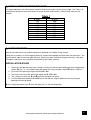
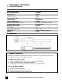
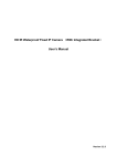
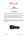
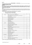
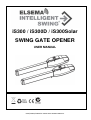
iS300 / iS300D / iS300Solar
SWING GATE OPENER
USER MANUAL
iS300/iS300D/iS300Solar SWING GATE OPENER MANUAL
INDEX
1.1
GENERAL SAFETY PRECAUTION ...........................................................P.1
1.2
INSTALLATION
A. STANDARD INSTALLATION ................................................................P.2
B. INSTALLATION CHECK .......................................................................P.3
C. REAR BRACKET INSTALLATION .......................................................P.4
D. FRONT BRACKET INSTALLATION .....................................................P.5
E. CHECK BRACKET ................................................................................P.5
F. MOTOR FIXING .....................................................................................P.6
G. WIRE CONNECTION .............................................................................P.6
H. EMERGENCY RELEASE ......................................................................P.7
I. MECHANICAL STOPPER ADJUSTMENT .........................................P.7
1.3
TECHNICAL FEATURES
A. TECHNICAL FEATURES .....................................................................P.8
B. DIMENSION ..........................................................................................P.8
1.4
MAINTENANCE ..........................................................................................P.8
iS300/iS300D/iS300Solar SWING GATE OPENER MANUAL
1.1 GENERAL PRECAUTION
WARNING:
This user manual is only for qualified technicians who are specialized in
installations and automations.
1) All installations, electrical connections, adjustments and testing must be
performed only after reading and understanding of all instructions carefully.
2) Before carrying out any installation or maintenance operation, disconnect the
electrical power supply by turning off the mains switch connected upstream
and apply the hazard area notice required by applicable regulations.
3) Make sure the existing structure is up to standard in terms of strength and
stability.
4) When necessary, connect the motorized gate to reliable earth system during
electricity connection phase.
5) Installation requires qualified personnel with mechanical and electrical skills.
6) Keep the automatic controls (remote, push buttons, key selectors.etc) placed
properly and way from children.
7) For replace or repair of motorized system, only original parts must be used.
Any damage caused by inadequate parts and methods will be not claimed to
motor manufacturer.
8) Never operate the drive if you suspect that it might be faulty or will cause
damage to the system.
9) The motors are exclusively designed for gate opening and closing application,
any other usage is deem inappropriate. The manufacturer will not be liable for
any damage resulting from the improper use. Improper usage should void all
warranty, and the user accepts sole responsibility for any risks thereby may
accrue.
10) The system may be operated in proper working order. Always follow the
standard procedures by following the instructions in this installation and
operating manual.
11) Only operate the remote when you have the full view of the gate.
ELSEMA PTY LTD shall not be liable for any injury, damage, or any claim to
any person or property which may result from improper use or installation
of this system.
Please keep this installation manual for future reference.
iS300/iS300D/iS300Solar SWING GATE OPENER MANUAL
1
1.2 STANDARD INSTALLATION
A. STANDARD INSTALLATION
2
iS300/iS300D/iS300Solar SWING GATE OPENER MANUAL
B. CHECKS BEFORE INSTALLATION
Before proceeding with the installation check the following:
1) The maximum gate leaf weight should not exceed the maximum leaf length rating shown in
Graph 1.
2) Check that the motor mounting position on the gate pillar can be done with the measurements
in Figure 1 and Graph 2.
3) Be sure that gate moves freely.
4) There are no obstacles in the moving gate area.
5) Hinges are properly positioned and greased.
6) There should be no friction between the two gate leafs.
7) There should be no friction with the ground while moving the gates.
8) Check that the gate structure is suitable to install automatic gate motors.
Graph 1
iS300/iS300D/iS300Solar SWING GATE OPENER MANUAL
3
C. INSTALLATION OF REAR BRACKET
Step 1 : Calculate the position of the rear bracket by using the details in Figure 1 and Graph 2. This Figure
and Graph establishes dimensions A, B and the maximum opening angle. If your gate is opening 90˚
you can also use values for greater than 90˚ from Graph 2.
Step 2 : Before securing the rear bracket to the pillar check the front bracket can be welded to a solid point
on the gate leaf.
•
•
•
•
Fully close the gate.
Connect the rear and front brackets to the motor.
Hold the rear bracket onto the pillar with the calculated A and B values.
Move the motor in a vertical direction until the fixing zone is in a solid area of the gate leaf for
the front bracket.
Step 3 : Then fix the rear bracket to the pillar.
Figure 1
4
Graph 2
iS300/iS300D/iS300Solar SWING GATE OPENER MANUAL
D. INSTALLATION OF FRONT BRACKET
For proper operation, the front bracket should be fixed so the motor has the correct angle. Use Table 1 to
calculate the location of the front bracket. Also note that the front bracket is 50mm lower than the rear
bracket.
Table 1
A (mm)
120
130
140
150
160
170
180
190
200
E (mm)
580
570
560
550
540
530
520
510
500
E. CHECK BRACKET
Secure the motor to the rear and front bracket as detailed in the Motor Fixing section.
Follow the instructions in the Emergency Release section to disengage the motor from the mechanics. You
should now be able to move the gate manually. Slowly fully open and close the gate manually. If the gate
fully opens and closes the installation of the brackets was done correctly.
INSTALLATION RULES
1. To prevent the operator from over running its maximum and minimum operating limits the operating
stroke, Cu (Cu= A + B) should always be shorter than the available stroke CD which is 350 mm.
2. To achieve 90˚ opening of a gate leaf A + B = Cu
3. To achieve more than 90˚ opening of a gate leaf A + B < Cu
4. The smaller the values for A and B the faster the gates will travel.
5. Limit the difference between A and B to less than 40 mm. Higher difference will vary the gate
opening and closing speed.
B must always be greater than F when the gate leaf is in the closed position
iS300/iS300D/iS300Solar SWING GATE OPENER MANUAL
5
F. MOTOR FIXING
While the motor is disengaged, remove the wire cover and fix the rear bracket with the pin. The
pin will slot into the hole with the threaded side up as shown in no.1. No screw is required to
hold the pin in place. Attach the front bracket to the drive unit with the nut provided as shown
in no.2.
Make sure the iS300 is mounted in a horizontal position, especially in these positions:
1) Gate in “CLOSE” position
2) Gate in “OPEN” position
3) Gate at “45° angle” position
Prior to welding the bracket on the gate leaf( if necessary), cover the gate opener to prevent
damages from sparks.
G. WIRE CONNECTION
To connect the iS300 with the control unit
1
White
Motor (+)
2
Yellow
Motor (-)
Avoid tension in the cable during opening and closing cycles
6
iS300/iS300D/iS300Solar SWING GATE OPENER MANUAL
H. EMERGENCY RELEASE
In case of power failure, slide the lid of the manual release chamber forward. Insert the key and
turn clockwise to unlock, and then turn around the knob to release.
Step1. Slide the lid of the release chamber forward
Step2. Insert the key and turn clockwise into the unlock position
Step3. Then turn the knob clockwise to release the motor.
Make sure the white bar on the knob is on the position opposite to the
triangle indicator.
To restore the automation, simply reverse the above procedure.
I. MECHANICAL STOPPER ADJUSTMENT
To adjust mechanical stoppers, follow the steps below:
Step1. Remove the screws from both sides of the motor cover
Step2. Push the front external tube forward separating it from the motor base
Step3. Release the screw on the mechanical stopper to change the position
* The position of the front and rear mechanical stopper indicates the fully Open/Close positions of the gate.
J. ELECTRICAL CONNECTION
After successful motor installation, refer to the user manual of the control card
for automatic operation setup.
iS300/iS300D/iS300Solar SWING GATE OPENER MANUAL
7
1.3 TECHNICAL FEATURES:
A. Technical Features:
Motor Voltage
24Volts DC motor
Gear Type
Worm gear
Max Absorbed Power
144 Watts
Peak Thrust
3000N
Nominal Thrust
3000N
Stroke Length (CD)
350mm
Power Supply
Nominal Input Power
Maximum Operating Current
Maximum Gate Weight
Maximum Gate Length
Duty Cycle
Operating Temperature
Dimension
Weight
240 Volts AC
2 Amps
5.5 Amps for maximum 10 sec
300 kg per leaf
3 metres
20%
-20°c ~ +50°c
812mm x 123mm x 124mm
6.6 kg
B Dimension:
1.4 MAINTENANCE:
Maintenance should be performed at least every six months. If it is used in high traffic area, a
more regular maintenance should be performed.
Disconnect the power supply:
(1)
(2)
(3)
Clean and lubricate the screws, the pins and the hinge with grease.
Check the fastening points are properly tightened.
Check and make sure that the wire connections are in good condition.
Connect the power supply:
(1)
(2)
(3)
8
Check the power adjustments.
Check the function of the manual release
Check the photocells or other safety device.
iS300/iS300D/iS300Solar SWING GATE OPENER MANUAL
Service History
Date
Maintenance
iS300/iS300D/iS300Solar SWING GATE OPENER MANUAL
Installer
9
Solar kits
Solar panels
Backup batteries
Photo electric beams
Magnetic locks
Wireless keypads
Pre formed loop
Visit www.elsema.com to see our full range
of Gate and Door Automation products
iS300/iS300D/iS300Solar SWING GATE OPENER MANUAL