1
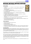
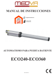
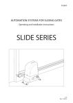
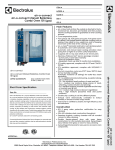
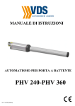
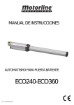
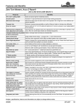
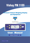
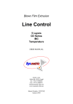
iS320 / iS320D
HYDRAULIC SWING GATE
OPENER
USER MANUAL
iS320/iS320D SWING GATE OPENER MANUAL
INDEX
1.1
GENERAL SAFETY PRECAUTION ..........................................................P.1
1.2
INSTALLATION
A. INSTALLATION CHECK ......................................................................P.2
B. BRACKET MOUNTING DIMENSIONS ................................................P.3
C. INSTALLATION ………………………...................................................P.4
D. HYDRAULIC LOCK …......................................................................... P.6
E. EMERGENCY RELEASE......................................................................P.6
F. BAC & ANTI-WIND SYSTEM................................................................P.7
G. TECHNICAL DATA ..............................................................................P.7
H. KIT CONTENTS …………………………..……......................................P.8
I. DIMENSIONS …………………….…………….......................................P.9
J. ELECTRICAL INSTALLATION ………………......................................P.10
1.3
MAINTENANCE .........................................................................................P.10
iS320/iS320D SWING GATE OPENER MANUAL
1.1 GENERAL PRECAUTION
WARNING:
This user manual is only for qualified technicians who are specialized in
installations and automations.
1) All installations, electrical connections, adjustments and testing must be
performed only after reading and understanding of all instructions carefully.
2) Before carrying out any installation or maintenance operation, disconnect the
electrical power supply by turning off the mains switch connected upstream
and apply the hazard area notice required by applicable regulations.
3) Do not install this equipment in an easily flammable environment. The presence of
inflammable gases or smoke are a serious threat to personal safety.
4) In addition to safety devices it is also necessary to install at least one light signal
as well as a printed notice fixed to the gate.
5) Make sure the existing structure is up to standard in terms of strength and
stability.
6) This equipment must be earthed with a yellow/ green cable, connected to the earth
terminal in the junction box. The safety of this product is only guaranteed if the
equipment is properly earthed.
7) Installation requires qualified personnel with mechanical and electrical skills.
8) Keep the automatic controls (remote, push buttons, key selectors etc.) placed
properly and way from children.
9) For replace or repair of motorized system, only original parts must be used.
Any damage caused by inadequate parts and methods will be not claimed to
motor manufacturer.
10) Never operate the drive if you suspect that it might be faulty or will cause
damage to the system.
11) The motors are exclusively designed for gate opening and closing application,
any other usage is deem inappropriate. The manufacturer will not be liable for
any damage resulting from the improper use. Improper usage should void all
warranty, and the user accepts sole responsibility for any risks thereby may
accrue.
12) The system may be operated in proper working order. Always follow the
standard procedures by following the instructions in this installation and
operating manual.
13) Only operate the remote when you have the full view of the gate.
ELSEMA PTY LTD shall not be liable for any injury, damage, or any claim to any
person or property which may result from improper use or installation of this
system.
Please keep this installation manual for future reference.
iS320/iS320D SWING GATE OPENER MANUAL
1
A. CHECKS BEFORE INSTALLATION
Before proceeding with the installation check the following:
1)
2)
3)
4)
5)
6)
Make sure that the gate moves freely.
There are no obstacles in the moving gate area.
Hinges are properly positioned and greased.
There should be no friction between the two gate leafs.
There should be no friction with the ground while moving the gates.
Check that the gate structure is suitable to install automatic gate motors.
Gate length
Max. 2 Metre
Light gate : 400Kg
iS320 - 110°
Medium gate : 600Kg
iS320 - 110°
Heavy gate : 800Kg
iS320 - 110°
Opening Inwards
2
Max. 4 Metre
iS320 - 95°
iS320 - 95°
Opening Outwards
iS320/iS320D SWING GATE OPENER MANUAL
B. A & B Dimensions
Table 1
Inward Opening
M
85°
90°
95°
100°
105°
110°
115°
A
130
120
110
100
93
85
85
B
125
120
120
120
120
120
115
C
70
70
70
70
70
70
70
Outward Opening
85°
90°
95°
100°
130
120
110
100
120
120
120
120
80
80
80
80
All measurements are from the center of the Hinge and are in millimetres (mm).
In some installations it might not be possible to follow the exact dinemsions in the above table due
to a number of reasons. If this is the situation, please refer to the Graph 1 below for INWARD
opening, A & B dimensions.
Graph 1
3
iS320/iS320D SWING GATE OPENER MANUAL
C. INSTALLATION
1) Check that the motor mounting position on the gate pillar can be done with the measurements
in Table 1 and Graph 1.
2) Fix the pillar support as shown in (Fig.1 Page5) shortening or extending the support according
to the dimensions A and B shown in the (Table1 Page 4). The support should be fixed at a
height where the gate has a sufficiently rigid surface to fix the gate support, bearing in mind
that the gate support will be fixed 15 mm lower than the pillar support. (Fig.1 Page 10).
3) Shorten or lengthen the gate support according to the dimensions for C shown in the table on
page 3. Connect the iS320 opener to the gate support, with the rod completely extended
(Fig.2 Page 5) and with the swivel joint nut fully tightened (Fig.3 Page 5). Once this has been
done use a spirit level (Fig.4 Page 5) to mark the position of the gate support on the gate.
Dismantle the gate support and fix it to the gate using the markings previously made.
4) Mount the motor and unscrew the swivel joint nut three
turns to ensure closure. Attach the security ring and the
safety bolt supplied. (Fig.6 Page 5).
5) Electrical connections: Unscrew the end cover and
connect the terminals according to the following diagram
6) Open the door manually to the desired open position, slide
the collar stopper along the arm (Fig.9 Page 5) up to the
front cover plate, fixing its position with the Allen key. The hydraulic transmission can then be
plugged in and started. Re-position the collar stopper to achieve the desired opening and
closing positions.
7) Once the motor is working correctly the limit valves can be adjusted (Fig.10 Page 5). The limit
valves control the force and are independent in opening (blue limit valve) and closing (red limit
valve) the gate. The screws can be adjusted by turning them a maximum of 45º and should be
adjusted slightly above the minimum, in this way the force of the hydraulic system is reduced
thus increasing safety.
8) The closing buffer can then be adjusted (Fig.11 Page 5), thus avoiding the door banging
closed. To adjust the closing buffer turn the screw a maximum of 10º( If the buffer valve is
completely closed then 15mm of buffering will be lost) .
9) The aluminium arm cover can then be placed back into position (Fig.12 Page 5), followed by
its plastic cover and the end cover.
iS320/iS320D SWING GATE OPENER MANUAL
4
iS320/iS320D SWING GATE OPENER MANUAL
5
D. INSTALLING HYDRAULIC LOCK
When installing locks on hydraulic powered gates it is necessary to consider the type of opening.
The iS320 has 2 different connections for locks which depends on the type of opening.
- Inward opening (Page 2) The lock should be connected to
position 2 (see diagram).
- Outward opening (Page 2) The lock should be connected to
position 1 (see diagram).
*An external lock is required for gates over 1.8m in length.
E. EMERGENCY RELEASE SYSTEM
In an event of power failure, the iS320 can be operated manually. For manual operation, open up the cover
shown in the picture and turn the valve 360° anti clockwise. Now the gate can be moved manually. To
reengage the motor, turn the valve 360° clockwise.
Note: If the valve is not fully open or fully closed, operator will not function properly.
6
iS320/iS320D SWING GATE OPENER MANUAL
F. BAC & ANTI-WIND SYSTEM
The pressure of the gate can be adjusted by turning the Red and Blue valves located underneath
the motors. The pressure can be adjusted while the motors are not running and is independent for
opening cycle and closing cycling.
Red is for the opening cycle and Blue is for the closing cycle. Opening these valve will increase
the pressure and closing will decrease the pressure.
If these valves are slightly opened, they serve as an excellent anti-wind system.
An external lock is required for gates over 1.8m in length.
G. TECHNICAL DATA
Motor Voltage
240 Volts AC
Power
Running Current
Capacitor
Type
Max Pressure
Opening Cycle
Closing Cycle
Compression
Traction
Maximum Gate Leaf Length
Operating Temperature
Dimension
Weight
276 Watts
1.3 Amps
16uF
Hydraulic
50 bar
23 sec
28 sec
0 - 795Kg
0 – 638Kg
4 metres
-20°c ~ +50°c
985mm x 94mm x 88mm
11 kg
iS320/iS320D SWING GATE OPENER MANUAL
7
H. KIT CONTENTS
8
iS320/iS320D SWING GATE OPENER MANUAL
Description
1
iS320
2
Plastic cover
3
Aluminium cover
4
Pillar motor support
5
Gate motor support
6
Motor cables
7
Allen key for pressure adjustment
8
Support plate
9
Setup nuts and bolts
10
End cover for the arm
11
Wire housing
12
Stopper bracket
13
Hinge set with nut
14
Motor support kit
15
Oil refill for iS330
16
16uF Motor start capacitor
17
Hydraulic lock
18
Hydraulic hose
19
Mounting & fittings for hydraulic hose
I. DIMENSIONS
iS320/iS320D SWING GATE OPENER MANUAL
9
J. ELECTRICAL CONNECTION
After successful motor installation, refer to the user manual of the control card
for automatic operation setup.
1.3 MAINTENANCE:
Maintenance should be performed at least every six months. If it is used in high traffic area, a more
regular maintenance should be performed.
Disconnect the power supply:
(1)
(2)
(3)
Clean and lubricate the screws, the pins and the hinge with grease.
Check the fastening points are properly tightened.
Check and make sure that the wire connections are in good condition.
Connect the power supply:
(1)
(2)
(3)
10
Check the power adjustments.
Check the function of the manual release
Check the photocells or other safety device.
iS320/iS320D SWING GATE OPENER MANUAL
Service History
Date
Maintenance
iS320/iS320D SWING GATE OPENER MANUAL
Installer
Domestic/Industrial Sliding Gate Kits
Domestic/Industrial Swing Gate Kits
FOB Remotes
Hydraulic Locks
Magnetic Locks
Wireless Keypads
Pre formed Loop
Visit www.elsema.com to see our full range
of Gate and Door Automation products
iS320/iS320D SWING GATE OPENER MANUAL