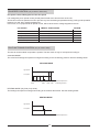
1
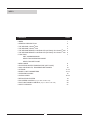
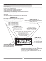
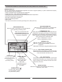
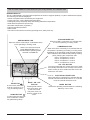
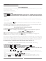
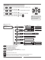
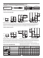
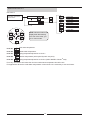
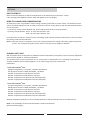
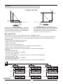
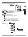
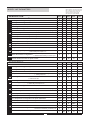
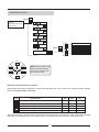
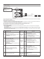
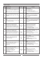
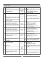
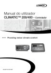
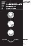
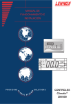
USER MANUAL CONTROLLER Climatic® 200/400 English/07-2006 INDEX CONTENTS PAGE INDEX GENERAL DESCRIPTION THE KEYPAD, Climatic® 200 1 2 3 4 5 6 7 THE KEYPAD, Climatic® 400 THE KEYPAD REMOTE CONTROLLER (OPTION), RC Climatic® 200 THE KEYPAD REMOTE CONTROLLER (OPTION), RC Climatic® 400 FUNCTION UNIT COMMISSIONING SELECTING OPERATING MODE SELECTING SET POINT 8 MENU MODE 9 ADJUSTING WATER TEMPERATURE (SET POINT) 10 ANALOGUE INPUTS, TEMPERATURE PROBES 11-12 OPTIONS 13-14 MODIFY UNIT PARAMETERS 15 OPERATING HOURS 16-18 ALARM CODES 19 DEFROSTING SYSTEM 20 FAN SPEED CONTROL (only for 0091 to 0812 units) 20 FAN FUNCTIONING CONTROL (only for 1003 to 1303 units) SAFETY DEVICES 21 1 GENERAL DESCRIPTION This equipment is an electronic device that controls packaged water cooling systems via air and reversible air/water heat pumps: (EAC/EAR 0251SM to 1804SM). The thermostat allows the following operations: - Unit ON/OFF. - Select system operating mode. - Set point adjustment. - Alarm signal relay. - Display temperature. - Status of the unit alarms. - Possibility of remote ON/OFF. - A remote controller as an option. REGULATION: The control makes the system regulation as follow: - Receives the signals of analogue inputs through the inlet and outlet probe temperature values and the refrigerant piping probe temperature/pression(the probe is placed in the plater/exchanger) two for model Climatic® 400. - Receives digital inputs through the status of low and high pressure switches, flow switch (water flow) status and from electrical protection of fan and compressor. According to the values and status of analogue and digital inputs manages: the output signals; compressor, fan and status of water pump operating, obtaining the regulation of the inlet water temperature to the unit, regulating the speed of the air fan volume, activating the defrost cycle (heat pump units only); output signals water exchange heater, water tank heater, and hot gas valve (all these elements are an option) used to protect the unit, and also activates the alarm codes about, setting pressure switches, flow switch, water flow, and the electrical protection of fan and compressor (see alarm section). - A group of parameters let the control be programmed for each application. The control incorporated in the unit contains the following devices: MODEL Climatic® 200 (1 circuit unit model EAC 0251 to 0812 and EAR 0251 to 0812) MODEL Climatic® 400 (2 circuit unit model EAC 1003 to 1804 and EAR 1003 to 1804) - Keypad: Located in the unit. The keypad provides control of the system. - Fan Control Plate: Located at the electrical box. Allows the fan speed to be varied with respect to the condensing temperature (only for Standard and FP1 units). - Keypad: Located in the unit. - Control Module: Located at the electrical box. This device controls the operation of the unit, allowing the regulation of the system. Keypad located in the unit 1 Fan control plate 2 Keypad located in the unit 1 2 set set on off Climatic® 200 Control Module mode mode on off 3 4 Climatic® 400 Fan control plate OPTION A remote controller is offered as an option. To install this optional remote controller proceed as follow: - Connect exactly as indicated in electrical diagram. - The wire should not exceed 50 m. The three cables for connection from the keypad to the power board must be kept separate from other cables, using an individual cable channel; and use shielded cables, with a cross-section of 1 mm2. Electrical box at the unit Terminal block Remote controller (option) 2 x 1000 * Three-lead shielded cable with a cross-section of 1 mm2 *Connection to be made by customer MAXIMUM LENGTH 50m 2 1 THE KEYPAD INCORPORATED AT THE UNIT, MODEL Climatic® 200 READING DISPLAY This is a 3-digit display, the inlet water temperature is shown in degrees (default), ºC (when shows decimal point). The following can also be displayed: - Values of all parameters controlled by the equipment. - Cooling set point, cooling differential temperature. - Heating set point (heat pump units) and heating differential temperature. - Outlet water temperature (as security). - Inlet water temperature (regulation). - Piping temperature/pression. - Alarm codes. - The status of all machine functions (operating hours, delay time etc). COMPRESSOR LED When this LED is continually lit, it indicates that the compressor is operating (in heating or cooling mode, depending on the operating mode selected); however, when it flashes, this indicates that pausing is taking place, delaying the compressor start. LED 1: Compressor 1 circuit 1 LED 2: Compressor 2 circuit 1 HEATING MODE LED When this LED is continually lit it indicates that the unit is operating in heating mode. MODE / UP BUTTON Selects the operating mode between the following: Stand-by / Cool / Heat In menu mode, this button acts as a scroll up or up key (increasing value). COOLING MODE LED When this LED is continually lit it indicates that the unit is operating in cooling mode. COOLING MODE LED / HEATING MODE LED When none of these two leds COOLING/HEATING are lit, it indicates that the operating mode selected is STAND-BY. DEFROST LED LED ON: The defrosting is in progress. LED OFF: If defrosting is disabled or has been completed. LED BLINK: If timing is in progress (defrost interval). 1 2 mode set on off Climatic® 200 READING DISPLAY ELECTRICAL HEATER LED When this LED is continually lit it indicates that the internal anti-freeze electrical heater is on; if the led is off, the internal anti-freeze is off. MODE - ON / OFF BUTTON Pressing both buttons at the same time, gets to the menu level. They also move one level up or down in the menu. ON - OFF / DOWN BUTTON Turn the unit ON and OFF. Press also once to reset all manually reset alarms not currently active; all the alarm events per hour will also be reset even if the alarms are not active. In menu mode, this key acts as a scroll down or down key (decreasing value). 3 THE KEYPAD INCORPORATED AT THE UNIT, MODEL Climatic® 400 READING DISPLAY This is a 3-digit display, the inlet water temperature is shown in degrees (default), ºC (when shows decimal point). The following can also be displayed: - Values of all parameters controlled by the equipment. - Cooling set point, cooling differential temperature. - Heating set point (heat pump units) and heating differential temperature. - Outlet water temperature (as security). - Inlet water temperature (regulation). - Piping temperature/pression. - Alarm codes. - The status of all machine functions (operating hours, delay time etc). COMPRESSOR LED When this LED is continually lit, it indicates that the compressor is operating (in heating or cooling mode, depending on the operating mode selected); however, when it flashes, this indicates that pausing is taking place, delaying the compressor start. LED 1: Compressor 1 circuit 1 LED 2: Compressor 2 circuit 1 LED 3: Compressor 1 circuit 2 LED 4: Compressor 2 circuit 2 HEATING MODE LED When this LED is continually lit it indicates that the unit is operating in heating mode. MODE / UP BUTTON Selects the operating mode between the following: Stand-by / Cool / Heat In menu mode, this button acts as a scroll up or up key (increasing value). COOLING MODE LED When this LED is continually lit it indicates that the unit is operating in cooling mode. COOLING MODE LED / HEATING MODE LED When none of these two leds COOLING/HEATING are lit, it indicates that the operating mode selected is STAND-BY. 1 2 mode set on off 3 ELECTRICAL HEATER LED When this LED is continually lit it indicates that the internal antifreeze electrical heater is on; if the led is off, the internal antifreeze is off. 4 MODE - ON / OFF BUTTON Pressing both buttons at the same time, gets to the menu level. They also move one level up or down in the menu. Climatic® 400 READING DISPLAY ON - OFF / DOWN BUTTON Turn the unit ON and OFF. Press also once to reset all manually reset alarms not currently active; all the alarm events per hour will also be reset even if the alarms are not active. In menu mode, this key acts as a scroll down or down key (decreasing value). 4 THE KEYPAD REMOTE CONTROLLER (OPTION), MODEL RC Climatic® 200 READING DISPLAY This is a 3-digit display, the inlet water temperature is shown in degrees (default), ºC (when shows decimal point). The following can also be displayed: - Values of all parameters controlled by the equipment. - Cooling set point, cooling differential temperature. - Heating set point (heat pump units) and heating differential temperature. - Outlet water temperature (as security). - Inlet water temperature (regulation). - Piping temperature/pression. - Alarm codes. - The status of all machine functions (operating hours, delay time etc). COOLING MODE LED When this LED is continually lit, it indicates that the unit is operating in cooling mode. HEATING MODE LED When this LED is continually lit, it indicates that the unit is operating in heating mode. COMPRESSOR LED When this LED is continually lit, it indicates that the compressor is operating (in heating or cooling mode, depending on the operating mode selected); however, when it flashes, this indicates that pausing is taking place, delaying the compressor start. LED 1: Compressor 1 circuit 1 LED 2: Compressor 2 circuit 1 When none of these two leds COOLING/HEATING are lit, it indicates that the operating mode selected is STAND-BY. DEFROST LED LED ON: The defrosting is in progress. LED OFF: If defrosting is disabled or has been completed. LED BLINK: If timing is in progress (defrost interval). 2 x 1000 1 MODE ON/OFF ELECTRICAL HEATER LED When this LED is continually lit, it indicates that the internal anti-freeze electrical heater is on; if the led is off, the internal anti-freeze is off. UP BUTTON In menu mode, this button acts as a scroll up or up key (increasing value). MODE - ON / OFF BUTTON Pressing both buttons at the same time, gets to the menu level. They also move one level up or down in the menu. DOWN BUTTON In menu mode, this key acts as a scroll down or down key (decreasing value). ON - OFF BUTTON Turn the unit ON and OFF. Press also once to reset all manually reset alarms not currently active; all the alarm events per hour will also be reset even if the alarms are not active. MODE BUTTON Selects the operating mode between the following: Stand-by / Cool / Heat 5 THE KEYPAD REMOTE CONTROLLER (OPTION), MODEL RC Climatic® 400 READING DISPLAY This is a 3-digit display, the inlet water temperature is shown in degrees (default), ºC (when shows decimal point). The following can also be displayed: - Values of all parameters controlled by the equipment. - Cooling set point, cooling differential temperature. - Heating set point (heat pump units) and heating differential temperature. - Outlet water temperature (as security). - Inlet water temperature (regulation). - Piping temperature/pression. - Alarm codes. - The status of all machine functions (operating hours, delay time etc). COOLING MODE LED When this LED is continually lit, it indicates that the unit is operating in cooling mode. HEATING MODE LED When this LED is continually lit, it indicates that the unit is operating in heating mode. COMPRESSOR LED When this LED is continually lit, it indicates that the compressor is operating (in heating or cooling mode, depending on the operating mode selected); however, when it flashes, this indicates that pausing is taking place, delaying the compressor start. LED 1: Compressor 1 circuit 1 LED 2: Compressor 2 circuit 1 LED 3: Compressor 1 circuit 2 LED 4: Compressor 2 circuit 2 When none of these two leds COOLING/HEATING are lit, it indicates that the operating mode selected is STAND-BY. ON - OFF BUTTON Turn the unit ON and OFF. Press also once to reset all manually reset alarms not currently active; all the alarm events per hour will also be reset even if the alarms are not active. 1 x 100 2 MODE ON/OFF 3 4 ELECTRICAL HEATER LED When this LED is continually lit it indicates that the internal anti-freeze electrical heater is on, if the led is off, the internal anti-freeze is off. UP BUTTON In menu mode, this button acts as a scroll up or up key (increasing value). DOWN BUTTON In menu mode, this key acts as a scroll down or down key (decreasing value). MODE - ON / OFF BUTTON Pressing both buttons at he same time, gets to the menu level. They also move one level up or down in the menu. MODE BUTTON Selects the operating mode between the following: Stand-by / Cool / Heat 6 FUNCTION UNIT COMMISSIONING When all the instructions in the Operating, Service and Installation Manual have been carried out, the unit can be commissioned as follows: POWER SUPPLY TO THE UNIT - Set the general cut-off switch to ON. TURN ON/OFF THE UNIT - Pressing on off button for more than 2 seconds lets you turn ON the unit. The display lights up and shows the inlet water temperature, or an alarm indication, and the different leds on the unit will flash (see page 16 for alarm section). If "E00" is shown, indicates that the unit has been turn off by the remote ON/OFF switch, located between 93 and 94 terminals at the electrical box. If the unit does not incorporate this switch, verify that a link exists between these terminals. - To turn OFF the unit press until water pump stops. on off button for more than 2 seconds. Before disconnecting power supply, wait NOTE: When unit is not going to be operating during long periods of time do not turn off power supply, select the OFF operating mode in order to anti-freeze protection works. SELECTING THE UNIT'S OPERATING MODE The operating mode is always indicated on the display by leds. Pressing the mode button repeatedly you can change the unit operating mode, and select the required one: HEAT COOL STAND BY COOL: The unit is working on cooling mode, the led will light up on the display. HEAT: The unit is working on heating mode, the led will light up on the display (only heat pump units). STAND BY: The unit is working on stand-by, none led will light up. Once cooling or heating mode has been selected, water pump will turn on. If cooling is the unit's operating mode selected and the inlet water temperature exceeds the cooling set point, or if heating mode has been selected and the inlet water temperature drops below the heating set point, there will be a demand for the compressor to start, then the compressor led starts blinking, indicating that the compressor start is delayed due to the compressor recycle timer operation (see page 20); after this the compressor will start and the led is on. SELECTING THE WATER TEMPERATURE OF THE SYSTEM (SET POINT) To modify the set point of the unit follow the steps: - Press the buttons on off and mode simultaneously, the display will show up . - Press the buttons on off and mode again, the display will show up (cooling set point). Pressing the buttons and , the display will show up (heating set point) (only heat pump units). - Once positioned on the set point which should be changed or : press the buttons on off and mode simultaneously and release within 2 seconds, and the display shows up the current set point; and with buttons or may change the set point between maximum and minimum limits. Once the set point has been changed press on off and mode simultaneously. - To get to the main display, press on off and mode simultaneously for more than 2 seconds, the display will show up ; press again on off and mode for more than 2 seconds, and you will be on the main display. 7 MENU MODE Press mode and on off buttons and release within 2 seconds, to enable the user to get to the menu mode mode To move through the menu on this way : on off Press mode and buttons simultaneously and release within 2 seconds. To move through the menu on this way : Press mode and on off buttons simultaneously for more than 2 seconds. To move through the menu on this way To move through the menu on this way , press: , press: mode + + on off on off >2" <2" NOTE: When the leds on the display flash alternatively from one to the other, you are on menu mode. MENU STRUCTURE MAIN DISPLAY It shows: Inlet water temperature Active alarms LEVEL 2 LEVEL 1 SET POINT Probe status LEVEL 3 Cooling set point Set point value cool Heating set point Set point value heat Codes Probe value ----- Active alarms Codes ALARMS ----- PARAMETERS Password value (number 38) PASSWORD Compressor operating hours OPERATING HOURS --- Water pump operating hours Water temperature adjustment menu. Status temperature probes menu: St1: Inlet water temperature. St2: Outlet water temperature. St3 and St6: Piping temperature/pression. St4: Outdoor temperature (with option Dynamic set point). Active alarms Menu. Configuration parameters menu. Password to access to parameters configuration (number); the password is 38. Operating hours resources management (compressor, water pump). 8 Amount of hours Amount of hours SET POINT THERMOSTAT FUNCTION DESCRIPTION LEVEL 1 MAIN DISPLAY It shows: Inlet water temperature Active alarms LEVEL 2 SET POINT LEVEL 3 Cooling set point Set point value Heating set point Set point value See page 7, for adjustment of set point of the system. The water temperature is thermostatically controlled via a set point and a tolerance range (differential). The operation of these parameters is shown in the following diagrams: COOLING OPERATING MODE Step 1 Step 1 Step 1 Step 2 Step 2 Step 3 Step 4 Step 3 c03 Step 2 2xc03 c03 Compresor OFF c03 Compresor ON Set point c03 ºC Set point + Diferencial c03 c05 c03 Set point Units with 1 compressor c03 c05 ºC c03 c05 ºC c05 Set point Set point Units with 2 compressors c03 c05 ºC c05 Units with 3 compressors Units with 4 compressors Operation with one compressor is as shown in the diagram taking into account that the temperature about which the controller takes over is the inlet water temperature. When this temperature exceeds the set point + tolerance range (differential) the compressor starts to produce cool water. When inlet water temperature gets below the set point the compressor stops. For example, when the set point = 11ºC and differential = 2ºC, the compressor stops when inlet water temperature is 11ºC and starts when this temperature exceeds 13ºC. HEATING OPERATING MODE Step 4 Step 3 Step 2 Step 2 Step 3 Step 2 Step 1 Step 1 c04 Step 1 2xc04 c04 Compresor ON c04 Compresor OFF Set point + Diferencial c04 ºC c04 Set point Units with 1 compressor c04 c05 ºC c04 c04 c05 c05 c05 c04 c05 c05 Set point Set point Units with 2 compressors ºC ºC Set point Units with 3 compressors Units with 4 compressors Operation with one compressor is as shown in the diagram taking into account that the temperature about which the controller takes over is also the inlet water temperature. When this temperature gets below the set point - Differential, the compressor starts to produce heat water. When the inlet water temperature exceeds the set point, the compressor stops. For example: when the set point = 41ºC and differential = 2ºC, the compressor stops when the inlet water temperature is 41ºC and starts when this temperature gets below 39ºC. NOTE: The units with 3 compressors and the Low water temperature kit work with 2 steps according to the units with 2 compressors. MAX: Maximum value for the parameter. UNIT: The units of measure used. MIN: Minimum value for the parameter. VAR.: Minimum variation allowed. DEF: The default value, factory set. AFFECTED PARAMETERS Code that appears on the display 1 COMPRESSOR UNIT VALUES 2 COMPRESSOR UNIT VALUES 3/4 COMPRESSOR UNIT VALUES MIN MAX DEF MIN MAX DEF MIN MAX Cooling set point 10 15 11 9 14 10 8 14 9 ºC 0,1 Heating set point 20 43 41 20 43 42 20 43 43 ºC 0,1 0 25,5 2 0 25,5 1.5 0 25,5 1 ºC 0,1 25,5 1.5 0 25,5 1 ºC 0,1 25,5 1.5 0 25,5 1 ºC 0,1 DESCRIPTION Cooling differential temperature Heating differential temperature 0 25,5 2 0 Differential for second compressor --- --- --- 0 9 DEF UNIT VAR. ANALOGUE INPUTS MAIN DISPLAY It shows: Inlet water temperature Active alarms SET POINT Press Press mode Probe value Probe value on off Probe status Probe value Probe value Probe value mode mode + + on off on off >2" <2" NOTE: When the leds on the display flash alternatively from one to the other, you are on menu mode. Probe St1 Inlet water temperature. Probe St2 Outlet water temperature. Probe St3 Piping temperature/pression at circuit 1. Probe St4 Outdoor temperature (with option Dynamic set point). Probe St6 Piping temperature/pression at circuit 2 (ONLY MODEL Climatic® 400). For every unit without anti-freeze the minimum outlet water temperature should be 5ºC. For applications where the outlet water temperature is lower than 5ºC is necessary to use anti-freeze. 10 OPTIONS ON/OFF REMOTE Remove the wire between 93 and 94 terminal block on the electrical box and insert a contact. If the unit stops with ON/OFF Remote, "E00" will appear on the unit display. REMOTE CHANGEOVER SUMMER/WINTER On heat pump units, it is possible to select cooling or heating mode with a remote contact. The ON/OFF remote can be combined with this function in order to control the unit from a long distance, with the Off/Cool/Heat options. To use this option: 1) Connect a remote contact between the 99 and 100 terminal block on the electrical box. 2) Change the parameters: H27=1 for units with Climatic® 200. H49=1 for units with Climatic® 400. From this moment, when the contact is open, the heating mode has been selected, and when the contact is closed, the cooling mode has been selected. Note 1: when this function is enabled, you can only change between the cooling and heating mode through this contact. The change through the remote control or through the unit display is disabled. DYNAMIC SET POINT With this Option which incorporates an additional outdoor temperature probe (St4) to have a Dynamic adjustment to the set point based on ambient temperature. The set point value can be increased to 3ºC on cooling mode, or decreased to 4ºC on heating mode when the external conditions are more advantageous, so an extra energy saving can be achieved. Parameters: - Units with Climatic® 200: H08 St4 configuration= 0 no probe, 3 Outdoor temperature. H31 Dynamic set point enable (0 disabled, 1 enabled). H34 Ext. temperature in cool Dynamic set point. H35 Ext. temperature in heat Dynamic set point. H36 Ext. temperature cool Dynamic set point differential. H37 Ext. temperature heat Dynamic set point differential. - Units with Climatic® 400: H14 St4 configuration= 0 no probe, 3 Outdoor temperature. H50 Dynamic set point enable (0 disabled, 1 enabled). H53 Ext. temperature in cool Dynamic set point. H54 Ext. temperature in heat Dynamic set point. H55 Ext. temperature cool Dynamic set point differential. H56 Ext. temperature heat Dynamic set point differential. Outdoor temperature probe has to be connected between 97 and 98 terminal block on the electrical box. Note 1: On the display, the St4 probe indicates the outdoor temperature. (See the following page.) 11 OPTIONS Set point ºC DYNAMIC SET POINT Set point ºC 42ºC heating set point 12ºC 38ºC 9ºC cooling set point 25ºC 35ºC starting differential Dynamic set point -10ºC outdoor temp. ºC outdoor temp. ºC 6ºC starting differential Dynamic set point 6ºC COOLING MODE When the outdoor temperature exceeds 35ºC, the unit set point is the set value. The Dynamic set point function starts when the temperature is below 35ºC. The set point value increases below 35ºC, so for 25ºC (10ºC differential) the set point is 3ºC more than the set value. 12ºC HEATING MODE (only for heat pump units) When the outdoor temperature is 6ºC the unit set point is the set value. The Dynamic set point function starts when the temperature exceeds 6ºC. The set point value decreases above 6ºC, so for 12ºC (6ºC differential) the set point is 4ºC less than the fixed value. BMS CONNECTION It is possible to connect the unit to a BMS system with a MODBUS protocol. A communication adaptor is installed in the unit. With a GATEWAY, 8 units can be connected. It is possible to achieve a net with 15 GATEWAYS. This net communicates with a BMS system through MODBUS protocol. The interface can: - Select between OFF/STAND-BY/COOL/HEAT. - Modify the cooling and heating set point. - Read the alarm status. - Read all the functioning temperatures. - Read the status of inputs (pressure switches, fluid switch, thermal protection...). - Read the status of outputs (compressor, fan, pump...). - Read the maximum and minimum set point available in cooling and heating mode. Parameters: - Units with Climatic® 200: H26 Serial output configuration 1= ModBus. H44 Family serial address= 0. H45 Device serial address= 1..8 (different for each one connected to the GATEWAY). - Units with Climatic® 400: H48 Serial output configuration 1= ModBus. H65 Family serial address= 0. H66 Device serial address= 1..8 (different for each one connected to the GATEWAY). Gateways KP06 no.1 Adress 10H BA Adress 11H BA Adress 18H BA BA: Bus Adapter EB: Electrical Box KP06 no.2 EB BA Adress 20H EcoLean 1 EB EcoLean 2 EB KP06 no.15 EB Adress F0H BA EcoLean 9 Adress 21H BA Adress 20H BA EB EcoLean 10 EcoLean 8 EB EcoLean 16 12 EB EcoLean 113 Adress F1H BA Adress F8H BA EB EcoLean 114 EB EcoLean 120 MODIFY PARAMETERS MAIN DISPLAY Press mode on off It shows: Inlet water temperature Active alarms Press Press Press mode mode + + on off on off >2" <2" PARAMETERS NOTE: When the leds on the display flash alternatively from one to the other, you are on menu mode. Press mode on off Menu of configuration parameters of the unit. General configuration parameters of the unit (Values (H)). Configuration parameters concerning to compressor (Values (C)). Configuration parameters concerning to fan and defrost control (Values (F)). Configuration parameters concerning to active alarms (Values (A)). Configuration parameters concerning to water pump (Values (P)). Configuration parameters concerning to anti-freeze (Values (r)). Configuration parameters concerning to defrost cycle (Values (d)). To access to parameters modification, a password should be included to the system; this is not necessary if you only want to see the parameters. Press It shows: Inlet water temperature Active alarms mode on off Press Press Press Press Press mode on off PASSWORD Press 13 Insert password (number 38) MODIFY UNIT PARAMETERS DESCRIPTION 1 CIRCUIT UNIT MODEL MAX: Maximum value for the parameter. MIN: Minimum value for the parameter. DEF: The default value, factory set. UNIT: The units of measure used. VAR.: Minimum variation allowed. MIN MAX DEF Climatic® UNIT VAR. 200 Cooling thermal regulator hysteresis Heating thermal regulator hysteresis Steps delta 0 0 0 25.5 25.5 25.5 1.5 1.5 1.5 ºC ºC ºC 0.1 0.1 0.1 St4 configuration 0: no probe / 3: outdoor temp. Serial output configuration Operation mode selection 0: selection by keyboard / 1: selection by digital input 0 0 0 3 1 2 0 0 Num --Num 1 1 1 Dynamic set point enable 0: no enable / 1: enable 0 1 0 --- 1 Ext. temperature in cool Dynamic set point Ext. temperature in heat Dynamic set point -127 -127 127 127 35 6.0 ºC ºC 1 1 Ext. temperature cool Dynamic set point differential -12.7 12.7 -10.0 ºC 0.1 Ext. temperature heat Dynamic set point differential -12.7 12.7 6.0 ºC 0.1 Family serial address 0 14 0 Num 1 Device serial address Compressors activation sequence 0 14 0 Num 1 0 1 0 --- 1 Alarm output polarity 0 1 0 --- 1 Water tank heater configuration: 0: Switched on by the controller 0 1 1 --- 1 Internal antifrost heater set point in heat 1 48 35 ºC 1 UNIT VAR. 0: open relay if the output is on 1: closed relay if the output is on 1: Switched automatically in defrost cycle DESCRIPTION 2 CIRCUITS UNIT MODEL MIN MAX DEF Climatic® 400 Cooling thermal regulator hysteresis 0 25.5 1.5 ºC 0.1 Heating thermal regulator hysteresis 0 25.5 1.5 ºC 0.1 Steps delta 0 25.5 1.5 ºC 0.1 0 1 1 --- 1 0 1 0 --- 1 0: no probe / 3: outdoor temperature 0 3 0 Num 1 0: open relay if the output is on 1: closed relay if the output is on 0 1 0 --- 1 Serial output configuration 0 1 0 --- 1 Operation mode selection 0: selection by keyboard / 1: selection by digital input 0 1 0 --- 1 Dynamic set point enable 0 1 0 --- 1 Ext. temperature in cool Dynamic set point -127 127 35 ºC 1 Ext. temperature in heat Dynamic set point -127 127 6 ºC 1 Ext. temperature cool Dynamic set point differential -50.0 80.0 -10.0 ºC 0.1 Ext. temperature heat Dynamic set point differential -50.0 80.0 6.0 ºC 0.1 Compressors activation Balancing of the circuits St4 configuration Alarm relay polarity sequence 0: depending on operating hours 1: starting sequence 0: saturation of the circuits 1: balanced circuits 0: no enable / 1: enable Family serial address 0 14 0 Num 1 Device serial address 0 14 0 Num 1 0 1 1 --- 1 1 48 35 ºC 1 Water tank heater configuration: 0: Switched on by the controller 1: Switched automatically in defrost cycle Internal antifrost heater set point in heat 14 OPERATING HOURS Press mode on off It shows: Inlet water temperature Active alarms Press Press Press Press Compressor 1 operating hours Press Press Compressor 2 operating hours mode Compressor 3 operating hours on off Compressor 4 operating hours OPERATING HOURS mode mode + + on off on off >2" <2" Water pump operating hours NOTE: When the leds on the display flash alternatively from one to the other, you are on menu mode. Resetting of operating hours counters When display shows the compressor or water pump operating hours, the counters can reset by pressing ON/OFF button and release within 2 seconds. CODE PARAMETERS MIN MAX UNIT Operating hours compressor 1 circuit 1 0 9.99 hrs/khrs Operating hours compressor 2 circuit 1 Operating hours compressor 1 circuit 2 Operating hours compressor 2 circuit 2 0 0 9.99 9.99 hrs/khrs hrs/khrs 0 9.99 hrs/khrs Water pump operating hours 0 9.99 hrs/khrs The display shows the operating hours value without the decimal point up to 999 hours. If the counter has exceeded 999 hours, the operating hours value appears with 2 decimals and the point decimal (1.00=1000 hours). 15 ALARM CODES MENU STRUCTURE MAIN DISPLAY It shows: Inlet water temperature Active alarms LEVEL 1 SET POINT Press Probe status Press Press mode on off LEVEL 2 Active alarms Codes ALARMS ----- The unit self-protects through safety devices; when any of these safety devices detect an anomaly, this is shown in the display in order to advise the operator. The activation of an alarm brings about: - The display of the alarm code beginning with the letter E and follows a number; if more than one alarm will be activated, the alarm shown would be the one with the lowest numerical value. - In some cases, it can block some of the outputs, stopping the unit, depending on the type of alarm. E00: This indication is not an alarm; it indicates that unit is turn off from ON /OFF remote. VIS (Visualization): It indicates the type of alarm shown on the display. RE (Reset): Type of reset: AUT: AUTOMATIC RESET: Some alarms are automatically reset. When the cause is no longer present, they disappear from the display. MAN: MANUAL RESET: Press ON/OFF button and release within 2 seconds. If the alarm conditions have been removed, the instrument returns to the normal operation and the alarm relay is de-energized. If on the other hand, the alarm conditions persist, then call for technical service. VIS. DESCRIPTION EFFECT RE E01 High pressure switch alarm. Circuit 1 This alarm may indicate the following problems: compressors MAN - High pressure switch protection. stop - Stopped fan. E02 Low pressure switch alarm. This alarm may indicate the following problems: - Low amount of refrigerant. Circuit 1 - Low water flow in cooling cycle. compressors AUTO/ - Blocked coil in heating cycle. MAN stop - Stopped fan. After two automatic resets in one hour, it comes to be a manual reset. E03 Compressor thermal protection alarm: - Compressor thermal protection open. - Faulty power supply. Compressor 1 MAN circuit 1 stops E04 Fan thermal protection alarm. Circuit 1 Fan and circuit 1 MAN compressors stop 16 ACTION Reset and check: Coil is clean and not blocked. Water flow on the heating cycle. Check fan protection. Condenser air temperature is very high. Check refrigerant charge. Reset and check: Coil is clean and not blocked. Water flow on the cooling cycle. Check fuses of the fan. Evaporation air temperature is very low. Check refrigerant charge. Reset and check: Check refrigerant charge. Check the refrigerant circuit is not blocked. Check connections and protections. Check power supply. Reset and check: - Fan - Check connections and protections. ALARM CODES VIS. DESCRIPTION E05 Anti-freeze alarm. It indicates the outlet water temperature is lower than +3ºC (it kit low water temperature is not fitted). After 1 automatic reset, it comes to be a manual reset. E06 Outlet water temperature probe alarm (St2). Outlet water temperature probe open or without connecting. E07 Refrigerant piping temperature probe (St3) alarm. Refrigerant piping temperature or pression probe open or without connecting. EFFECT Unit stops (*) Unit stops Unit stops RE ACTION Reset and check: Check the water filter. AUTO/ Check water flow. Check that the water pump is MAN connected to power supply of the unit. Check: Connection of outlet water temperature probe (St2) (see electrical diagram), AUTO check continuity and change the faulty component. Check: Connection of refrigerant piping temperature/ pression probe (St3) (see electrical diagram), AUTO check continuity and change the faulty component. Check: Working of high pressure switch. Coil is clean and not blocked. AUTO Water flow on the heating cycle. Check fan protection. Condenser air temperature is very high. Check refrigerant charge. E11 High pressure / high temperature alarm. It is activated when refrigerant piping temperature/pression probe (St3) detects a temperature higher than 70ºC/45bar and the high pressure switch has not been activated. E12 Low pressure / low temperature alarm. It is activated when refrigerant piping temperature/pression probe (St3) detects a temperature lower than -30ºC/ 2bar and the low pressure switch has not been activated. E13 Compressor 2 thermal protection alarm: - Compressor thermal protection open. - Faulty power supply. E21 High pressure switch alarm, circuit 2. This alarm may indicate the following problems: - High pressure switch protection. - Stopped fan. E22 Low pressure switch alarm, circuit 2. Check: This alarm may indicate the following problems: Coil is clean and not blocked. - Low amount of refrigerant. Circuit 2 Water flow on the cooling cycle. - Low water flow in cooling cycle. AUTO/ compressors Check fan protection. - Blocked coil in heating cycle. MAN stop Evaporation air temperature is very low. - Stopped fan. Check refrigerant charge. After two automatic resets in one hour, it comes to be a manual reset. Circuit 1 compressors stop Circuit 1 compressors stop Compressor 2 circuit 1 stops Circuit 2 compressors stop (*) Unit stops except water pump. 17 Check low pressure switch working. Coil is clean and not blocked. Check water flow on the cooling cycle. AUTO Check fan protection. Evaporation air temperature is very low. Check refrigerant charge. MAN MAN Reset and check: Check refrigerant charge. Check the refrigerant circuit is not blocked. Check connections and protections. Check power supply. Check: Coil is clean and not blocked. Water flow on the heating cycle. Check fan protection. Condenser air temperature is very high. Check refrigerant charge. ALARM CODES VIS. E23 DESCRIPTION EFFECT RE Compressor 1 circuit 2 thermal protection alarm: Compressor 1 - Compressor thermal protection open. circuit 2 MAN - Faulty power supply. stops E24 Fan thermal protection alarm. Circuit 2 fan and circuit 2 compressors stop ACTION Check: Check refrigerant charge. Check the refrigerant circuit is not blocked. Check connections and protections. Check power supply. Reset and check: MAN - Fan - Check connections and protections. E27 Refrigerant piping temperature probe alarm (St6) circuit 2. It may indicate: - Refrigerant piping temperature probe open or without connecting. E31 High pressure / high temperature alarm. It is activated when refrigerant piping temperature/ pression probe (St6) detects a temperature higher than 70ºC/45bar and the high pressure switch has not been activated. E32 Check low pressure switch working. Low pressure / low temperature alarm. Coil is clean and not blocked. It is activated when refrigerant piping Circuit 2 Check water flow on the cooling cycle. temperature/ pression probe (St6) detects a compressors AUTO Check fan protection. temperature lower than -30ºC/2bar and the low stop Evaporation air temperature is very low. pressure switch has not been activated. Check refrigerant charge. E33 Compressor 4 thermal protection alarm. - Compressor thermal protection open. - Faulty power supply. E40 Inlet water temperature probe alarm (St1). It may indicate: - Inlet water temperature probe open or without connecting. Unit stops AUTO Connection of refrigerant piping temperature/ pression probe (St6) (see electrical diagram), check continuity and change the faulty component. Check: Working of high pressure switch. Circuit 2 Coil is clean and not blocked. compressors AUTO Water flow on the heating cycle. stop Check fan protection. Condenser air temperature is very high. Check refrigerant charge. Compressor 2 circuit 2 MAN stops Check refrigerant charge. Check the refrigerant circuit is not blocked. Check connections and protections. Check power supply. Unit stops Check connection of inlet water temperature AUTO probe (St1) (see electrical diagram), check continuity and change the faulty component. E41 It indicates low water flow in the unit. Unit stops (*) Check water circuit is not blocked. AUTO Check water filter. Check water pump operation. E42 St4 probe error. Unit stops Check the St4 probe connection or cancel AUTO Dynamic set point if the unit does not incorporate St4 probe. E45 Alarm of configuration error. Unit stops AUTO It may indicate that the terminal is broken. Unit stops Check connection of inlet water temperature AUTO probe (St1) (see electrical diagram), check the continuity and change the faulty component Water flow switch alarm. E46 High inlet water temperature. It indicates: Inlet water temperature probe detects temperatures higher than 90ºC during more than one minute. (*) Unit stops except water pump. 18 DESCRIPTION OF THE DEFROSTING SYSTEM The defrosting process is activated during heating mode in heat pump units, when the outside temperature is low and the outdoor coil could become frozen. To melt the ice the defrosting function will switch the unit to cooling operation for a short period. During defrosting mode the low pressure is at minimum level, consequently the pressure switch is disabled in this mode. The manufacturer uses default control settings which apply to most installations. The set parameters determine the following: INITIAL DEFROSTING TEMPERATURE The defrosting cycle begins when outdoor probe pression is below 5,7 bar. END DEFROSTING CYCLE The defrosting cycle ends when outdoor probe pression of the refrigerating pipe reaches 35 bar. DELAY BETWEEN TWO DEFROSTING REQUESTS Time between two defrosting cycles is calculated from the end of one to the beginning of next, and it is 30 minutes. This defines the time during which the initial defrosting pression must be maintained. When this time has elapsed, the unit starts to defrost. If the initial defrosting increases before this time has elapsed, the timer would block and it would only start to count when the temperature returns below the starting defrosting pression. This pausing prevents the unit from carrying out continual defrosting patterns. MAXIMUM DEFROSTING DURATION It is the maximum defrosting time. This defines the maximum period if the temperature has not exceeded a set value. This timing prevents too long defrosting cycles. The maximum defrosting time will be 5 minutes. DEFROSTING CYCLE SEQUENCE: When the defrosting cycle starts the compressor stops, the four-way valve reverses 30 seconds and after 30 seconds, the compressor starts. This cycle ends when the outside exchanger probe detects the final defrosting pression or exceeds a safety interval. When the defrosting cycle has finished, the compressor stops 30 seconds. Then the four-way valve reverses and 30 seconds later, the compressor starts again in heating mode generating again warm water more efficiently due to the absence of frost. 19 FAN SPEED CONTROL (only for 0091 to 0812 units) Fan speed control: Management of the fan speed It is managed by a fan speed control printed plate located at the electrical box of the unit. The function of the fan speed control is to prevent very low condensing temperatures during cooling mode operation between 0ºC and 46ºC outside temperatures. In this case, it is a proportional fan speed control, which varies the fan voltage supplied to the fan. FAN STAGES AMBIENT TEMPERATURE FAN RPM Fan stops Ambient temperature below +5ºC Minimum fan speed Ambient temperature between +5ºC and +20ºC Fan regulation Ambient temperature between +20ºC and +30ºC Silent fan speed Ambient temperature between +30ºC and +35ºC Maximum fan speed Ambient temperature over +35ºC 0 350 350 to 750 750 900 FAN FUNCTIONING CONTROL (only for 1003 to 1804) The fans for these models incorporate 2 speeds. The fans work on high or low speed according to: COOLING MODE: The on/off and low/high fan speed is managed according to the condensing pressure. See the drawing below: COOLING MODE High speed Low speed 0ºC 15ºC 30ºC 35ºC Outside temperature ºC 22bar 28bar 30bar 37bar Condensing pressure HEATING MODE (only heat pump units): The low/high fan speed is managed according to the ambient thermostat. See the drawing below: HEATING MODE High speed Low speed -10ºC +7ºC Outside temperature ºC 20 SAFETY DEVICES The units contain various safety devices to avoid damage to the unit due to very low water temperatures. 1.- Anti-freeze protection. This protection is activated by the control of the unit when the outlet water temperature probe (St2), located inside the water exchanger, measures +5ºC and deactivates when the outlet water temperature probe reaches to +6ºC again. When the protection is activated occurs as follow: - If the unit is on STAND-BY as the operating mode: the water pump goes on, the same happens with electrical heater of water exchanger and electrical heater of water tank (if included). DO NOT TURN OFF THE POWER TO THE UNIT. WHEN THE POWER IS OFF THE ANTI FREEZE PROTECTION WILL NOT OPERATE. - If the unit is operating on cooling mode: feeds the electrical heater of water tank, the electrical heater of the water exchanger, and activates the hot gas injection valve (if the unit incorporates these options). - If the unit is operating on heating mode: feeds the electrical heater of water tank and the electrical heater of the water exchanger (if the unit incorporates these options). 2.- Low water temperature alarm. This alarm activates when the outlet water temperature probe (St2) measures a value of +3ºC. As a consequence, the unit stops. The alarm could be reset when outlet water temperature reaches +8 ºC. 3.- Compressor start delay. There is a start to start anti cycle time of 5 minutes between starts compressor starts and a further delay between compressor stop to start of 5 minutes (maximum number of starts is 12 per hour). 4.- Compressor crankcase heaters. It is located around the compressor. This protection is activated when the unit is stopped in order to keep the compressor oil on suitable conditions and to avoid refrigerant condensing inside the compressor. DO NOT TURN OFF THE POWER TO THE UNIT. WHEN THE POWER IS OFF THE CRANKCASE HEATER PROTECTION WILL NOT OPERATE. 5.- Water pump start delay. In both heating and cooling modes the compressors start 4 minutes after the water pump has started in order to stabilize the water system. DO NOT TURN OFF THE POWER TO THE UNIT. WHEN THE POWER IS OFF THE WATER PUMP START DELAY PROTECTION WILL NOT OPERATE. 21 22 www.lennoxeurope.com BELGIUM, LUXEMBOURG : CZECH REPUBLIC : FRANCE : GERMANY : IRELAND : NETHERLANDS : POLAND : PORTUGAL : RUSSIA : SLOVAKIA : SPAIN : UKRAINE : UNITED KINGDOM : OTHER COUNTRIES : COD: MUL35E-0506 07-2006 LENNOX BENELUX N.V./S.A. www.lennoxbelgium.com LENNOX JANKA a.s. www.janka.cz LENNOX FRANCE www.lennoxfrance.com LENNOX DEUTSCHLAND GmbH www.lennoxdeutschland.com LENNOX IRELAND www.lennoxireland.com LENNOX BENELUX B.V. www.lennoxbenelux.com LENNOX POLSKA Sp. z o. o. www.lennoxpolska.com LENNOX PORTUGAL Lda. www.lennoxportugal.com LENNOX DISTRIBUTION MOSCOW www.lennoxrussia.com LENNOX SLOVENSKO s.r.o. www.lennoxdistribution.com LENNOX REFAC S.A. www.lennoxspain.com LENNOX DISTRIBUTION KIEV www.lennoxrussia.com LENNOX UK www.lennoxuk.com LENNOX DISTRIBUTION www.lennoxdistribution.com Due to Lennox's ongoing commitment to quality, Specifications, Ratings and Dimensions subject to change without notice and without incurring liability. Improper installation, adjustment, alteration, service or maintenance can cause property damage or personal injury. Installation and service must be performed by a qualified installer and servicing agency.