1
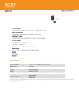
Users Manual
The Hero I Robot
Scott Robarts
Carson Upton
Keith Cardiff
Mar 15/02
1
Table of contents
1. Introduction
2. Sensor Systems Check
2.1 Testing the Head Sensor Board
2.2 Testing the Scanning Infrared Sensor Board
3. Remote Control
3.1 ON/OFF & Mode Select
3.2 Mode 1: Body
3.3 Mode 2: Arm
3.4 Changing the Remote Battery
4. Checking the Fuses
4.1 Removing the Case
4.2 Power Supply Fuses
4.3 Interior Fuses
5. Keypad and LCD
6. Operating System
6.1 Using the operating System
6.2 Running Software
6.3 Loading New Software onto the PC104
6.4 Shutting down the PC104
7. Charging the Hero
8. Troubleshooting
9. Conclusion
2
1. Introduction
In this manual, you will learn the basics of operating and downloading code to the new
version of the Hero I Robot.
In general, the Hero has two modes: Autonomous and Remote Mode. In Autonomous
mode, the Hero will drive about on its own, navigating according to sensor signals it
receives. In Remote mode, control of both the arm and drive functions are transferred to
the user. Simple Reset and Power Down functions can be implemented at a later time.
Each section in this manual describes the basics of what’s necessary to operate the Hero.
Various sensor checks, remote tests, and simple status updates on the Hero’s onboard
LCD are described below.
For basic remote operation, refer to the Remote Control Section(3).
2. Sensor Systems Check
There are two sensor packages on the Hero. The first is located on the top of the robot
above the two speakers (head sensor board). The second is located on the front panel
over the main drive wheel. Both run constant tests to make sure the sensors are working.
You can verify that all sensors are working by going through these simple steps.
2.1 Testing the Head Sensor Board
2.1.1 Removing Head Cover
Place the robot so the speakers on the head face you. Slide off the head
cover so that the head sensor board is visible.
2.1.2 ON/OFF
Turn on the Hero. The main power switch is located on the rear of
the robot on the bottom. The Green LED will light if the power is on.
If this light does not turn on, refer to Checking the fuses.
3
2.1.3 Sonar
You should immediately notice a clicking or ticking sound. This is the
sonar pulsing system. Place your hand in front of the gold sonar disk
mounted on the left side of the head relative to the speakers. When
your hand is about 5 inches in front of the disk the left most LED on the
head sensor board will light up. It should be off unless there is an object
within about 25 inches of the front of the Hero (or the direction the
sonar disk is facing).
2.1.4 Light
Next, we will test the light sensor. The light sensor is located
between the two round holes under the head sensor and is quite
small. It looks like a silver disk with a red line through it. Cover it up
and watch the middle light go off and then on. The Light should
otherwise be on. If the light is off when you are not blocking the light,
try shinning a flash light on it to get it to turn on.
2.1.5 Motion
The last sensor is the motion sensor. You may have noticed the right
most light going on and off. This is the motion sensor LED and it has
been picking up your movement. The light turns on when it senses
motion. Pass your hand in front of it and it will turn on then off after a
short time.
2.2 Testing the Scanning Infrared Sensor Board
2.2.1 Infrared scanner
Turn the robot so the main drive wheel faces you. This is the front of
the Hero and has the scanning infrared sensor mounted near the
bottom of the case. The sensor will be sweeping back and forth in a 180
degree arc. The red LED should light whenever an object is detected
within about 40cm(16inches) of the sensor in the direction the sensor is
pointing. The light should otherwise be off.
2.2.2 Resetting all sensors
If one or more of these sensors does not work try resetting the boards
by pushing the small push-button switch on the board that has the
malfunctioning sensor. The switch for the bottom sensor board is behind
the case. Be careful when removing the case as there are wires running
4
from the panel to the main body of the robot. The switch that resets the
infrared scanner board is on the board that is connected via the blue
cable to the front case board.
3. Remote Control
This tutorial outlines all the arm and drive functions of the Hero I in remote control
mode. Follow these simple procedures to learn the basics of control.
To select Remote Control Mode either turn the remote on (which will override onboard
computer commands) or select it via the keypad.
Once in Remote Control Mode, follow these simple steps and the General Remote
Diagram at the end of the section.
3.1.1 ON/OFF
Ensure that the Hero is turned on. Refer to section 2.1.2 for ON/OFF
instructions.
Turn on the Remote. The ON/OFF switch is located at the top of the remote
on the right side. Pull it towards you to turn it on. The Green Power light
should light up when the power is on.
See General Diagram for switch location (at end of section).
3.1.2 Mode Select
Select the Mode. The Hero I remote has two modes and each execute the
toggle switch and dials differently. These modes are selected by the two way
“Function” switch on the front of the remote.
See General Diagram for switch location (at end of section).
3.2 Mode 1: Body
This mode moves the Hero around on the floor. The dial select switch on the left at
the top of the remote has no effect in this mode. Ensure that the steering is centered
or you will not get full travel in both directions. Simply grab the wheel and move it to
the center then press the red motor control board reset switch located on the top
left of the robots largest circuit board.
3.2.1 Direction
Switch the Upper dial on front of the remote to the desired direction. This is
5
indicated in blue at the top of the remote. The right three positions on the
remote make the Hero go forward, while the left three positions make it go
backwards.
See General Diagram for switch location (at end of section).
3.2.2 Motion
The actual motion of the Hero is controlled by the trigger. Depress the trigger
and the Hero should drive in the direction selected. The trigger switch is old and
the electrical connections are poor. Do not depress the trigger all the way or
the Hero will simply convulse on the floor. The Hero is very top heavy and will
roll over if it is turned while going down hill (this was determined through hours
of rigorous testing on a steeply graded wheelchair ramp). Try not to roll the
Hero as it may not survive! Despite its slowness, the Hero also makes quite a
potent battering ram. Try to avoid this as it is not all that sturdy. It would not
last very long as a ‘Battle Bot’.
See General Diagram for switch location (at end of section).
3.2.3 Steering
Steer the Hero by toggling the Motion switch on the front of the remote. Right
turns right and left turns left when you are standing behind the robot. Looking
at the front of the robot means that the steering is reversed. Remember that the
steering does not self center and you will therefore have to steer out of turns to
go straight again or turn the other direction.
See General Diagram for switch location (at end of section).
Take time to familiarize yourself with the drive functions of the Hero as they
will help greatly when maneuvering to pick up objects.
3.3 Mode 2: Arm
This mode controls all the arm & head functions on the Hero.
Select the mode as described in Section 3.1.2.
3.3.1 Function Select
Each arm function is selected via the main switch dial at the top of the
controller. Turn the switch to the far right to select the gripper, for example.
We will use the gripper as the example for this tutorial. All the functions are
more or less the same and you will have to experiment to find out what goes
6
which direction. At this point, make sure the left switch on the top of the
remote is in the off position or furthest away from you. This position selects
the toggle left/right switch and not the aluminum dial on the right of the remote.
Available Functions:
Wrist Pivot
Wrist Rotate
Gripper
Arm Extend
Shoulder Rotate
Head Rotate(does not work very well)
See General Diagram for switch location(at end of section)
3.3.2 Toggle Select
Make sure the left switch on the top of the remote is in the off position or
pushed away from you. Use the toggle switch on the front of the remote to
open and close the gripper. This toggle switch can be used to control all the arm
functions.
3.3.3 Setting the zero position
Pull the trigger while toggle is selected (3.2) to set the zero position. This
means that if, for whatever reason, the selected function encounters resistance
during its movement and cannot move, you can reset it so the control board
microcontroller knows where it is. When the robot is turned on, it interprets the
position of each function as its zero position. You will need to set the zero point
to get full movement out of the function. In the case of the gripper, for
example, the zero point is fully closed. If you try to pick up an object and close
the gripper on it, it will interpret this as its zero position when the object is
removed. You will have to re-zero the function by pulling the trigger (this will
close the gripper all the way).
See General Diagram for switch location (at end of section).
3.3.4 Dial Select
Rotate the aluminum dial on the side of the remote as far as it will go
counterclockwise. Do not force it. It should rotate smoothly.
See General Diagram for Dial location (at end of section).
Now toggle the left switch on the top of the remote towards you. This
activates the aluminum dial as opposed to the toggle switch as the positioning
system. Make sure the gripper function is selected for this tutorial. All the arm
7
functions are moveable with the dial. Rotate the dial and you should see the
gripper open and close accordingly.
If another function(such as the shoulder rotate) is selected, the dial may not
have enough rotation to do a get the full travel out of the function. Use the
on/off switch for the dial (left switch on the top of the remote) to reset the zero
position on the remote. Whenever the dial is switched on, that will be the zero
point as far as the remote is concerned. When you get the end of travel for the
dial and need more travel out of the selected function, turn the dial off, rotate the
dial to the other extreme and then turn it back on again. This will give you the
added necessary travel on the aluminum dial. The zero point for the remote
dial is not the same as the zero point for the robot functions. To this end,
you cannot initialize the selected function by pulling the trigger. You will have
to switch back to toggle mode to set the zero point on the robot (3.3).
3.4 Changing the Remote Battery
The battery in the remote should last quite a long time. In the event that the remote
does not work or the Power LED becomes dim, the battery should be changed. The
remote requires a standard 9 Volt battery, available at any drug, grocery, or hardware
store.
3.4.1 Removing the Cover
On the left side of the remote, there are four fastening screws. Use a flat head
screwdriver to remove the screws and slide off the left half of the remote.
3.4.2 Removing the Battery
Slide out the two metal plates that have the main dial and all the switches
attached. Be sure to note how the plates slide into the slots. Remove the
battery by unclipping it and replace it with the new one.
3.4.3 Reassembling the Remote
Slide the metal plates back into their respective slots. Be careful not to cross
them over as the two remote halves will not fit back together. Now slide the
two remote halves back together. This may be difficult but be patient.
Smashing the remote on the floor will not help. Replace the screws and turn
the remote on to ensure that the power light comes on.
General Remote Diagram
8
All robot functions are accessible by remote.
4. Checking the Fuses
The Hero has two sets of fuses. One set is are 3A (AGC 3) for the main computer
and imbedded microcontrollers (logic) and the other are 4A (AGC 4) for the main and
arm drive motors. Under normal circumstances, the fuses won’t blow. This is because
the Hero’s new design draws considerably less power than the old design. In the event
that some sort of short occurs, the fuses will blow before any circuitry is damaged.
4.1 Removing the case
Remove the case as per the old Hero I user manual. It is very simple and could be
accomplished by child.
4.2 Power Supply Fuses
9
The Power supply is located on the front of the Hero above the main drive wheel.
There are two fuses on it: One slow blow for the Logic and another for the motors.
You can either inspect the fuses visually or test them with a continuity tester.
4.3 Interior Fuses
Open the rear hatch on the Hero. Inside on the bottom, there a fast blow logic and a
fast blow main drive fuse.
5. Keypad and LCD
The keypad on the Hero will be implemented in future. Commands such as shut down for
the PC104 could easily be implemented. The basis is there but the code has simply not
been added due to time constraints.
Again, the LCD displays limited text but can easily be expended upon in the future. It
currently shows a startup message and the status and of Transmit/Receive signals
between the PC104 and the master PIC microcontroller.
6. Operating System
The Hero runs Slackware Linux as its operating system. This area of the user manual
will deal with getting the auto-navigate mode working.
In the current version of the robot we have not yet implemented functionality to allow the
auto-navigate software to run automatically.
These instructions begin with an explanation of the using the remote log-in capabilities of
the PC104 computer, which is the brains of the robot.
6.1 Using the Operating system
6.1.1 Attach a null-modem cable from COM1 of the PC104 computer to a host
computer which the user can control.
6.1.2 Start-up a terminal program such as Hyperterminal in Windows or Minicom in
Linux.
6.1.3 Configure the settings of the terminal program to 19200 baud, eight-bits, no
parity, one stop bit.
6.1.4 With a null-modem cable attached to COM1 of the PC104 computer, turn on the
robot. The PC104 computer will start booting Linux.
10
6.1.5 The booting process will take approximately three to five minutes. At
completion of the booting process, a prompt will appear on your screen in the
form “LinuxMZ>”.
6.1.6 You will now be prompted to log-in. Enter guest as the username and guest
as the password. You will now be logged in to the PC104 via remote login.
6.2 Running Software
In order to start the software running the user needs to perform the following steps.
6.2.1 Remotely log in to the PC104 computer as detailed above.
6.2.2 At this point you should become “superuser” (root) by typing in “su” at the
prompt. The computer will then prompt you for a password. This is blank so
simply press enter.
6.2.3 When this is completed you should navigate to /home/guest where the autonavigate software is located.
6.2.4 Once you are in /home/guest to run the software simply type ./iomgr, but be
careful, once the software is run the robot will be running on its own, so be
careful not to drive it off a table or something similar.
6.2.5 Once the program is running you can disconnect the host computer from COM1
and let the robot run on its own.
6.3 Loading New Software onto the PC104
6.3.1 Remotely login to the PC104 computer as detailed above.
6.3.2 Become “superuser” (root) of the system by typing “su” at the command
prompt, then simply hit enter when prompted for a password.
6.3.3 When this is complete type “lrz” at the command prompt. The computer should
then tell you that it is waiting for a file to be transferred.
6.3.4 Next, if using Hyperterminal, go to “transfer” then select “send file” from the
toolbar.
6.3.5 In the “send file” dialog, make sure z-modem is the selected protocol. Navigate
to the file that you wish to transfer, and click “send”.
11
6.3.6 The file will now be sent to the PC104.
6.4 Shutting Down the PC104
6.4.1 Again, remotely log-in to the PC104 computer as detailed above.
6.4.2 You should be able to observe debugging messages being generated by the
computer when you are correctly logged into the computer.
6.4.3 At this point you should type control-c or control-z to stop the program from
running.
Note: There is no compiler installed on the PC104 computer because of memory
space restrictions. All programs must be compiled on another host computer running
the same or a similar operating system as the PC104 computer. The compiled
executables can then be moved to the PC104 computer and executed there.
7. Charging the Hero
The Hero has four 6 volt onboard batteries and therefore needs charging every now
and then. The new system is considerably more efficient than the old one but still will
require charging on a periodic basis. If the PC104 central computer does not boot
up or shuts down unexpectedly, it is likely that the batteries require charging.
7.1 Charging
7.1.1 Plug the charger in to the wall.
7.1.2 Plug the gray cord into the plug on the back of the Hero, located under the
ON/OFF switch.
7.1.3 Turn on the power to the charger and both lights should light up. If only the
main power light comes on, something on the Hero isn’t working.
7.1.4 The Charge light will become dim when the Hero is finished charging.
8. Troubleshooting
The new version of the Hero is quite complex in some ways yet very simple in others.
It is not to say that the average non-technical person is incapable of troubleshooting
the
Hero, but there are simply too many things that can go wrong. Anything from
software bugs (that are few and far between) to motor or RF noise can cause undesired
operation.
12
Turning the Hero off then back on again will fix most of the software glitches by
resetting everything.
If all else fails, the designers can be contacted:
Sensor Systems: Carson Upton [email protected]
Central Processing: Scott Robarts [email protected]
Motor & RF Control: Keith Cardiff [email protected]
9. Conclusion
The Hero can be a fun toy and can be used in many situations. It has a variety of
functions accessible by the remote and is quite enjoyable. It also has some very
interesting autonavigate functions. Be careful as this robot as it was designed when
Microprocessors where thought of as fast when they had a clock speed of 8MHz. The
Hero is not all that robust!
are
As you may have noticed, the head does not rotate. This is because of square ball
bearings that were popular in the early 1980’s when the Hero was conceived. There
several other quirks that this robot has that will eventually make themselves apparent.
None of them, however, will result in damage to the Hero or its users.
The Hero is lots of fun and makes a great learner kit. Kids and Adults alike love it and
even pets can have a blast! Enjoy!
13