1
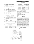
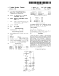
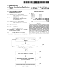
US007203553B2
(12)
(54)
(75)
(73)
United States Patent
(10) Patent N0.:
Fulton et al.
(45) Date of Patent:
US 7,203,553 B2
Apr. 10, 2007
METHODS AND STRUCTURES FOR
4,937,419 A
6/1990 Kolodziej
UTILIZING A MEMORY DEVICE FOR A PLC
5,485,590 A
5,636,357 A
1/ 1996 Hyatt et al.
6/1997 Weiner
Inventors: Temple Luke Fulton, EliZabethton, TN
(US); William H Johnson, Johnson
City, TN (US); Mark Steven Boggs,
5,659,705 A
5,727,170 A
5,765,000 A
8/1997 McNutt et al.
3/1998 Mitchell
6/1998 Mitchell
Johnson City, TN (US); Steven Michael
5,801,942 A *
9/1998 Nixon et al. ................ .. 700/83
Hausman, Johnson City, TN (US)
5,923,903 A * 7/1999 AlvareZ-Escurra et al.
710/62
5,991,510 A
11/1999 Beaulieu
6,473,749 B1* 10/2002 Smith et a1. ................. .. 707/2
Assigneei Siemens Energy & Automation, I110,
Alpharetta, GA (US)
6,826,432 B2*
11/2004 Beck et al. ................. .. 700/18
2001/0034728 Al*
(*) Nome?
31111160110 any (3115312111119; the 371m 5411;;
patent 1s exten e
or a Juste
10/2001
2003/0100958 A1*
McBride et al. ............. .. 707/1
5/2003 Cachat et al. ............... .. 700/18
un er
U.S.C. 154(b) by 343 days.
OTHER PUBLICATIONS
(21) Appl. N0.: 10/685,819
XP-002314619i“C0ntr0l Systems C7iPLC and OP in one
(22)
Filed;
Oct 15, 2003
device”iSiemens Simatic C7 Product Brief, Sep. 2002, pp. l-l2.
XP-002314620iSiemens Simatic HMIi“Pr0T00l How to con?g
(65)
Prior Publication Data
ure graphics-based units” User Manual, Release Dec. 2001, pp.
i-8-8, appendix and index.
US 2004/0133753 A1
Jul. 8, 2004
* cited by examiner
(60)
Related US‘ Application Data
Provisional application No. 60/436,252, ?led on Dec.
Primary ExamineriThomas K Pham
23, 2002, provisional application No. 60/436,249,
(57)
ABSTRACT
?led on Dec. 23, 2002.
Certain exemplary embodiments can provide a method for
(51)
Int. Cl.
(52)
us. Cl. ........................... ..
G05B 11/01
_
_
f1. .
@0060
1212141:
_
700/18; 710/13; 710/23
700/ 18,
700/25’ 23’ 707/103 R’ 103 Z’ 711/115’
_
710/13’ 23
See apphcanon ?le for Complete Search hlstory'
(56)
t d t
‘111mg a nmjlmory Ca .1‘. ge collmeclf
(58) Field of Classi?cation Search ..............
_
11d
(2006.01)
References Cited
1 .
_
.
.
p
I? a
’
e
1.218111: “1:853:38
p
.
ty
compr1s1ng. prov1d1ng the memory cartrldge, the memory
Cartridge housing a memory module’ and providing to the
memory cartridge a project ?le. The project ?le can com
prise a user program, a recipe comprising a plurality of input
values, each input value from the plurality of input values
corresponding to a process variable, and a structure of a data
log ?le stored separately from the data log ?le.
U.S. PATENT DOCUMENTS
4,281,392 A
PLC th
23 Claims, 9 Drawing Sheets
7/1981 Grants
1200
1600
1500
l 700
1400
1300
1800
U.S. Patent
Apr. 10, 2007
Sheet 1 0f 9
US 7,203,553 B2
1000
U
1100
1200
1600
1500
1700
1400
1300
1800
Fig. 1
U.S. Patent
Apr. 10, 2007
Sheet 2 0f 9
US 7,203,553 B2
2000
2100
2200
2300
2400
2500
2600
Fig. 2
U.S. Patent
Apr. 10, 2007
Sheet 3 0f 9
US 7,203,553 B2
3000
Locate a beginning memory
segment on the memory
device for a project ?le to be
written
3100
Provide a project ?le to the
memory device that can
comprise a user program, a
recipe, a structure of a data
log stored separately from
the data log, a structure of
the recipe stored separately
from the recipe, and a
support document
Fig. 3
3200
U.S. Patent
Apr. 10, 2007
Sheet 4 of 9
US 7,203,553 B2
4000
\’
Receive a user request for
information storable on a
memory device
4050
l
Allow a user to select a
language for the display of
information
4100
1
Receive a user input
corresponding to a selected
language
4200
l
Locate information in the
memory device
4300
l
Provide information in the
language selected by the user
Fig. 4
4400
U.S. Patent
Apr. 10, 2007
Sheet 5 of 9
US 7,203,553 B2
5000
Provide ?rst identifying
stamp to data log record
5100
l
Allow user to select
alternative second
identifying stamp for data
log record
5200
l
Receive user input
corresponding to selected
identifying stamp for data
log record
5300
Provide second identifying
stamp to data log record
5400
Fig. 5
U.S. Patent
Apr. 10, 2007
Sheet 6 of 9
US 7,203,553 B2
6000
Provide ?rst setting not to
erase a data log from
memory device after a read
operation
6100
Allow user to select optional
input corresponding to
second setting to erase or not
to erase data log from
memory device after read
operation
6200
Read data log ?le on
memory device and erase
data log from memory
device
Fig. 6
6300
U.S. Patent
Apr. 10, 2007
Sheet 7 of 9
US 7,203,553 B2
7000
Allow user to select
elements of project ?le for
storage
7100
Receive user input
corresponding to selections
of elements of project ?le for
storage
7200
Responsive to user input
selecting elements of project
?le, write project ?le to
memory device
Fig. 7
7300
U.S. Patent
Apr. 10, 2007
Sheet 8 0f 9
US 7,203,553 B2
8000
Locate ?rst head marker
\
indicative of beginning
memory segment for data
log record to be written
8100
l
Write data log record to at
least beginning memory
segment
8200
i
Change ?rst head marker
re?ective of data log record
written at beginning memory
segment
8300
l
Check head marker for
uniqueness and delete
duplicates using checksum
technique
8400
i
Read data log record on the
memory device responsive
to separately stored data log
structure
Fig. 8
8500
U.S. Patent
Apr. 10, 2007
US 7,203,553 B2
Sheet 9 0f 9
9000
H0
9500
Memory
9300
Instructions
9400
Processor
9200
Network Interface
9100
Fig. 9
US 7,203,553 B2
1
2
METHODS AND STRUCTURES FOR
UTILIZING A MEMORY DEVICE FOR A PLC
is a?ixed to the robot drive, the robot automatically has the
information regarding both arm design and system layout,
which will help avoid collisions and provide a starting point
for the ?ne teaching of the transfer stations. Additionally, the
CROSS-REFERENCES TO RELATED
APPLICATIONS
?ne location parameters for each transfer station may be
stored in the Key when the robot is installed. Thus, the Key
This application claims priority to, and incorporates by
will contain all the information needed to make a robot
unique to a unique system, and when a robot drive is
reference herein in its entirety, pending US. Provisional
Patent Application Ser. No. 60/436,252 ?led Dec. 23, 2002,
and pending US. Provisional Patent Application Ser. No.
60/436,249 ?led Dec. 23, 2002.
replaced, by a?ixing the original Key to the new robot or
nearby, it will assume all of the parameters of the initial
robot.” See Abstract.
US. Pat. No. 4,937,419 (KolodZiej) allegedly cites “[a]
BACKGROUND
(PLC’s) can be supplied with a memory device for storage.
The memory device, which can be a memory cartridge, is
most often an electronically erasable programmable read
programmable weld and machine controller for use in con
trolling a welding machine. The controller includes a central
processing unit containing a stored control program con
nected to a memory which operates both the welding opera
tion of the machine as well as the operation of the machine
only memory (EEPROM) device. Common methods of
using the memory cartridge include the storage of PLC
various operational states as well as a data entry and display
Commercially available programmable logic controllers
itself. The controller receives inputs from the machine in its
20
con?guration and programming information.
US. Pat. No. 5,727,170 (Mitchell) allegedly cites: “[t]he
PLC has a user con?gurable protocol port attached thereto.
Brie?y stated, at the PLC communication port or as a result
of a user program or I/O event, a special ?ag bit may be set
25
which thereby allows the communication port to be acti
vated. This is done by the ?ag bit causing an interrupt to
unit and a current monitor of the welding operation which
generates outputs through a heat controlled output to acti
vate a ?ring circuit to control the welding operation. Back
up of the memory program may be attained through an
accessory port to a memory back-up storage unit.” See
Abstract.
SUMMARY
occur in the PLC user program which allows a user to
communicate with a user speci?ed protocol scheme rather
than the normal communication/programming protocol
30
when this special bit is not set.” See Abstract.
memory cartridge comprising a plurality of memory seg
US. Pat. No. 5,485,590 (Hyatt) allegedly cites: “[a]
ments. The method can comprise a plurality of activities
module interfaces a programmable controller to several
serial communication networks over which data may be
exchanged according to different protocols. A module has a
central controller and a separate port circuit for each of the
35
values, each input value from the plurality of input values
port microprocessor have access for the exchange of data.
corresponding to a process variable, and a structure of a data
40
programmable controller. A removable memory cartridge
45
stored in the module de?ning which program is to be
transferred from the memory cartridge into the shared
memory of each port circuit. Protocol parameter con?gura
50
munication protocol used by the program.” See Abstract.
US. Pat. No. 5,991,510 (Beaulieu) allegedly cites “A
FIG. 1 is a block diagram of an exemplary embodiment of
a system 1000;
FIG. 2 is a block diagram of an exemplary embodiment of
a data structure 2000;
FIG. 3 is a ?owchart of an exemplary embodiment of a
robot drive has operating and con?guration parameters at an
installation location stored in an easily removable storage
device on the drive, or nearby, so that special data, such as
The invention and its wide variety of potential embodi
ments will be more readily understood through the following
detailed description, with reference to the accompanying
drawings in which:
tion inquiries are stored for each program so that the user can
be queried to select values for the parameters of the com
log ?le stored separately from the data log ?le.
BRIEF DESCRIPTION OF THE DRAWINGS
stores a plurality of programs for execution by the port
microprocessors to exchange data over the networks using
different communication protocols. Con?guration data is
comprising: providing the memory cartridge, the memory
cartridge housing a memory module, and providing to the
memory cartridge a project ?le. The project ?le can com
prise a user program, a recipe comprising a plurality of input
networks. Each port circuit includes a microprocessor and a
shared memory to which both the central controller and the
The central controller transfers data from the shared memo
ries to a module output coupled to other components of the
Certain exemplary embodiments can provide a method for
utiliZing a memory cartridge connected to a PLC, the
method 3000;
55
FIG. 4 is a ?owchart of an exemplary embodiment of a
that associated with arm design and system layout, including
method 4000;
taught stations, can remain associated with the drive and
installation whereby the drive system can be installed or
replaced in minimal time since the storage device does not
method 5000;
need reprogramming. This removable storage device, in the
FIG. 5 is a ?owchart of an exemplary embodiment of a
FIG. 6 is a ?owchart of an exemplary embodiment of a
60
form of a static memory or Master Key, e.g., a Dallas Key
or E Prom or the like, may be a?ixed to the robot body or
off board nearby, and may store arm design parameters,
programmed while on the robot body or off-line, and
becomes a unique part structured for manufacturing with
respect to the arm set design. Further, nominal system layout
parameters can be prestored in the Key, and when this Key
method 6000;
FIG. 7 is a ?owchart of an exemplary embodiment of a
method 7000;
FIG. 8 is a ?owchart of an exemplary embodiment of a
65
method 8000; and
FIG. 9 is a block diagram of an exemplary embodiment of
an information device 9000.
US 7,203,553 B2
3
4
DETAILED DESCRIPTION
an optical media, an optical disk, a compact disk, a CD, a
digital versatile disk, a DVD, and/or a raid array, etc. The
As used herein, an I/O device can comprise any sensory
oriented input and/ or output device, such as an audio, visual,
memory can be coupled to a processor and can store
tactile (including temperature, pressure, pain, texture, etc.),
olfactory, and/or taste-oriented device, including, for
example, a monitor, display, keyboard, keypad, touchpad,
ing to an embodiment disclosed herein. Memory 9300 can
be adaptable to store instructions 9400.
Instructions 9400 can comprise a plurality of instructions
Written in a machine readable language. Instructions 9400
can be adaptable to process information When executed by
processor 9200. In an operative embodiment, information
instructions adapted for execution by the processor accord
pointing device, microphone, speaker, video camera, cam
era, scanner, and/or printer, potentially including a port to
Which an I/O device can be attached or connected.
As used herein, render means made perceptible to a
used by processor 9200 using instructions 9400 can provide
information to and/or be modi?ed by the processing opera
tion.
human, for example as data, commands, text, graphics,
audio, video, animation, and/or hyperlinks, etc., such as via
any visual and/or audio means, such as via a display, a
Information device 9000 can further comprise an I/O
device 9500. U0 device 9500 can be adaptable to alloW
information device 9000 to communicate directly and/or
indirectly With other information devices and/or users.
FIG. 1 is a block diagram of an exemplary embodiment of
a system 1000. As illustrated, system 1000 can comprise a
monitor, electric paper, an ocular implant, a speaker, a
cochlear implant, etc.
As used herein, an information device can be any general
purpose and/ or special purpose computer, such as a personal
computer, Workstation, server, minicomputer, mainframe,
supercomputer, computer terminal, laptop, Wearable com
puter, and/or Personal Digital Assistant (PDA), mobile ter
20
1200. System 1000 can comprise a machine and/or process
minal, Bluetooth device, communicator, “smart” phone
monitorable and/or controllable by PLC 1200. System 1000
can further comprise hardWare and/or softWare adaptable to
(such as a Handspring Treo-like device), messaging service
(e.g., Blackberry) receiver, pager, facsimile, cellular tele
phone, a traditional telephone, telephonic device, a pro
grammed microprocessor or microcontroller and/or periph
eral integrated circuit elements, an ASIC or other integrated
alloW a user to communicate With PLC 1200. PLC 1200 can
25
process. For example, PLC 1200 can monitor and/ or control
30
device on Which resides a ?nite state machine capable of
implementing at least a portion of a method, structure,
and/or or graphical user interface described herein may be
used as an information device. An information device can
include Well-knoWn components such as one or more net 35
Work interfaces, one or more processors, one or more
an alarms indicator, relay, sensor, another controller, and/or
a motion device, such as a motion controller, such as a
stepper motor controller, a servo controller, an actuator
controller, etc.; a motion drive, such as a stepper drive, servo
drive, etc.; and/or an actuator, such as a stepper motor,
servomotor, linear motor, motor, ball screW, servo valve,
hydraulic actuator, pneumatic valve, etc.
PLC 1200 can include a central processing unit (CPU) via
memories containing instructions, and/or one or more input/
output (I/O) devices, etc.
FIG. 9 is a block diagram of an exemplary embodiment of
an information device 9000. Information device 9000 can 40
comprise a netWork interface 9100. NetWork interface
device 9100 can comprise a telephone, a cellular phone, a
cellular modem, a telephone data modem, a fax modem, a
Wireless transceiver, an ethemet card, a cable modem, a
digital subscriber line interface, a bridge, a hub, a router, or
be a commercially purchased PLC. Alternatively, PLC 1200
can be an information device. PLC 1200 can be used to
monitor and/or control a process, such as an industrial
circuit, a hardWare electronic logic circuit such as a discrete
element circuit, and/or a programmable logic device such as
a PLD, PLA, FPGA, or PAL, or the like, etc. In general any
controller, such as a programmable logic controller (PLC)
45
Which instructions are processed and appropriate control
signals determined. PLC 1200 can further comprise and/or
be coupled to an input-output (I/O) device. The U0 device
can render information obtained from PLC 1200. The user
also can interact With PLC 1200 via the I/O device. As used
herein interact means receiving alerts or noti?cations, revis
ing or sWitching programs, examining control algorithms,
and/or modifying graphics displays, etc.
A memory device, such as a memory cartridge 1100 can
other similar device. Information device 9000 can be con
be couplable to PLC 1200, either directly or via a netWork.
In certain embodiments, memory cartridge 1100 can be
insertable into PLC 1200 and/ or directly connectable to PLC
nectable directly and/or indirectly to other information
devices via netWork interface 9100.
Information device 9000 can further comprise a processor
9200. Processor 9200 can be a central processor, a local 50 1200. The memory device can be non-volatile memory,
volatile memory, ROM, random access memory, ?ash
processor, a remote processor, parallel processors, and/or
distributed processors, etc. The processor can be a general
memory, magnetic media, a hard disk, a ?oppy disk, a
magnetic tape, an optical media, an optical disk, a CD, a
purpose microprocessor, such the Pentium III series of
DVD, and/or a raid array, etc. The memory device can
microprocessors manufactured by the Intel Corporation of
Santa Clara, Calif. In another embodiment, the processor
can be an Application Speci?c Integrated Circuit (ASIC) or
a Field Programmable Gate Array (FPGA) that has been
designed to implement in its hardWare and/or ?rmWare at
least a part of an embodiment disclosed herein. Processor
9200 can make information device 9000 adaptable to per
55
CPU.
In an exemplary embodiment, PLC 1200 can be couplable
to a user interface device 1300 via a netWork 1600. NetWork
1600 can be a public, private, circuit-sWitched, packet
60
ring, LAN, WAN, Internet, intranet, Wireless, Wi-Fi, Blue
Tooth, Airport, 802.1la, 802.1lb, 802.11g, and/or any
Information device 9000 can further comprise a memory
9300. Memory 9300 can comprise any device capable of
storing analog or digital information, for example, a non
volatile memory,
Random Access
sWitched, virtual, radio, telephone, cellular, cable, DSL,
satellite, microWave, AC poWer, tWisted pair, ethernet, token
form according to a plurality of instructions.
volatile memory,
provide storage for instructions or data usable by the PLC’s
equivalents thereof, etc.
Memory, RAM, Read Only Memory, ROM, ?ash memory,
Via user interface device 1300, the user can interact With
PLC 1200. User interface device 1300 can be an information
magnetic media, a hard disk, a ?oppy disk, a magnetic tape,
device. For example, via user interface device 1300, the user
65
US 7,203,553 B2
5
6
can monitor a process, connectable to and/or controllable by
PLC 1200. The user also can interact with PLC 1200 via user
variable can be used to monitor and/or control a process via
a PLC. Recipe 2300 can comprise values for settings such
as: machine speed, machine siZe, product type, product
interface device 1300.
Via network 1600, PLC 1200 can be further couplable to
a process element 1400. Process element 1400 can comprise
composition, product siZe, product labeling, package type,
package siZe, package labeling, a pressure, a temperature,
and/or any other relevant process parameter. Recipe 2300
a machine tool, a robot, a chemical reactor, a stove, a
can be storable in project ?le 2100. Recipe 2300 can be
communicable to provide settings to program 2200 in order
to render a product makable and/or a process operable using
the PLC. Alternatively, recipe 2300 can be communicable to
a different processing device and/or software to provide
settings to render a product makable and/or process oper
able.
furnace, an assembly machine, a packaging machine, and/or
piece of conveying equipment, etc. In an operative embodi
ment, process element 1400 can be controlled, in?uenced,
and/or monitored via PLC 1200.
The PLC can be further communicable with the user via
network interface device 1500. Network interface device
1500 can be a telephone, a cellular phone, a modem, a
Information indicative of the data log structure 2400 can
cellular modem, a telephone data modem, a fax modem, a
wireless transceiver, an ethemet card, a cable modem, a
digital subscriber line interface, a bridge, a hub, a router, or
other similar device. Network interface device 1500 can be
adaptable to allow the user to communicate with PLC 1200
while located remotely from the PLC 1200. Via a network
interface device 1500, network 1600 can be further cou
comprise a symbolic representation of how a data log ?le is
formatted for storage and retrieval. Information indicative of
the data log ?le structure 2400 can be storable in project ?le
2100. Information indicative of the data log ?le structure
2400 can comprise a series of values and/or characters
20
plable to a peripheral network 1700. Peripheral network
1700 can be a public, private, circuit-switched, packet
log structure 2400 can be storable on the memory cartridge
switched, virtual, radio, telephone, cellular, cable, DSL,
or on another memory device. Information indicative of the
data log ?le structure 2400 can be adaptable to render the
satellite, microwave, AC power, twisted pair, ethernet, token
ring, LAN, WAN, Internet, intranet, wireless, Wi-Fi, Blue
Tooth, Airport, 802.1la, 802.1lb, 802.11g, and/or any
correlatable to structural characteristics of the data log ?le.
The data log ?le and/or the information indicative of the data
25
data log ?le machine-storable and/or machine-readable.
Information indicative of the data log ?le structure 2400 can
be storable separately from the data log ?le.
equivalents thereof, etc. etc.
Information indicative of the recipe structure 2500 can
Peripheral network 1700 can be further connectable to a
remote user interface device 1800. Remote user interface
comprise a symbolic representation of how the recipe is
device 1800 can be an information device comprising an I/O 30 formatted for storage and retrieval. Information indicative of
device. In an operative embodiment, peripheral network
1700 can be adapted to allow the user to interact with PLC
1200. Peripheral network 1700 can allow the user to interact
with PLC 1200 from a location hundreds or even thousands
of miles away from PLC 1200. Peripheral network 1700 can
35
be usable to enhance availability and reduce programming,
managerial, and/or maintenance costs attributable to PLC
1200 and/or the monitoring and/or control of process ele
able separately from the recipe.
40
Support document 2600 can comprise a textual and/or
visual representation of information assimilatable to
45
hardware components related to the PLC, software compo
nents related to the PLC, and/or the controlled process, etc.
Support document 2600 can be storable in project ?le 2100.
In an exemplary embodiment, support document 2600 can
ment 1400. Process element 1400 can be one of a plurality
of process elements.
FIG. 2 is a block diagram of an exemplary embodiment of
a data structure 2000. An exemplary embodiment of data
structure 2000 can comprise a project ?le 2100. Project ?le
improve understanding of the PLC, the memory cartridge,
2100 can be storable on a memory device, such as the
memory cartridge. Project ?le 2100 can comprise a program
2200, a recipe 2300, information indicative of a data log ?le
structure 2400, information indicative of a recipe structure
2500, and/or a support document 2600, etc. Data log ?le
structure 2400 can be stored separately from a correspond
ing data log ?le, which can be stored on any memory device.
Recipe structure 2500 can be stored separately from a
corresponding recipe 2300. Project ?le 2100, and/or one or
more elements thereof, can be adaptable to allow the PLC to
monitor and/or control a process element.
Program 2200 can comprise a set of machine-readable
instructions. Program 2200 can be transferable to the PLC.
Program 2200 can be executable on the PLC. Program 2200
can be storable in project ?le 2100. In an operative embodi
ment, program 2200 can be adapted and/or adaptable to
facilitate the performance of tasks by the PLC such as
the recipe structure 2500 can be storable in project ?le 2100.
Information indicative of the recipe structure 2500 can
comprise a series of values and/or characters correlatable to
structural characteristics of the recipe. Information indica
tive of the recipe structure 2500 can be adaptable to render
the recipe machine-storable and/ or machine-readable. Infor
mation indicative of the recipe structure 2500 can be stor
be reviewable by the user at the user interface device in
order to facilitate understanding and/ or modifying the PLC,
hardware related to the PLC, software related to the PLC, the
50
process, the project ?le, the data log ?le, information indica
tive of the structure of the data log ?le, the recipe, and/or
information indicative of the structure of the recipe, etc.
Alternatively, support document 2600 can be rendered to the
user via an I/O device connectable to an information device.
FIG. 3 is a ?owchart of an exemplary embodiment of a
55
method 3000 for using the memory device. At activity 3100,
a beginning memory segment on the memory cartridge can
be located where the project ?le or any component thereof
can be read from and/or written. Alternatively, the beginning
60
memory segment can be located on the memory device. In
an operative embodiment, the project ?le can occupy a
displaying a process ?ow, transferring information, storing
single memory segment. Alternatively, in an operative
information, processing information, prompting a user for
input, controlling a process variable, and/or reporting a
embodiment, the project ?le can occupy a plurality of
memory segments. At activity 3200, the project ?le can be
process output, etc.
Recipe 2300 can comprise at least one of a plurality of
provided to the memory cartridge. Alternatively, the project
input values, each input value from the plurality of input
?le can be provided to the memory device. Providing the
project ?le to the memory device can allow information
values corresponding to a process variable. Each process
contained in the project ?le to be subsequently transferred to
65
US 7,203,553 B2
7
8
the PLC. For example, in case of a power failure erasing
volatile memory in the PLC, certain information erased from
volatile memory can be restorable from the project ?le
stored in the memory device.
At activity 5300, a user input corresponding to a selection
of the second identifying stamp can be received from the
selection device. The second identifying stamp can improve
the user’s ability to analyZe the process log record. Alter
natively, the second identifying stamp can reduce storage
space requirements for a data log record by providing a
smaller second identifying stamp as compared to the ?rst
FIG. 4 is a ?owchart of an exemplary embodiment of a
method 4000 for using the memory device. At activity 4050,
the user can request to obtain (e.g., view, hear, have ren
dered, and/or obtain access to) information stored and/or
identifying stamp.
At activity 5400, the selected second identifying stamp
storable on a memory device. The information can comprise
programming code, programming code documentation, sup
can be provided to the memory device responsive to the user
port documentation pertaining to hardware and/or software
relatable to the PLC, process data, recipe code, and/ or recipe
input. In an operative embodiment providing the second
identifying stamp to the memory device can supply infor
information, one or more data logs, etc. The user can
mation to the user, when the user subsequently analyZes the
potentially improve monitoring, control, and/or manage
data log record, information within the second identifying
stamp can be adaptable to improve the e?iciency of analyZ
ing, sorting, and/or otherwise processing information in the
data log record.
ment of the PLC and/or at least one process element with the
obtained information.
At activity 4100, the user can be prompted to select a
language for rendering the information from a plurality of
FIG. 6 is a ?owchart of an exemplary embodiment of a
language choices. The user can be allowed to provide a
selection corresponding to a selected language. The user can
method 6000 for using the memory device. At activity 6100,
20
be allowed to make a selection on an I/O device connectable
a ?rst setting can be provided corresponding to an instruc
tion to erase or to not erase the data log from the memory
to an information device. Language choices can comprise
device after the data log is read. The instruction to erase or
any language, such as English, German, French, Italian,
not erase the data log ?le subsequent to reading the data log
Spanish, and/or Chinese, etc. The user can select the lan
guage by providing a user input corresponding to a selected
?le can allow a user to more effectively manage data storage
25
and retrieval on the memory device. Erasing the data log ?le
language.
can provide an assurance that no data log record on the
At activity 4200, the user input can be received corre
sponding to a selected language. The user input can be
memory device has been previously read.
At activity 6200, the user can be allowed to select a
received as a result of a user interacting with an I/O device
second setting corresponding to an instruction to erase or to
connected to an information device. The user input can 30 not erase the data log from the memory device after the data
improve communicability of information to and/or from the
PLC via transferring the information in a language favored
log is read. The second setting can provide instructions
contrary to the ?rst setting. Providing the second setting can
and/ or better understood by the user.
At activity 4300, the information can be located on the
memory device. The information can be located by the
actions of the PLC or any information device directly and/or
allow the user improved control over data storage resources.
At activity 6300, the data log can be read from the
35
erased from the memory device responsive to the user input.
Reading the data log can allow the user to transfer infor
indirectly connectable to the PLC. Locating the information
can facilitate communications between the user and the
PLC.
At activity 4400, the information can be provided to the
user responsive to the user input corresponding to the
selected language. The information can be provided, in the
selected language, to the user interface device. Alternatively,
the information can be provided, in the selected language, to
any l/O device and/or any information device.
memory device. The data log can then be erased or not
40
mation for additional processing and/or storage responsive
to needs to analyZe and/or improve the monitoring, control,
and/or reporting of the process element controllable by the
PLC.
FIG. 7 is a ?owchart of an exemplary embodiment of a
method 7000 for using the memory device. At activity 7100,
the user can be prompted allowed to select elements of a
45
FIG. 5 is a ?owchart of an exemplary embodiment of a
project ?le for storage on the memory device. The selectable
elements can comprise the project ?le, the program, the
method 5000 for using the memory device. At activity 5100,
recipe, information indicative of the recipe structure, infor
a ?rst identifying stamp can be provided for a data log
record. The ?rst identifying stamp can comprise a calendar
date and/ or a clock time associated with requesting, collect
mation indicative of the data log ?le structure stored sepa
rately from the data log ?le, and/or support documentation
50
ing, receiving, and/or recording the data log record. Alter
natively, the ?rst identifying stamp can relate to a process
unit, such as a machine, instrument, and/or device, etc.,
associated with a data log record. For example, the ?rst
identifying stamp can be a process unit identi?er, such as a
pertaining to the process, the PLC, hardware related to the
PLC, and/or software related to the PLC.
At activity 7200, a user input corresponding to an option
to store at least one project ?le element can be received from
the selection device. Providing the user with storage options
55
can allow the user to customiZe a storage plan to suit unique
machine number, a sensor number, and/ or an actuator num
system requirements taking into consideration such factors
ber, etc. In an operative embodiment, the process identifying
stamp can assist the user in analyZing and categoriZing data
as: other means for storing the project ?le, the siZe of the
memory cartridge, the amount of process data collected for
log records.
At activity 5200, the PLC can allow the user to select a
storage in the data log ?le, the frequency of storing process
60
data collected for storage in the data log ?le, the number of
recipes storable in the memory device, and/or the amount
and/or content of support documentation available, etc.
At activity 7300, project ?le elements can be written to
the memory device responsive to the user input. The project
65
?le elements can be written beginning at a vacant memory
second identifying stamp from a plurality of choices. Iden
tifying stamp choices can comprise various date and/or time
elements comprising a year, a month, a day, a day of week,
an hour, a time Zone, a minute, a second and/or a portion of
a second, etc. Alternatively, the second identifying stamp
can comprise various numbers and/or symbols relatable to
the process unit.
segment. Alternatively, project ?le elements can overwrite a
previously stored project ?le.
US 7,203,553 B2
9
10
responsive to the data log structure. Information indicative
of the data log structure can be stored separately in the
FIG. 8 is a ?owchart of an exemplary embodiment of a
method 8000 for using the memory cartridge. At activity
memory device.
8100, a ?rst head marker, indicative of a beginning memory
segment for a data log record to be Written, can be located
Still other embodiments Will become readily apparent to
those skilled in this art from reading the above-recited
on the memory device. The data log record can be of a siZe
storable on a single memory segment. Alternatively, the data
detailed description and draWings of certain exemplary
log record can be of a siZe storable on a plurality of memory
embodiments. It should be understood that numerous varia
segments. Memory segments usable for data log storage can
be spatially and/or logically contiguous, and/or can be
tions, modi?cations, and additional embodiments are pos
Writable sequentially.
At activity 8200, the data log record, Which can comprise
and embodiments are to be regarded as being Within the
sible, and accordingly, all such variations, modi?cations,
spirit and scope of the appended claims. For example,
regardless of the content of any portion (e.g., title, section,
a second head marker, can be Written to at least the begin
ning memory segment. The data log record can be Written on
at least one vacant memory segment. Alternatively, the data
log record can overwrite at least one memory segment used
by an older data log record. The second head marker can
abstract, draWing ?gure, etc.) of this application, unless
clearly speci?ed to the contrary, there is no requirement for
any particular described or illustrated activity or element,
any particular sequence of such activities, or any particular
interrelationship of such elements. Moreover, any activity
can be repeated, any activity can be performed by multiple
contain information re?ective of a location of a next
memory segment for storage of a next data log record. In an
exemplary embodiment, the data log ?le can be Written in a
logically circular buffer. The logically circular buffer can be
entities, and/or any element can be duplicated. Further, any
20
characterized by data log records Written to contiguous
memory segments, the buffer commencing at a beginning
memory segment. The logically circular buffer can be fur
ther characterized by the Writing of the next data log record
at the beginning of the buffer When the buffer is full. The
next data log record can overWrite an oldest data log record
Written in the logically circular buffer. For example, if the
buffer is full, the next data log record to be Written can be
vary. Accordingly, the descriptions and draWings are to be
regarded as illustrative in nature, and not as restrictive.
25
What is claimed is:
1. A machine-readable project ?le, encoded in a machine
readable medium, related to a process controllable via a
PLC, comprising:
a user program for controlling the process;
Written at the beginning of the buffer, thereby overWriting
the data log record that Was previously at the beginning of
the buffer. The logically circular buffer can comprise a
circular bu?'er Wherein memory segments are physically
contiguous to each other.
At activity 8300, the ?rst head marker can be changed to
a record marker re?ective of the data log record Written in
activity or element can be excluded, the sequence of activi
ties can vary, and/or the interrelationship of elements can
30
a recipe comprising a plurality of input values, each input
value from the plurality of input values corresponding
to a process variable; and
a structure of a data log ?le stored separately from the data
35
log ?le, the structure of the data log ?le describing a
location in the data log ?le of each of a plurality of
identifying stamps, each identifying stamp comprising
at least the beginning memory segment. The record marker,
at least one of a calendar date and a clock time.
as changed, can be indicative of the successful Writing of the
2. The project ?le of claim 1, further comprising a
structure for the recipe stored separately from the recipe.
3. The project ?le of claim 1, further comprising a support
data log record comprising the second head marker.
After activity 8200 and before fully completing activity
8300, a poWer failure might occur. A poWer failure occurring
before activity 8300 is fully completed can leave a data log
?le With tWo head markers turned on simultaneously. At
activity 8400, in an operative embodiment, the PLC can
assure the presence of a single head marker after the poWer
failure, via an error checking technique. The error checking
40
document relating to at least one of the user program, the
recipe, and the data log ?le.
4. The project ?le of claim 1, comprising a support
document relating to at least one of the user program, the
45
technique can be an ones complement method, a Fletcher
or extended-precision checksum method, etc. The error
checking technique, possibly coupled With knoWledge of the
50
direction that records are added to the memory device, can
head marker is erroneous.
ing a user program, a recipe comprising a plurality of
55
eliminate the older, duplicate head marker, or possibly
input values, each input value from the plurality of
input values corresponding to a process variable, and a
structure of a data log ?le stored separately from the
convert the older, duplicate head marker to a non-head
marker resulting in the presence of a single head marker in
data log ?le, the structure of the data log ?le describing
the data log ?le, that single head marker corresponding to
the neW record. Changing the value of a binary bit can
activities comprising:
providing the memory cartridge, the memory cartridge
housing a memory module; and
providing to the memory cartridge a project ?le compris
identify Which record is the most recent, and thereby Which
In an operative embodiment, the PLC can disable and/or
comprises images.
5. Amethod for utiliZing a memory cartridge connected to
a PLC, the memory cartridge comprising a plurality of
memory segments, the method comprising a plurality of
checksum method, a cyclic redundancy check method, and/
position of the records in question and/ or the position and/or
recipe, and the data log ?le, Wherein the support document
a location in the data log ?le of each of a plurality of
60
identifying stamps, each identifying stamp comprising
disable the older, duplicate head marker. Alternatively, the
at least one of a calendar date and a clock time.
PLC can inspect and test a marker, such as a time stamp
6. The method of claim 5, Wherein the project ?le further
comprises a structure of the recipe stored separately from the
marker, on each of the data log records, to determine the
most recently Written record.
At activity 8400, the data log record can be read from the
memory device. In an operative embodiment, the data log
record can be read from at least one memory segment
recipe.
65
7. The method of claim 5, the project ?le further com
prising a support document relating to at least one of the user
program, the recipe, and the data log ?le.
US 7,203,553 B2
11
12
8. The method of claim 5, comprising:
project ?le element, differing from a ?rst project ?le
stored on the memory cartridge.
prompting a user to select a language to display, on a user
interface device connected to the PLC, information
16. The method of claim 13, comprising:
relating to the project;
9. The method of claim 5, comprising:
prompting the user to select a language to display, on the
user interface device, information comprising a project
?le stored in the memory cartridge.
17. The method of claim 13, comprising:
receiving a user input corresponding to a selected lan
guage.
10. The method of claim 5, comprising:
receiving an additional user input corresponding to a
responsive to a user input, displaying in a selected lan
guage, on a user interface device, information relating 10
to the project ?1e_
selected language.
18. The method of claim 13, comprising:
11, The method of claim 5, further comprising;
locating, in the memory cartridge, information stored in a
displaying, in a user-selected language, on the user inter
face device, the at least One project ?le element.
default language.
19. The method of claim 13, comprising:
12~ The method of Claim 5: further Comprising?
15
locating, in the memory cartridge, information stored in a
selected language.
13. A method for utiliZing a memory cartridge connected
to a PLC, the memory cartridge comprising a plurality of
memory segments, the method comprising a plurality of 20
activities comprising:
translating the at least one project ?le element to a
user-selected language.
prompting a user, on a user interface device connected to
21. A machine-readable medium having stored thereon a
the PLC, to select for storage in the memory cartridge
plurality of instructions for using and managing a computer
at least one project ?le element comprising a user
program, a recipe comprising a plurality of input val
ues, each input value from the plurality of input values
locating, in the memory cartridge, the at least one project
?le element stored in a user-selected language.
20. The method of claim 13, comprising:
locating, in the memory cartridge, the at least one project
?le element stored in a default language; and
25
readable project ?le on a memory cartridge couplable to a
PLC, the project ?le comprising:
corresponding to a process variable, a structure of the
a user program for controlling a process;
recipe stored separately from the recipe, a structure of
a data log ?le stored separately from the data log ?le,
a recipe comprising a plurality of input values, each input
value from the plurality of input values corresponding
and documentation relating to the at least one project 30
glfoilaililolinitl’ltillfesgrstznllgz o?fléhz F:221011105f?gepaisjacl?312%
.
.
.
.
.
.
_ _
31:23:15.szingpsrzizist‘izfzgzgszizzr32135;?
’
receiving a user input corresponding to a selection of the 35
at least one project ?le element for storage in the
memory Cartridge~
14. The method of claim 13, further comprising:
to a process Variable; and
a structure of a data log ?le stored separately from the data
log ?le, the structure of the data log ?le comprising an
t
fmq, a;
grim};
t
t
at
.
22 e2; one Oh_a Ca e323; a egn a CfOT _ 1n; f h
' _ _ e mac me'rea
e me _1um O
C alm
’
1m er
comprrsrng a structure for the recipe stored separately from
the realm‘
_
_
_
responsive to the user input, providing the at least one
23~ The machlne'readable medlum Of 01211111 21, further
project ?le e1emem to the memory Cartridge;
40 comprising a support document relating to at least one of the
user program, the recipe, and the data log ?le.
15. The method of claim 13, further comprising:
responsive to the user input, providing a second project
?le to the memory cartridge comprising the at least one